reset DODGE DURANGO 2023 Owners Manual
[x] Cancel search | Manufacturer: DODGE, Model Year: 2023, Model line: DURANGO, Model: DODGE DURANGO 2023Pages: 328, PDF Size: 13.82 MB
Page 5 of 328

3
EXTERIOR LIGHTS.................................................. 45 Multifunction Lever ..........................................45
Headlight Switch ..............................................45
Daytime Running Lights (DRLs) ......................46
High/Low Beam Switch....................................46
Automatic High Beam — If Equipped ..............47
Flash-To-Pass....................................................47
Automatic Headlights ......................................47
Parking Lights And Panel Lights ......................47
Automatic Headlights With Wipers..................47
Headlight Delay ................................................48
Lights-On Reminder..........................................48
Fog Lights — If Equipped ..................................48
Turn Signals ......................................................48
Lane Change Assist — If Equipped ..................48
Automatic Headlight Leveling — If Equipped ..49
Battery Saver ....................................................49
INTERIOR LIGHTS ................................................. 49
Courtesy Lights .................................................49
Front Map/Reading Lights —If Equipped ........49
Ambient Light — If Equipped ............................50
Dimmer Control ................................................50
Illuminated Entry ..............................................51
WINDSHIELD WIPERS AND WASHERS .............. 51
Windshield Wiper Operation ...........................51
Rain Sensing Wipers — If Equipped ...............52
Rear Window Wiper/Washer ..........................53 CLIMATE CONTROLS..............................................53
Automatic Climate Control Descriptions
And Functions ...................................................53
Automatic Temperature Control (ATC) ............59
Climate Voice Recognition ...............................59
Operating Tips .................................................60
INTERIOR STORAGE AND EQUIPMENT ............... 61
Storage..............................................................61
USB/AUX Control .............................................63
Lighted Cupholders — If Equipped ..................65
Electrical Power Outlets ...................................65
Power Inverter — If Equipped ..........................67
Wireless Charging Pad —If Equipped .............68
WINDOWS ..............................................................68
Power Windows ................................................68
Wind Buffeting .................................................70
POWER SUNROOF — IF EQUIPPED ...................... 70
Opening And Closing The Sunroof...................70
Sunshade Operation ........................................71
Pinch Protect Feature ......................................71
Sunroof Maintenance ......................................71
Ignition Off Operation.......................................71
HOOD .......................................................................71
Opening The Hood............................................71
Closing The Hood .............................................72
LIFTGATE ................................................................. 72
Power Liftgate — If Equipped ...........................72
Cargo Area Features .......................................73
ROOF LUGGAGE RACK — IF EQUIPPED ............... 74
Deploying The Crossbars .................................75
Stowing The Crossbars ....................................76
GETTING TO KNOW YOUR
INSTRUMENT PANEL
INSTRUMENT CLUSTER ........................................ 78Instrument Cluster Descriptions ..................... 79
INSTRUMENT CLUSTER DISPLAY ........................ 79
Location And Controls...................................... 80
Engine Oil Life Reset ....................................... 82
Display And Messages ..................................... 83
Instrument Cluster Display Menu Items ........ 84
Battery Saver On/Battery Saver Mode
Message — Electrical Load Reduction
Actions — If Equipped ..................................... 87
WARNING LIGHTS AND MESSAGES ................... 88
Red Warning Lights ..........................................88
Yellow Warning Lights ...................................... 91
Yellow Indicator Lights ..................................... 94
Green Indicator Lights ..................................... 94
White Indicator Lights ...................................... 95
Blue Indicator Lights ........................................ 95
ONBOARD DIAGNOSTIC SYSTEM — OBD II ....... 96
Onboard Diagnostic System
(OBD II) Cybersecurity ...................................... 96
EMISSIONS INSPECTION AND MAINTENANCE
PROGRAMS ........................................................... 96
23_WD_OM_EN_USC_t.book Page 3
Page 22 of 328
20GETTING TO KNOW YOUR VEHICLE
REMOTE START WINDSHIELD WIPER
D
E-ICER ACTIVATION — IF EQUIPPED
When Remote Start is active and the outside
ambient temperature is less than 33°F (0.6°C),
the Windshield Wiper De-Icer will activate. Exiting
Remote Start will resume its previous operation. If
the Windshield Wiper De-Icer was active, the timer
and operation will continue.
REMOTE START CANCEL MESSAGE —
I
F EQUIPPED
The following messages will display in the
instrument cluster display if the vehicle fails to
remote start or exits Remote Start prematurely:
Remote Start Cancelled — Door Open
Remote Start Cancelled — Hood Open
Remote Start Cancelled — Fuel Low
Remote Start Cancelled — Liftgate Open
Remote Start Cancelled — Timer Expired
Remote Start Disabled — Start Vehicle To Reset
The instrument cluster display message stays
active until the ignition is placed in the ON/RUN
position.
VEHICLE SECURITY SYSTEM — IF EQUIPPED
The Vehicle Security system monitors the vehicle
doors for unauthorized entry and the Keyless
Enter ‘n Go™ Ignition for unauthorized operation.
While the Vehicle Security system is armed, interior
switches for door locks and liftgate release are
disabled. If something triggers the alarm, the
Vehicle Security system will provide the following
audible and visible signals:
The horn will pulse
The parking lights and/or turn signals will flash
The Vehicle Security Light in the instrument
cluster will flash
TO ARM THE SYSTEM
Follow these steps to arm the Vehicle Security
system:
1. Make sure the vehicle’s ignition is placed in the OFF position.
For vehicles equipped with Keyless Entry,
make sure the vehicle’s keyless ignition
system is OFF.
2. Perform one of the following methods to lock the vehicle:
Push lock on the interior power door lock
switch with the driver and/or passenger
door open.
Push the lock button on the exterior Passive
Entry door handle with a valid key fob avail -
able in the same exterior zone Ú page 22.
Push the lock button on the key fob.
3. If any doors are open, close them.
TO DISARM THE SYSTEM
The Vehicle Security system can be disarmed using
any of the following methods:
Push the unlock button on the key fob.
Grab the Passive Entry unlock door handle
(if equipped) Ú page 22.
Cycle the vehicle ignition system out of the OFF
position.
NOTE:
The driver's door key cylinder cannot arm or
disarm the Vehicle Security system. Use of the
door key cylinder when the alarm is armed will
sound the alarm when the door is opened.
The Vehicle Security system remains armed
when the power liftgate is opened using the lift -
gate button on the key fob. If someone enters
the vehicle through the opened liftgate, then
opens any door from the inside, the alarm will
sound.
23_WD_OM_EN_USC_t.book Page 20
Page 29 of 328
GETTING TO KNOW YOUR VEHICLE27
DRIVER MEMORY SETTINGS — IF EQUIPPED
This feature allows the driver to save up to two
different memory profiles for easy recall through a
memory switch. Each memory profile saves
desired position settings for the following features:
Driver seat
Easy Entry/Exit seat (if equipped)
Side mirrors
Power tilt and telescopic steering column (if
equipped)
A set of desired radio station presets
NOTE:
Your vehicle is equipped with two key fobs, each
can be linked to either memory position 1 or 2.
Be sure to program the radio presets prior to
programming the memory settings.
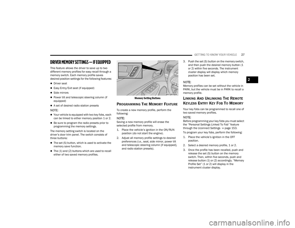
The memory setting switch is located on the
driver’s door trim panel. The switch consists of
three buttons:
The set (S) button, which is used to activate the
memory save function.
The (1) and (2) buttons which are used to recall
either of two saved memory profiles.
Memory Setting Buttons
PROGRAMMING THE MEMORY FEATURE
To create a new memory profile, perform the
following:
NOTE:Saving a new memory profile will erase the
selected profile from memory.
1. Place the vehicle’s ignition in the ON/RUN
position (do not start the engine).
2. Adjust all memory profile settings to desired preferences (i.e., seat, side mirror, power tilt
and telescopic steering column [if equipped],
and radio station presets). 3. Push the set (S) button on the memory switch,
and then push the desired memory button (1
or 2) within five seconds. The instrument
cluster display will display which memory
position has been set.
NOTE:Memory profiles can be set without the vehicle in
PARK, but the vehicle must be in PARK to recall a
memory profile.
LINKING AND UNLINKING THE REMOTE
K
EYLESS ENTRY KEY FOB TO MEMORY
Your key fobs can be programmed to recall one of
two saved memory profiles.
NOTE:Before programming your key fobs you must select
the “Personal Settings Linked To Fob” feature
through the Uconnect Settings Ú page 153.
To program your key fobs, perform the following:
1. Place the vehicle’s ignition in the OFF position.
2. Select a desired memory profile, 1 or 2.
3. Once the profile has been recalled, push and release the set (S) button on the memory
switch. Then, within five seconds, push and
release button (1) or (2) accordingly. “Memory
Profile Set” (1 or 2) will display in the
instrument cluster display.
2
23_WD_OM_EN_USC_t.book Page 27
Page 69 of 328
GETTING TO KNOW YOUR VEHICLE67
(Continued)
POWER INVERTER — IF EQUIPPED
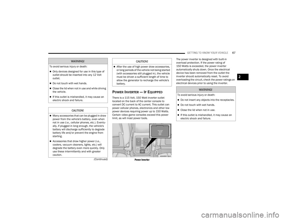
There is a 115 Volt, 150 Watt inverter outlet
located on the back of the center console to
convert DC current to AC current. This outlet can
power cellular phones, electronics and other low
power devices requiring power up to 150 Watts.
Certain video game consoles exceed this power
limit, as will most power tools.
Power Inverter
The power inverter is designed with built-in
overload protection. If the power rating of
150 Watts is exceeded, the power inverter
automatically shuts down. Once the electrical
device has been removed from the outlet the
inverter should automatically reset. To avoid
overloading the circuit, check the power ratings on
electrical devices prior to using the inverter.
WARNING!
To avoid serious injury or death:
Only devices designed for use in this type of
outlet should be inserted into any 12 Volt
outlet.
Do not touch with wet hands.
Close the lid when not in use and while driving
the vehicle.
If this outlet is mishandled, it may cause an
electric shock and failure.
CAUTION!
Many accessories that can be plugged in draw
power from the vehicle's battery, even when
not in use (i.e., cellular phones, etc.). Eventu
-
ally, if plugged in long enough, the vehicle's
battery will discharge sufficiently to degrade
battery life and/or prevent the engine from
starting.
Accessories that draw higher power (i.e.,
coolers, vacuum cleaners, lights, etc.) will
degrade the battery even more quickly. Only
use these intermittently and with greater
caution.
After the use of high power draw accessories,
or long periods of the vehicle not being started
(with accessories still plugged in), the vehicle
must be driven a sufficient length of time to
allow the generator to recharge the vehicle's
battery.
CAUTION!
WARNING!
To avoid serious injury or death:
Do not insert any objects into the receptacles.
Do not touch with wet hands.
Close the lid when not in use.
If this outlet is mishandled, it may cause an
electric shock and failure.
2
23_WD_OM_EN_USC_t.book Page 67
Page 71 of 328
GETTING TO KNOW YOUR VEHICLE69
Automatic Window Features
Auto-Down Feature
Both the driver and front passenger window
switches have an Auto-Down feature. Push the
window switch past the first detent, release, and
the window will go down automatically.
To cancel the Auto-Down movement, operate the
switch in either the up or down direction and
release the switch.
Auto-Up Feature With Anti-Pinch Protection —
Driver And Front Passenger Door Only
Lift the window switch fully upward to the second
detent, release, and the window will go up
automatically. To stop the window from going all the way up
during the Auto-Up operation, push down on the
switch briefly.
If the window runs into any obstacle during
Auto-Up, it will reverse direction and then go back
down. Remove the obstacle and use the window
switch again to close the window.
NOTE:Any impact due to rough road conditions may
trigger the auto reverse function unexpectedly
during Auto-Up. If this happens, pull the switch
lightly to the first detent and hold it to close the
window manually.
Reset Auto-Up
Should the Auto-Up feature stop working, the
window may need to be reset. To reset Auto-Up:
1. Make sure the door is fully closed.
2. Pull the window switch up to close the window
completely and continue to hold the switch up
for an additional two seconds after the window
is closed. 3. Push the window switch down firmly to the
second detent to open the window completely
and continue to hold the switch down for an
additional two seconds after the window is
fully open.
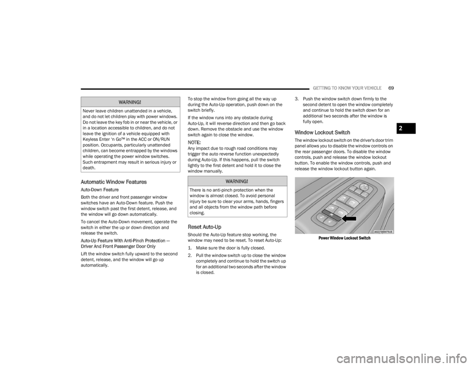
Window Lockout Switch
The window lockout switch on the driver's door trim
panel allows you to disable the window controls on
the rear passenger doors. To disable the window
controls, push and release the window lockout
button. To enable the window controls, push and
release the window lockout button again.
Power Window Lockout Switch
WARNING!
Never leave children unattended in a vehicle,
and do not let children play with power windows.
Do not leave the key fob in or near the vehicle, or
in a location accessible to children, and do not
leave the ignition of a vehicle equipped with
Keyless Enter ‘n Go™ in the ACC or ON/RUN
position. Occupants, particularly unattended
children, can become entrapped by the windows
while operating the power window switches.
Such entrapment may result in serious injury or
death.
WARNING!
There is no anti-pinch protection when the
window is almost closed. To avoid personal
injury be sure to clear your arms, hands, fingers
and all objects from the window path before
closing.
2
23_WD_OM_EN_USC_t.book Page 69
Page 74 of 328
72GETTING TO KNOW YOUR VEHICLE
NOTE:
Vehicle must be at a stop and the gear selector
must be in PARK.
While lifting the hood, use both hands.
Before lifting the hood, check that the wiper
arms are not in motion and not in the lifted posi -
tion.
CLOSING THE HOOD
In one continuous motion, pull down on the front
edge of the hood with moderate force until the
angle is below the crossover point (where the gas
props are no longer resisting) and let the hood
continue to fall closed from its own inertia.
LIFTGATE
POWER LIFTGATE — IF EQUIPPED
The power liftgate may be opened by
pushing the liftgate release handle
Ú page 22 or by pushing the liftgate
button on the key fob. Push the liftgate
button on the key fob twice within five seconds to
open or close the power liftgate.
NOTE:
When using the liftgate button on the key fob to
open the liftgate while the vehicle is locked, only
the liftgate will unlock leaving the other doors to
remain locked. Closing the liftgate will not relock
the liftgate. The lock button on the key fob, or
the Passive Entry lock button must be pushed to
relock.
If the electronic liftgate handle is used to open
the liftgate and all the doors unlock, the liftgate
and vehicle doors must be locked again. Use the
key fob, Passive Entry lock button, or the power
door lock switches on the front door panels.
The power liftgate may also be opened or closed by
pushing the liftgate button located on the front
overhead console. If the liftgate is fully open, it can
be closed by pushing the liftgate button located on
the left rear trim panel. If the liftgate is in motion,
pushing the button again will reverse the liftgate. When the liftgate button on the key fob is pushed
two times, the turn signals will flash to signal that
the liftgate is opening or closing (if Flash Lamps
with Lock is enabled in the Uconnect settings), and
the liftgate chime will be audible. The chime can be
turned on or off through the Uconnect Settings
Ú
page 153.
NOTE:
In the event of a power malfunction to the lift -
gate, an emergency liftgate latch release can be
used to open the liftgate. The emergency liftgate
latch release can be accessed through a snap-in
cover located on the liftgate trim panel.
If liftgate is left open for an extended period of
time, the liftgate may need to be closed manu -
ally to reset power liftgate functionality.
NOTE:
The power liftgate buttons will not operate if the
vehicle is in gear or the vehicle speed is above
0 mph (0 km/h).
WARNING!
Be sure the hood is fully latched before driving
your vehicle. If the hood is not fully latched, it
could open when the vehicle is in motion and
block your vision. Failure to follow this warning
could result in serious injury or death.WARNING!
During power operation, personal injury or cargo
damage may occur. Ensure the liftgate travel
path is clear. Make sure the liftgate is closed
and latched before driving away.
23_WD_OM_EN_USC_t.book Page 72
Page 82 of 328
80GETTING TO KNOW YOUR INSTRUMENT PANEL
LOCATION AND CONTROLS
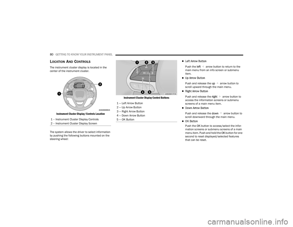
The instrument cluster display is located in the
center of the instrument cluster.
Instrument Cluster Display/Controls Location
The system allows the driver to select information
by pushing the following buttons mounted on the
steering wheel:
Instrument Cluster Display Control Buttons
Left Arrow Button
Push the left arrow button to return to the
main menu from an info screen or submenu
item.
Up Arrow Button
Push and release the up arrow button to
scroll upward through the main menu.
Right Arrow Button
Push and release the right arrow button to
access the information screens or submenu
screens of a main menu item.
Down Arrow Button
Push and release the down arrow button to
scroll downward through the main menu.
OK Button
Push the OK button to access/select the infor -
mation screens or submenu screens of a main
menu item. Push and hold the OK button for one
second to reset displayed/selected features
that can be reset.
1 – Instrument Cluster Display Controls
2 – Instrument Cluster Display Screen
1 — Left Arrow Button
2 — Up Arrow Button
3 — Right Arrow Button
4 — Down Arrow Button
5 — OK Button
23_WD_OM_EN_USC_t.book Page 80
Page 84 of 328
82GETTING TO KNOW YOUR INSTRUMENT PANEL
ENGINE OIL LIFE RESET
Use this QR code to access your
digital experience.
Oil Change Required
Your vehicle is equipped with an
engine oil change indicator
system. The “Oil Change
Required” message will display in
the instrument cluster display for five seconds
after a single chime has sounded, to indicate the
next scheduled oil change interval. The engine oil
change indicator system is duty cycle based, which
means the engine oil change interval may
fluctuate, dependent upon your personal driving
style.
Unless reset, this message will continue to display
each time the ignition is placed in the ON/RUN
position. To turn off the message temporarily, push
and release the OK or arrow buttons. To reset the
oil change indicator system (after performing the
scheduled maintenance), refer to the following
procedure. Vehicles Equipped With Keyless Enter ‘n Go™ —
Ignition
Use the steering wheel instrument cluster display
controls for the following procedure(s):
1. Without pressing the brake pedal, push the
ENGINE START/STOP button and place the
ignition in the ON/RUN position (do not start
the engine).
2. Push and release the down arrow button to
scroll downward through the main menu to
“Vehicle Info.”
3. Push and release the right arrow button to
access the ”Oil Life” screen.
4. Push and hold the OK button to reset oil life. If
conditions are met, the gauge and numeric
display will update to show 100%. If conditions
are not met a pop-up message of “To reset oil
life engine must be off with ignition in run” will
be displayed (for five seconds), and the user
will remain at the Oil Life screen.
5. Push and release the up or down arrow
button to exit the submenu screen.
NOTE:If the indicator message illuminates when you start
the vehicle, the oil change indicator system did not
reset. If necessary, repeat this procedure.
Secondary Method Of Resetting Engine Oil Life
1. Without pressing the brake pedal, push the ENGINE START/STOP button and place the
ignition to the ON/RUN position (do not start
the engine).
2. Fully press the accelerator pedal, slowly, three times within 10 seconds.
3. Without pushing the brake pedal, push the ENGINE START/STOP button once to return the
ignition to the OFF position.
NOTE:If the indicator message illuminates when you start
the vehicle, the oil change indicator system did not
reset. If necessary, repeat this procedure.
23_WD_OM_EN_USC_t.book Page 82
Page 85 of 328

GETTING TO KNOW YOUR INSTRUMENT PANEL83
DISPLAY AND MESSAGES
Includes the following, but not limited to:
The Reconfigurable Telltales section is divided into the white or yellow telltales area on the left, and the green or red telltales area on the right.Front Seat Belts Unbuckled
Driver Seat Belt UnbuckledPassenger Seat Belt Unbuckled
Traction Control Off Washer Fluid LowOil Pressure Low
Oil Change Due Fuel LowService Anti-lock Brake System
Service Electronic Throttle Control Service Power SteeringCruise Off
Cruise Ready ACC OverrideCruise Set To XXX mph or km/h
Service Shifter Tire Pressure Screen With Low Tire(s)Service Tire Pressure System
Park Brake Engaged Brake Fluid LowEngine Temperature Hot
Lights On Right Front Turn Signal Light OutRight Rear Turn Signal Light Out
Left Front Turn Signal Light Out Left Rear Turn Signal Light OutIgnition or Accessory On
Vehicle Not In Park Remote Start Active Push Start ButtonRemote Start Canceled Fuel Low
Remote Start Canceled Door Open Remote Start Canceled Hood OpenRemote Start Canceled Liftgate Open
Remote Start Canceled Time Expired Remote Start Disabled Start To ResetService Air Bag System
Service Air Bag Warning Light Door OpenLiftgate Open
Hood Open Shift Not AllowedVehicle Speed Too High To Shift to D
Vehicle Speed is Too High to Shift to R Vehicle Speed is Too High to Shift to PService Transmission
3
23_WD_OM_EN_USC_t.book Page 83
Page 86 of 328
84GETTING TO KNOW YOUR INSTRUMENT PANEL
INSTRUMENT CLUSTER DISPLAY MENU
I
TEMS
The instrument cluster display can be used to view
the main menu items for several features. Use the
up and down arrow buttons to scroll through
the driver interactive display menu options until
the desired menu is reached.
NOTE:Depending on the vehicle’s options, feature
settings may vary.
Main Gauge
Speedometer
Push and release the up or down arrow
button until the main gauge menu icon is displayed
in the instrument cluster display. Push and release
the left or right arrow button to select the
analog or digital type speedometer display. Push
and release the OK button to toggle units (mph or
km/h) of the speedometer.
Vehicle Info
Push and release the up or down arrow
button until the Vehicle Info icon/title is highlighted
in the instrument cluster display. Push the left
or right arrow button to scroll through the
information submenus. Tire Pressure Monitor System
If tire pressure is
OK for all tires a vehicle icon is
displayed with tire pressure values in each
corner of the icon.
If one or more tires have low pressure, “Inflate
Tire To XX” is displayed with the vehicle icon and
the tire pressure values in each corner of the
icon with the pressure value of the low tire are
displayed in a different color than the other tire
pressure value.
If the Tire Pressure system requires service,
“Service Tire Pressure System” is displayed.
Tire Pressure is an information only function, and
cannot be reset Ú page 188.
Transmission Temperature
Displays the actual transmission temperature.
Oil Temperature
Displays the actual oil temperature.
Oil Pressure
Displays the actual oil pressure.
Oil Life
Displays the current oil life of the vehicle.
Battery Voltage
Displays the current voltage level of the battery.
Performance Features — If Equipped
Push and release the up or down arrow
button until the Performance Features icon/title is
highlighted in the instrument cluster display. Push
and release the left or right arrow button to
scroll through the performance feature submenus.
The Performance Features include the following:
0-60 mph (0-100 km/h) Timer
Best
Last
Current
WARNING!
Measurement of vehicle statistics with the
Performance Features is intended for
off-highway or track use only and should not be
done on any public roadways. It is recommended
that these features be used in a controlled
environment and within the limits of the law. The
capabilities of the vehicle as measured by the
performance pages must never be exploited in a
reckless or dangerous manner, which can
jeopardize the user’s safety or the safety of
others. Only a safe, attentive, and skillful driver
can prevent accidents.
23_WD_OM_EN_USC_t.book Page 84