stop start DODGE DURANGO SRT 2018 Owner's Guide
[x] Cancel search | Manufacturer: DODGE, Model Year: 2018, Model line: DURANGO SRT, Model: DODGE DURANGO SRT 2018Pages: 568, PDF Size: 6.54 MB
Page 277 of 568
Operation
To activate AutoStick mode, move the gear selector into the
MANUAL (M) position (beside the DRIVE position), or tap
one of the shift paddles on the steering wheel. Tapping the
(-) shift paddle to enter AutoStick mode will downshift the
transmission to the next lower gear, while tapping (+) to
enter AutoStick mode will retain the current gear. The
current transmission gear will be displayed in the instru-
ment cluster. In AutoStick mode, you can use the gear
selector (in the MANUAL position), or the shift paddles, to
manually shift the transmission. Tapping the gear selector
forward (-) while in the MANUAL (M) position, or tapping
the (-) shift paddle on the steering wheel, will downshift
the transmission to the next lower gear. Tapping the
selector rearward (+) (or tapping the (+) shift paddle) will
command an upshift.
NOTE:The shift paddles may be disabled (or re-enabled,
as desired) using the SRT Drive Modes.
In AutoStick mode, the transmission will shift up or down
when (+/-) is manually selected by the driver (using the
gear selector or the shift paddles), unless an engine lugging
or overspeed condition would result. It will remain in the
selected gear until another upshift or downshift is chosen,
except as described below. •
The transmission will automatically downshift as the
vehicle slows (to prevent engine lugging) and will
display the current gear.
• The transmission will automatically downshift to first
gear when coming to a stop. After a stop, the driver
should manually upshift (+) the transmission as the
vehicle is accelerated.
• You can start out, from a stop, in first or second gear (or
third gear, in SNOW mode). Tapping (+) (at a stop) will
allow starting in second gear. Starting out in second or
third gear can be helpful in snowy or icy conditions.
• If a requested downshift would cause the engine to
over-speed, that shift will not occur.
• The system will ignore attempts to upshift at too low of
a vehicle speed.
• Holding the (-) paddle depressed, or holding the gear
selector in the (-) position, will downshift the transmis-
sion to the lowest gear possible at the current speed.
• Transmission shifting will be more noticeable when
AutoStick is enabled.
• The system may revert to automatic shift mode if a fault
or overheat condition is detected.
6
STARTING AND OPERATING 275
Page 280 of 568
Launch control will abort before launch completion, dis-
play “Launch Aborted” in the cluster under any the
following conditions:
•The accelerator pedal is released during launch. ESC
system continues in ESC Full ON.
• The ESC system detects that the vehicle is no longer
moving in a straight line.
• The “ESC OFF” button is pushed to change the system
to another mode.
NOTE: After launch control has been aborted, ESC will
return to its current ESC mode.
CAUTION!
Do not attempt to shift when the drive wheels are
spinning and do not have traction. Damage to the
transmission may occur.
Guidelines For Track Use
NOTE: Because of the extreme conditions encountered
during track use, any damage or wear associated with
track use may not be covered by warranty.
• If your SRT vehicle is equipped with Drive Modes, they
will alter the vehicle’s performance in various driving
situations. It is recommended that your vehicle operates
in SPORT or TRACK modes during the track event.
• Prior to each track event/day, verify all fluids are at the
correct levels. Refer to “Fluid Capacities” in “Technical
Specifications” for further information.
• Prior to each track event, verify the front and rear brake
pads have more than ½ pad thickness remaining. If the
brake pads require changing, please burnish prior to
track outing at full pace.
NOTE: Use of DOT 4 brake fluid is suggested for extended
track usage due to increased thermal capacity.
• At the conclusion of each track event, it is recommended
that a brake bleed procedure is performed to maintain
the pedal feel and stopping capability of your Brembo
High Performance brake system.
278 STARTING AND OPERATING
Page 288 of 568
You can change the mode by using the Cruise Control
buttons. The two control modes function differently. Al-
ways confirm which mode is selected.
WARNING!
•Adaptive Cruise Control (ACC) is a convenience
system. It is not a substitute for active driving
involvement. It is always the driver ’s responsibility
to be attentive of road, traffic, and weather condi-
tions, vehicle speed, distance to the vehicle ahead;
and, most importantly, brake operation to ensure safe
operation of the vehicle under all road conditions.
Your complete attention is always required while
driving to maintain safe control of your vehicle.
Failure to follow these warnings can result in a
collision and death or serious personal injury.
• The ACC system:
• Does not react to pedestrians, oncoming vehicles,
and stationary objects (e.g., a stopped vehicle in a
traffic jam or a disabled vehicle).
• Cannot take street, traffic, and weather conditions
into account, and may be limited upon adverse
sight distance conditions.
(Continued)
WARNING! (Continued)
•Does not always fully recognize complex driving
conditions, which can result in wrong or missing
distance warnings.
• Will bring the vehicle to a complete stop while
following a target vehicle and hold the vehicle for
2 seconds in the stop position. If the target vehicle
does not start moving within two seconds the ACC
system will display a message that the system will
release the brakes and that the brakes must be
applied manually. An audible chime will sound
when the brakes are released.
You should switch off the ACC system:
• When driving in fog, heavy rain, heavy snow, sleet,
heavy traffic, and complex driving situations (i.e., in
highway construction zones).
• When entering a turn lane or highway off ramp;
when driving on roads that are winding, icy, snow-
covered, slippery, or have steep uphill or downhill
slopes.
• When towing a trailer up or down steep slopes.
• When circumstances do not allow safe driving at a
constant speed.
286 STARTING AND OPERATING
Page 293 of 568
•If the button is continually pushed, the set speed will
continue to increase in 10 km/h increments until the
button is released. The increase in set speed is reflected
in the instrument cluster display.
To Decrease Speed
While ACC is set, the set speed can be decreased by
pushing the SET (-)button.
The driver’s preferred units can be selected through the
instrument panel settings. Refer to “Getting To Know Your
Instrument Panel” for more information. The speed decre-
ment shown is dependant on the chosen speed unit of U.S.
(mph) or Metric (km/h):
U.S. Speed (mph)
• Pushing the SET (-)button once will result in a 1 mph
decrease in set speed. Each subsequent tap of the button
results in a decrease of 1 mph.
• If the button is continually pushed, the set speed will
continue to decrease in 5 mph decrements until the
button is released. The decrease in set speed is reflected
in the instrument cluster display. Metric Speed (km/h)
•
Pushing the SET (-)button once will result in a 1 km/h
decrease in set speed. Each subsequent tap of the button
results in a decrease of 1 km/h.
• If the button is continually pushed, the set speed will
continue to decrease in 10 km/h decrements until the
button is released. The decrease in set speed is reflected
in the instrument cluster display.
NOTE:
• When you override and push the SET (+)button or SET
(-) buttons, the new set speed will be the current speed
of the vehicle.
• When you use the SET (-)button to decelerate, if the
engine’s braking power does not slow the vehicle suffi-
ciently to reach the set speed, the brake system will
automatically slow the vehicle.
• The ACC system applies the brake down to a full stop
when following a target vehicle. If an ACC host vehicle
follows a target vehicle to a standstill, the host vehicle
will release the vehicle brakes two seconds after coming
to a full stop.
6
STARTING AND OPERATING 291
Page 297 of 568
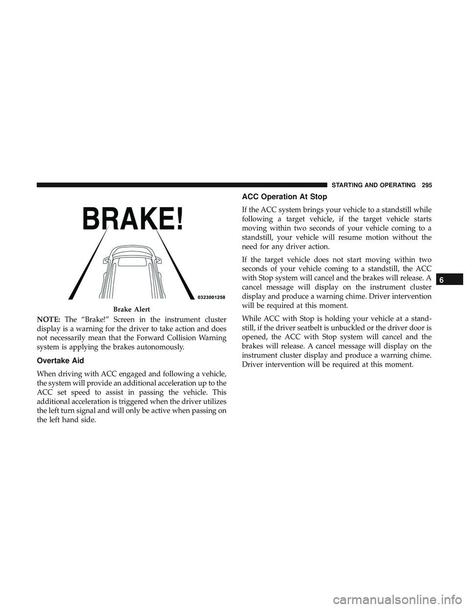
NOTE:The “Brake!” Screen in the instrument cluster
display is a warning for the driver to take action and does
not necessarily mean that the Forward Collision Warning
system is applying the brakes autonomously.
Overtake Aid
When driving with ACC engaged and following a vehicle,
the system will provide an additional acceleration up to the
ACC set speed to assist in passing the vehicle. This
additional acceleration is triggered when the driver utilizes
the left turn signal and will only be active when passing on
the left hand side.
ACC Operation At Stop
If the ACC system brings your vehicle to a standstill while
following a target vehicle, if the target vehicle starts
moving within two seconds of your vehicle coming to a
standstill, your vehicle will resume motion without the
need for any driver action.
If the target vehicle does not start moving within two
seconds of your vehicle coming to a standstill, the ACC
with Stop system will cancel and the brakes will release. A
cancel message will display on the instrument cluster
display and produce a warning chime. Driver intervention
will be required at this moment.
While ACC with Stop is holding your vehicle at a stand-
still, if the driver seatbelt is unbuckled or the driver door is
opened, the ACC with Stop system will cancel and the
brakes will release. A cancel message will display on the
instrument cluster display and produce a warning chime.
Driver intervention will be required at this moment.
Brake Alert
6
STARTING AND OPERATING 295
Page 304 of 568
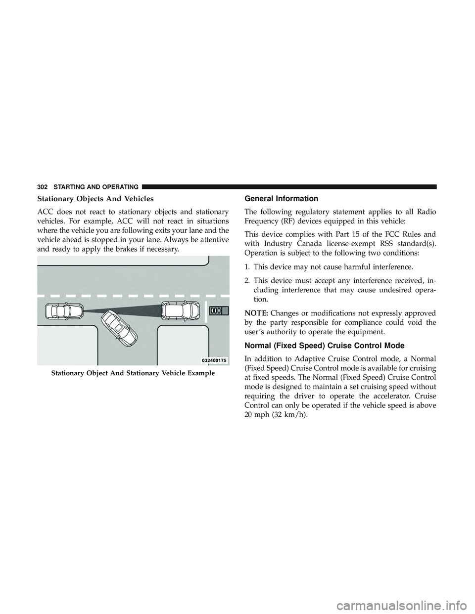
Stationary Objects And Vehicles
ACC does not react to stationary objects and stationary
vehicles. For example, ACC will not react in situations
where the vehicle you are following exits your lane and the
vehicle ahead is stopped in your lane. Always be attentive
and ready to apply the brakes if necessary.
General Information
The following regulatory statement applies to all Radio
Frequency (RF) devices equipped in this vehicle:
This device complies with Part 15 of the FCC Rules and
with Industry Canada license-exempt RSS standard(s).
Operation is subject to the following two conditions:
1. This device may not cause harmful interference.
2. This device must accept any interference received, in-cluding interference that may cause undesired opera-
tion.
NOTE: Changes or modifications not expressly approved
by the party responsible for compliance could void the
user ’s authority to operate the equipment.
Normal (Fixed Speed) Cruise Control Mode
In addition to Adaptive Cruise Control mode, a Normal
(Fixed Speed) Cruise Control mode is available for cruising
at fixed speeds. The Normal (Fixed Speed) Cruise Control
mode is designed to maintain a set cruising speed without
requiring the driver to operate the accelerator. Cruise
Control can only be operated if the vehicle speed is above
20 mph (32 km/h).
Stationary Object And Stationary Vehicle Example
302 STARTING AND OPERATING
Page 316 of 568
WARNING!(Continued)
your surroundings. Failure to do so can result in
serious injury or death.
• Before using ParkSense, it is strongly recommended
that the ball mount and hitch ball assembly is
disconnected from the vehicle when the vehicle is
not used for towing. Failure to do so can result in
injury or damage to vehicles or obstacles because the
hitch ball will be much closer to the obstacle than the
rear fascia when the loudspeaker sounds the con-
tinuous tone. Also, the sensors could detect the ball
mount and hitch ball assembly, depending on its size
and shape, giving a false indication that an obstacle
is behind the vehicle.
CAUTION!
•ParkSense is only a parking aid and it is unable to
recognize every obstacle, including small obstacles.
Parking curbs might be temporarily detected or not
detected at all. Obstacles located above or below the
sensors will not be detected when they are in close
proximity.
(Continued)
CAUTION! (Continued)
•The vehicle must be driven slowly when using
ParkSense in order to be able to stop in time when an
obstacle is detected. It is recommended that the
driver looks over his/her shoulder when using
ParkSense.
PARKSENSE FRONT AND REAR PARK ASSIST —
IF EQUIPPED
The ParkSense Park Assist system provides visual and
audible indications of the distance between the rear and/or
front fascia and a detected obstacle when backing up or
moving forward, e.g. during a parking maneuver. If your
vehicle is equipped with an automatic transmission, the
vehicle brakes may be automatically applied and released
when performing a reverse parking maneuver if the sys-
tem detects a possible collision with an obstacle.
314 STARTING AND OPERATING
Page 327 of 568
WARNING!(Continued)
•Before using ParkSense, it is strongly recommended
that the ball mount and hitch ball assembly is
disconnected from the vehicle when the vehicle is
not used for towing. Failure to do so can result in
injury or damage to vehicles or obstacles because the
hitch ball will be much closer to the obstacle than the
rear fascia when the loudspeaker sounds the con-
tinuous tone. Also, the sensors could detect the ball
mount and hitch ball assembly, depending on its size
and shape, giving a false indication that an obstacle
is behind the vehicle.
CAUTION!
•ParkSense is only a parking aid and it is unable to
recognize every obstacle, including small obstacles. Park-
ing curbs might be temporarily detected or not detected
at all. Obstacles located above or below the sensors will
not be detected when they are in close proximity.
•The vehicle must be driven slowly when using
ParkSense in order to be able to stop in time when an
obstacle is detected. It is recommended that the driver
looks over his/her shoulder when using ParkSense.
LANESENSE — IF EQUIPPED
LaneSense Operation
The LaneSense system is operational at speeds above
37 mph (60 km/h) and below 112 mph (180 km/h). The
LaneSense system uses a forward looking camera to detect
lane markings and measure vehicle position within the
lane boundaries.
When both lane markings are detected and the driver
unintentionally drifts out of the lane (no turn signal
applied), the LaneSense system provides a haptic warning
in the form of torque applied to the steering wheel to
prompt the driver to remain within the lane boundaries. If
the driver continues to unintentionally drift out of the lane,
the LaneSense system provides a visual warning through
the instrument cluster display to prompt the driver to
remain within the lane boundaries.
The driver may manually override the haptic warning by
applying torque into the steering wheel at any time.
6
STARTING AND OPERATING 325
Page 333 of 568
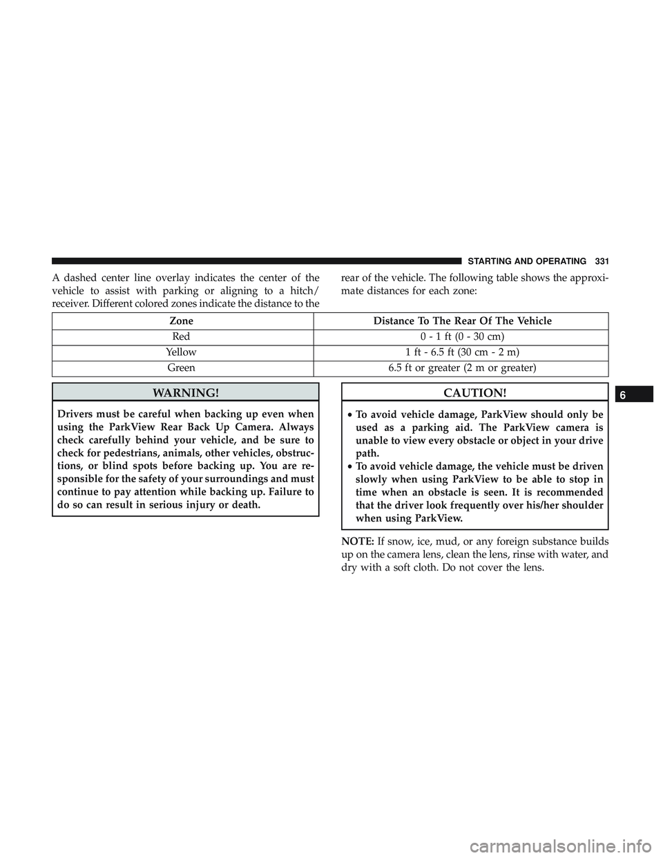
A dashed center line overlay indicates the center of the
vehicle to assist with parking or aligning to a hitch/
receiver. Different colored zones indicate the distance to therear of the vehicle. The following table shows the approxi-
mate distances for each zone:
Zone
Distance To The Rear Of The Vehicle
Red 0 - 1 ft (0 - 30 cm)
Yellow 1 ft - 6.5 ft (30 cm - 2 m)
Green 6.5 ft or greater (2 m or greater)
WARNING!
Drivers must be careful when backing up even when
using the ParkView Rear Back Up Camera. Always
check carefully behind your vehicle, and be sure to
check for pedestrians, animals, other vehicles, obstruc-
tions, or blind spots before backing up. You are re-
sponsible for the safety of your surroundings and must
continue to pay attention while backing up. Failure to
do so can result in serious injury or death.
CAUTION!
•To avoid vehicle damage, ParkView should only be
used as a parking aid. The ParkView camera is
unable to view every obstacle or object in your drive
path.
• To avoid vehicle damage, the vehicle must be driven
slowly when using ParkView to be able to stop in
time when an obstacle is seen. It is recommended
that the driver look frequently over his/her shoulder
when using ParkView.
NOTE: If snow, ice, mud, or any foreign substance builds
up on the camera lens, clean the lens, rinse with water, and
dry with a soft cloth. Do not cover the lens.
6
STARTING AND OPERATING 331
Page 346 of 568
WARNING!
•Do not connect trailer brakes to your vehicle’s hy-
draulic brake lines. It can overload your brake sys-
tem and cause it to fail. You might not have brakes
when you need them and could have an accident.
• Towing any trailer will increase your stopping dis-
tance. When towing, you should allow for additional
space between your vehicle and the vehicle in front
of you. Failure to do so could result in an accident.
CAUTION!
If the trailer weighs more than 1,000 lbs (453 kg)
loaded, it should have its own brakes and they should
be of adequate capacity. Failure to do this could lead to
accelerated brake lining wear, higher brake pedal
effort, and longer stopping distances.
Towing Requirements — Trailer Lights And Wiring
Whenever you pull a trailer, regardless of the trailer size,
stoplights and turn signals on the trailer are required for
motoring safety.
The Trailer Tow Package may include a four- and seven-pin
wiring harness. Use a factory approved trailer harness and
connector.
NOTE: Do not cut or splice wiring into the vehicle’s wiring
harness.
The electrical connections are all complete to the vehicle
but you must mate the harness to a trailer connector. Refer
to the following illustrations.
NOTE:
• Disconnect trailer wiring connector from the vehicle
before launching a boat (or any other device plugged
into vehicle’s electrical connect) into water.
• Be sure to reconnect after clear from water area.
344 STARTING AND OPERATING