air condition DODGE DURANGO SRT 2018 Owners Manual
[x] Cancel search | Manufacturer: DODGE, Model Year: 2018, Model line: DURANGO SRT, Model: DODGE DURANGO SRT 2018Pages: 568, PDF Size: 6.54 MB
Page 51 of 568
•Push the switcha second time to turn the LO
setting on.
• Push the switcha third time to turn the heating
elements off.
When the HI-level setting is selected, the heater will
provide a boosted heat level during the first four minutes
of operation. Then, the heat output will drop to the normal
HI-level. If the HI-level setting is selected, the system will
automatically switch to LO-level after approximately 60
minutes of continuous operation. At that time, the number
of indicator lights changes from two to one, indicating the
change. The LO-level setting will turn off automatically
after approximately 45 minutes.
WARNING!
• Persons who are unable to feel pain to the skin
because of advanced age, chronic illness, diabetes,
spinal cord injury, medication, alcohol use, exhaus-
tion or other physical condition must exercise care
when using the seat heater. It may cause burns even
at low temperatures, especially if used for long
periods of time.
(Continued)
WARNING! (Continued)
•Do not place anything on the seat or seatback that
insulates against heat, such as a blanket or cushion.
This may cause the seat heater to overheat. Sitting in
a seat that has been overheated could cause serious
burns due to the increased surface temperature of the
seat.
Front Ventilated Seats — If Equipped
Located in the seat cushion and seat back are fans that
draw the air from the passenger compartment and move
air through fine perforations in the seat cover to help keep
the driver and front passenger cooler in higher ambient
temperatures. The fans operate at two speeds, HI and LO.
The front ventilated seats control buttons are located
within the Uconnect system. You can gain access to the
control buttons through the climate screen or the controls
screen.
• Press the ventilated seat button
once to choose HI.
•Press the ventilated seat buttona second time to
choose LO.
• Press the ventilated seat buttona third time to turn
the ventilated seat off. 3
GETTING TO KNOW YOUR VEHICLE 49
Page 85 of 568
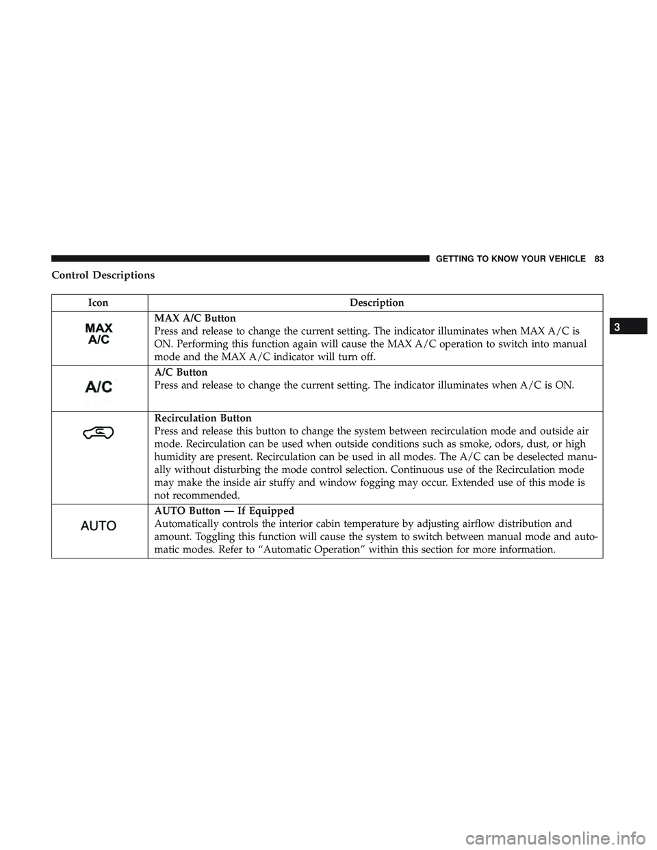
Control Descriptions
IconDescription
MAX A/C Button
Press and release to change the current setting. The indicator illuminates when MAX A/C is
ON. Performing this function again will cause the MAX A/C operation to switch into manual
mode and the MAX A/C indicator will turn off.
A/C Button
Press and release to change the current setting. The indicator illuminates when A/C is ON.
Recirculation Button
Press and release this button to change the system between recirculation mode and outside air
mode. Recirculation can be used when outside conditions such as smoke, odors, dust, or high
humidity are present. Recirculation can be used in all modes. The A/C can be deselected manu-
ally without disturbing the mode control selection. Continuous use of the Recirculation mode
may make the inside air stuffy and window fogging may occur. Extended use of this mode is
not recommended.
AUTO Button — If Equipped
Automatically controls the interior cabin temperature by adjusting airflow distribution and
amount. Toggling this function will cause the system to switch between manual mode and auto-
matic modes. Refer to “Automatic Operation” within this section for more information.
3
GETTING TO KNOW YOUR VEHICLE 83
Page 88 of 568
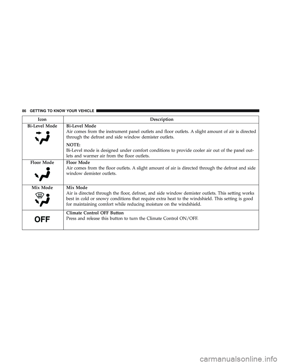
IconDescription
Bi-Level Mode
Bi-Level Mode
Air comes from the instrument panel outlets and floor outlets. A slight amount of air is directed
through the defrost and side window demister outlets.
NOTE:
Bi-Level mode is designed under comfort conditions to provide cooler air out of the panel out-
lets and warmer air from the floor outlets.
Floor Mode
Floor Mode
Air comes from the floor outlets. A slight amount of air is directed through the defrost and side
window demister outlets.
Mix Mode
Mix Mode
Air is directed through the floor, defrost, and side window demister outlets. This setting works
best in cold or snowy conditions that require extra heat to the windshield. This setting is good
for maintaining comfort while reducing moisture on the windshield.
Climate Control OFF Button
Press and release this button to turn the Climate Control ON/OFF.
86 GETTING TO KNOW YOUR VEHICLE
Page 95 of 568
Climate Control Functions
A/C (Air Conditioning)
The Air Conditioning (A/C) button allows the operator to
manually activate or deactivate the air conditioning sys-
tem. When the air conditioning system is turned on, cool
dehumidified air will flow through the outlets into the
cabin. For improved fuel economy, press the A/C button to
turn off the air conditioning and manually adjust the
blower and airflow mode settings. Also, make sure to select
only Panel, Bi-Level, or Floor modes.
NOTE:
•For Manual Climate Controls, if the system is in Mix,
Floor or Defrost Mode, the A/C can be turned off, but
the A/C system shall remain active to prevent fogging of
the windows.
• If fog or mist appears on the windshield or side glass,
select Defrost mode and adjust blower speed if needed.
• If your air conditioning performance seems lower than
expected, check the front of the A/C condenser (located
in front of the radiator), for an accumulation of dirt or
insects. Clean with a gentle water spray from the front of
the radiator and through the condenser. MAX A/C
MAX A/C sets the control for maximum cooling perfor-
mance.
Press and release to toggle between MAX A/C and the
prior settings. The button illuminates when MAX A/C is
on.
In MAX A/C, the blower level and mode position can be
adjusted to desired user settings. Pressing other settings
will cause the MAX A/C operation to switch to the selected
setting and MAX A/C to exit.
Recirculation
When outside air contains smoke, odors, or high humidity,
or if rapid cooling is desired, you may wish to recirculate
interior air by pressing the recirculation control button. The
recirculation indicator will illuminate when this button is
selected. Press the button a second time to turn off the
recirculation mode and allow outside air into the vehicle.
NOTE:
In cold weather, use of recirculation mode may lead
to excessive window fogging. The recirculation feature
may be unavailable (button on the touchscreen greyed out)
if conditions exist that could create fogging on the inside of
the windshield.
3
GETTING TO KNOW YOUR VEHICLE 93
Page 97 of 568
CAUTION!
Interior air enters the Rear Automatic Temperature
Control System through an intake grille, located in the
right side trim panel behind the third row seats. The
heater outlets are located in the right side trim panel,
just behind the sliding door. Do not block or place
objects directly in front of the inlet grille or heater
outlets. The electrical system could overload causing
damage to the blower motor.
Rear Temperature Control
To change the temperature in the rear of the vehicle, push
the temperature buttons. The rear temperature settings are
displayed in the rear ATC panel.
When rear controls are locked by the front system, the Rear
Temperature Lock symbol on the ATC panel is illuminated
and any rear overhead adjustments are ignored.
When the Sync feature is active, the rear temperature is
synchronized to the driver ’s temperature setting. If the rear
temperature is changed, the Sync feature will deactivate.
Operating Tips
NOTE:Refer to the chart at the end of this section for
suggested control settings for various weather conditions.
Summer Operation
The engine cooling system must be protected with a
high-quality antifreeze coolant to provide proper corrosion
protection and to protect against engine overheating. A
solution of 50% OAT (Organic Additive Technology) cool-
ant that meets the requirements of FCA Material Standard
MS.90032 and 50% water is recommended. Refer to “Fluids
and Lubricants” in “Technical Specifications” for proper
coolant selection.
Winter Operation
Use of the Air Recirculation mode during winter months is
not recommended because it may cause window fogging.
Vacation/Storage
Before you store your vehicle, or keep it out of service (i.e.,
vacation) for two weeks or more, run the air conditioning
system at idle for about five minutes, in fresh air with the
blower setting on high. This will ensure adequate system
lubrication to minimize the possibility of compressor dam-
age when the system is started again.
3
GETTING TO KNOW YOUR VEHICLE 95
Page 139 of 568
3. Temperature Gauge•The temperature gauge shows engine coolant tem-
perature. Any reading within the normal range indi-
cates that the engine cooling system is operating
satisfactorily.
• The gauge pointer will likely indicate a higher tem-
perature when driving in hot weather, up mountain
grades, or when towing a trailer. It should not be
allowed to exceed the upper limits of the normal
operating range.
WARNING!
A hot engine cooling system is dangerous. You or
others could be badly burned by steam or boiling
coolant. You may want to call an authorized dealer for
service if your vehicle overheats. If you decide to look
under the hood yourself, see “Maintaining Your Ve-
hicle”. Follow the warnings under the Cooling System
Pressure Cap paragraph.
CAUTION!
Driving with a hot engine cooling system could dam-
age your vehicle. If the temperature gauge reads “H”
pull over and stop the vehicle. Idle the vehicle with the
air conditioner turned off until the pointer drops back
into the normal range. If the pointer remains on the
“H”, turn the engine off immediately and call an
authorized dealer for service.
4. Fuel Gauge •The pointer shows the level of fuel in the fuel tank
when the Keyless Push Button Ignition is in the
ON/RUN position.
•
The fuel pump symbol points to the side of the
vehicle where the fuel door is located.
5. Instrument Cluster Display
•The instrument cluster display features a driver-
interactive display. Refer to “Instrument Cluster Dis-
play” in “Getting To Know Your Instrument Panel” for
further information.
NOTE: The hard telltales will illuminate for a bulb check
when the ignition is first cycled.
4
GETTING TO KNOW YOUR INSTRUMENT PANEL 137
Page 154 of 568
If the light remains on when the parking brake has been
disengaged, and the fluid level is at the full mark on the
master cylinder reservoir, it indicates a possible brake
hydraulic system malfunction or that a problem with the
Brake Booster has been detected by the Anti-Lock Brake
System (ABS) / Electronic Stability Control (ESC) system.
In this case, the light will remain on until the condition has
been corrected. If the problem is related to the brake
booster, the ABS pump will run when applying the brake,
and a brake pedal pulsation may be felt during each stop.
The dual brake system provides a reserve braking capacity
in the event of a failure to a portion of the hydraulic
system. A leak in either half of the dual brake system is
indicated by the Brake Warning Light, which will turn on
when the brake fluid level in the master cylinder has
dropped below a specified level.
The light will remain on until the cause is corrected.
NOTE:The light may flash momentarily during sharp
cornering maneuvers, which change fluid level conditions.
The vehicle should have service performed, and the brake
fluid level checked.
If brake failure is indicated, immediate repair is necessary.WARNING!
Driving a vehicle with the red brake light on is
dangerous. Part of the brake system may have failed. It
will take longer to stop the vehicle. You could have a
collision. Have the vehicle checked immediately.
Vehicles equipped with the Anti-Lock Brake System (ABS)
are also equipped with Electronic Brake Force Distribution
(EBD). In the event of an EBD failure, the Brake Warning
Light will turn on along with the ABS Light. Immediate
repair to the ABS system is required.
Operation of the Brake Warning Light can be checked by
turning the ignition switch from the OFF position to the
ON/RUN position. The light should illuminate for ap-
proximately two seconds. The light should then turn off
unless the parking brake is applied or a brake fault is
detected. If the light does not illuminate, have the light
inspected by an authorized dealer.
The light also will turn on when the parking brake is
applied with the ignition switch in the ON/RUN position.
NOTE: This light shows only that the parking brake is
applied. It does not show the degree of brake application.
152 GETTING TO KNOW YOUR INSTRUMENT PANEL
Page 159 of 568
— Electronic Stability Control (ESC) Off Warning
Light — If Equipped
This warning light indicates the Electronic Stability Control
(ESC) is off.
Each time the ignition is turned to ON/RUN or ACC/ON/
RUN, the ESC system will be on, even if it was turned off
previously.
The ESC OFF indicator will be lit any time the Traction
Mode is set to Sport, Track or Full OFF in Drive Modes.
— Low Washer Fluid Warning Light — If
Equipped
This warning light will illuminate when the windshield
washer fluid is low.
— Tire Pressure Monitoring System (TPMS)
Warning Light
The warning light switches on and a message is displayed
to indicate that the tire pressure is lower than the recom-
mended value and/or that slow pressure loss is occurring.
In these cases, optimal tire duration and fuel consumption
may not be guaranteed. Should one or more tires be in the condition mentioned
above, the display will show the indications corresponding
to each tire.
CAUTION!
Do not continue driving with one or more flat tires as
handling may be compromised. Stop the vehicle,
avoiding sharp braking and steering. If a tire puncture
occurs, repair immediately using the dedicated tire
repair kit and contact your authorized dealer as soon as
possible.
Each tire, including the spare (if provided), should be
checked monthly when cold and inflated to the inflation
pressure recommended by the vehicle manufacturer on the
vehicle placard or tire inflation pressure label. (If your
vehicle has tires of a different size than the size indicated
on the vehicle placard or tire inflation pressure label, you
should determine the proper tire inflation pressure for
those tires.)4
GETTING TO KNOW YOUR INSTRUMENT PANEL 157
Page 171 of 568
WARNING!(Continued)
•The capabilities of an ABS equipped vehicle must never
be exploited in a reckless or dangerous manner that
could jeopardize the user ’s safety or the safety of others.
ABS is designed to function with the OEM tires. Modifica-
tion may result in degraded ABS performance.
Anti-Lock Brake Warning Light
The yellow “Anti-Lock Brake Warning Light” will turn on
when the ignition is turned to the ON/RUN mode and
may stay on for as long as four seconds.
If the “Anti-Lock Brake Warning Light” remains on or
comes on while driving, it indicates that the anti-lock
portion of the brake system is not functioning and that
service is required. However, the conventional brake sys-
tem will continue to operate normally if the “Anti-Lock
Brake Warning Light” is on.
If the “Anti-Lock Brake Warning Light” is on, the brake
system should be serviced as soon as possible to restore the
benefits of anti-lock brakes. If the “Anti-Lock Brake Warn-
ing Light” does not come on when the ignition is turned to
the ON/RUN mode, have the light repaired as soon as
possible.
Electronic Brake Control System
Your vehicle is equipped with an advanced Electronic
Brake Control system (EBC). This system includes Elec-
tronic Brake Force Distribution (EBD), Anti-Lock Brake
System (ABS), Brake Assist System (BAS), Hill Start Assist
(HSA), Traction Control System (TCS), Electronic Stability
Control (ESC), and Electronic Roll Mitigation (ERM). These
systems work together to enhance both vehicle stability
and control in various driving conditions.
Your vehicle may also be equipped with Trailer Sway
Control (TSC), Ready Alert Braking (RAB), Rain Brake
Support (RBS), and Dynamic Steering Torque (DST).
Electronic Brake Force Distribution (EBD)
This function manages the distribution of the braking
torque between the front and rear axles by limiting braking
pressure to the rear axle. This is done to prevent overslip of
the rear wheels to avoid vehicle instability, and to prevent
the rear axle from entering ABS before the front axle.
Brake System Warning Light
The red “Brake System Warning Light” will turn on when
the ignition is turned to the ON/RUN mode and may stay
on for as long as four seconds.
5
SAFETY 169
Page 172 of 568
If the “Brake System Warning Light” remains on or comes
on while driving, it indicates that the brake system is not
functioning properly and that immediate service is re-
quired. If the “Brake System Warning Light” does not come
on when the ignition is turned to the ON/RUN mode, have
the light repaired as soon as possible.
Brake Assist System (BAS)
The BAS is designed to optimize the vehicle’s braking
capability during emergency braking maneuvers. The sys-
tem detects an emergency braking situation by sensing the
rate and amount of brake application and then applies
optimum pressure to the brakes. This can help reduce
braking distances. The BAS complements the anti-lock
brake system (ABS). Applying the brakes very quickly
results in the best BAS assistance. To receive the benefit of
the system, you must apply continuous braking pressure
during the stopping sequence, (do not “pump” the brakes).
Do not reduce brake pedal pressure unless braking is no
longer desired. Once the brake pedal is released, the BAS is
deactivated.
WARNING!
The Brake Assist System (BAS) cannot prevent the
natural laws of physics from acting on the vehicle, nor
can it increase the traction afforded by prevailing road
conditions. BAS cannot prevent collisions, including
those resulting from excessive speed in turns, driving
on very slippery surfaces, or hydroplaning. The capa-
bilities of a BAS-equipped vehicle must never be
exploited in a reckless or dangerous manner, which
could jeopardize the user’s safety or the safety of
others.
Hill Start Assist (HSA)
The HSA system is designed to mitigate roll back from a
complete stop while on an incline. If the driver releases the
brake while stopped on an incline, HSA will continue to
hold the brake pressure for a short period. If the driver
does not apply the throttle before this time expires, the
system will release brake pressure and the vehicle will roll
down the hill as normal.
170 SAFETY