start stop button DODGE DURANGO SRT 2019 User Guide
[x] Cancel search | Manufacturer: DODGE, Model Year: 2019, Model line: DURANGO SRT, Model: DODGE DURANGO SRT 2019Pages: 572, PDF Size: 6.59 MB
Page 271 of 572
Fuel Economy (ECO) Mode
The Fuel Economy (ECO) mode can improve the vehicle’s
overall fuel economy during normal driving conditions.
ECO mode can be enabled or disabled through your
Uconnect system.
When the Fuel Economy (ECO) Mode is enabled, the
vehicle control systems will change the following:
•The transmission will upshift sooner and downshift
later.
• In SRT models, the transmission will launch (from a
stop) in 2nd gear.
• The overall driving performance will be more conserva-
tive.
• Some ECO mode functions may be temporarily inhib-
ited based on temperature and other factors.
Eight-Speed Automatic Transmission
The transmission gear range (PRNDM) is displayed both
on the gear selector and in the instrument cluster. To select
a gear range, press the lock button on the gear selector and
move the selector rearward or forward. To shift the trans-
mission out of PARK, the engine must be running and the
brake pedal must be pressed. You must also press the brake pedal to shift from NEUTRAL into DRIVE or REVERSE
when the vehicle is stopped or moving at low speeds (refer
to “Brake/Transmission Shift Interlock System” in this
section). Select the DRIVE range for normal driving.
NOTE:
In the event of a mismatch between the gear
selector position and the actual transmission gear (for
example, driver selects PARK while driving), the position
indicator will blink continuously until the selector is re-
turned to the proper position, or the requested shift can be
completed.
The electronically-controlled transmission adapts its shift
schedule based on driver inputs, along with environmental
and road conditions. The transmission electronics are self-
calibrating; therefore, the first few shifts on a new vehicle
may be somewhat abrupt. This is a normal condition, and
precision shifts will develop within a few hundred miles
(kilometers).
Only shift from DRIVE to PARK or REVERSE when the
accelerator pedal is released and the vehicle is stopped. Be
sure to keep your foot on the brake pedal when shifting
between these gears.
The transmission gear selector provides PARK, REVERSE,
NEUTRAL, DRIVE and MANUAL (AutoStick) shift posi-
tions. Manual shifts can be made using the AutoStick shift
6
STARTING AND OPERATING 269
Page 274 of 572
WARNING!(Continued)
engine is idling normally and your foot is firmly
pressing the brake pedal.
• Unintended movement of a vehicle could injure
those in or near the vehicle. As with all vehicles, you
should never exit a vehicle while the engine is
running. Before exiting a vehicle, always come to a
complete stop, then apply the parking brake, shift
the transmission into PARK, and turn the ignition
OFF. When the ignition is in the OFF mode, the
transmission is locked in PARK, securing the vehicle
against unwanted movement.
• When exiting the vehicle, always make sure the
ignition is in the OFF mode, remove the key fob from
the vehicle, and lock the vehicle.
• Never leave children alone in a vehicle, or with
access to an unlocked vehicle. Allowing children to
be in a vehicle unattended is dangerous for a number
of reasons. A child or others could be seriously or
fatally injured. Children should be warned not to
touch the parking brake, brake pedal or the trans-
mission gear selector.
(Continued)
WARNING! (Continued)
•Do not leave the key fob in or near the vehicle (or in
a location accessible to children), and do not leave
the ignition in the ACC or ON/RUN mode. A child
could operate power windows, other controls, or
move the vehicle.
CAUTION!
• Before moving the transmission gear selector out of
PARK, you must start the engine, and also press the
brake pedal. Otherwise, damage to the gear selector
could result.
• DO NOT race the engine when shifting from PARK
or NEUTRAL into another gear range, as this can
damage the drivetrain.
The following indicators should be used to ensure that you
have properly engaged the transmission into the PARK
position:
• When shifting into PARK, push the lock button on the
gear selector and firmly move the selector all the way
forward until it stops and is fully seated.
272 STARTING AND OPERATING
Page 281 of 572
•The “ESC OFF” button is pushed to change the system
to another mode.
NOTE: After launch control has been aborted, ESC will
return to its current ESC mode.
CAUTION!
Do not attempt to shift when the drive wheels are
spinning and do not have traction. Damage to the
transmission may occur.
Guidelines For Track Use
NOTE: Because of the extreme conditions encountered
during track use, any damage or wear associated with
track use may not be covered by warranty.
• If your SRT vehicle is equipped with Drive Modes, they
will alter the vehicle’s performance in various driving
situations. It is recommended that your vehicle operates
in SPORT or TRACK modes during the track event.
• Prior to each track event/day, verify all fluids are at the
correct levels. Refer to “Fluid Capacities” in “Technical
Specifications” for further information. •
Prior to each track event, verify the front and rear brake
pads have more than ½ pad thickness remaining. If the
brake pads require changing, please burnish prior to
track outing at full pace.
NOTE: Use of DOT 4 brake fluid is suggested for extended
track usage due to increased thermal capacity.
• At the conclusion of each track event, it is recommended
that a brake bleed procedure is performed to maintain
the pedal feel and stopping capability of your Brembo
High Performance brake system.
• It is recommended that each track outing should end
with a minimum of one cool down lap using minimal
braking.
• If equipped with a removable lower front fascia grille, it
is recommended to remove it for track use during
warm/hot weather to improve cooling airflow to critical
powertrain and cooling system components.
• All SRT vehicles are track tested for 24 hours of endur-
ance. However, it is recommended that suspension
system, brake system, prop shaft, and ½ shaft boots
should be checked for wear or damage after every track
event.
6
STARTING AND OPERATING 279
Page 294 of 572
•If the button is continually pushed, the set speed will
continue to increase in 10 km/h increments until the
button is released. The increase in set speed is reflected
in the instrument cluster display.
To Decrease Speed
While ACC is set, the set speed can be decreased by
pushing the SET (-)button.
The driver’s preferred units can be selected through the
instrument panel settings. Refer to “Getting To Know Your
Instrument Panel” for more information. The speed decre-
ment shown is dependant on the chosen speed unit of U.S.
(mph) or Metric (km/h):
U.S. Speed (mph)
• Pushing the SET (-)button once will result in a 1 mph
decrease in set speed. Each subsequent tap of the button
results in a decrease of 1 mph.
• If the button is continually pushed, the set speed will
continue to decrease in 5 mph decrements until the
button is released. The decrease in set speed is reflected
in the instrument cluster display. Metric Speed (km/h)
•
Pushing the SET (-)button once will result in a 1 km/h
decrease in set speed. Each subsequent tap of the button
results in a decrease of 1 km/h.
• If the button is continually pushed, the set speed will
continue to decrease in 10 km/h decrements until the
button is released. The decrease in set speed is reflected
in the instrument cluster display.
NOTE:
• When you override and push the SET (+)button or SET
(-) buttons, the new set speed will be the current speed
of the vehicle.
• When you use the SET (-)button to decelerate, if the
engine’s braking power does not slow the vehicle suffi-
ciently to reach the set speed, the brake system will
automatically slow the vehicle.
• The ACC system applies the brake down to a full stop
when following a target vehicle. If an ACC host vehicle
follows a target vehicle to a standstill, the host vehicle
will release the vehicle brakes two seconds after coming
to a full stop.
292 STARTING AND OPERATING
Page 332 of 572
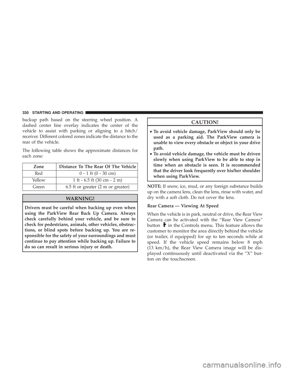
backup path based on the steering wheel position. A
dashed center line overlay indicates the center of the
vehicle to assist with parking or aligning to a hitch/
receiver. Different colored zones indicate the distance to the
rear of the vehicle.
The following table shows the approximate distances for
each zone:
Zone Distance To The Rear Of The VehicleRed 0 - 1 ft (0 - 30 cm)
Yellow 1 ft - 6.5 ft (30 cm - 2 m)
Green 6.5 ft or greater (2 m or greater)
WARNING!
Drivers must be careful when backing up even when
using the ParkView Rear Back Up Camera. Always
check carefully behind your vehicle, and be sure to
check for pedestrians, animals, other vehicles, obstruc-
tions, or blind spots before backing up. You are re-
sponsible for the safety of your surroundings and must
continue to pay attention while backing up. Failure to
do so can result in serious injury or death.
CAUTION!
• To avoid vehicle damage, ParkView should only be
used as a parking aid. The ParkView camera is
unable to view every obstacle or object in your drive
path.
• To avoid vehicle damage, the vehicle must be driven
slowly when using ParkView to be able to stop in
time when an obstacle is seen. It is recommended
that the driver look frequently over his/her shoulder
when using ParkView.
NOTE: If snow, ice, mud, or any foreign substance builds
up on the camera lens, clean the lens, rinse with water, and
dry with a soft cloth. Do not cover the lens.
Rear Camera — Viewing At Speed
When the vehicle is in park, neutral or drive, the Rear View
Camera can be activated with the “Rear View Camera”
button
in the Controls menu. This feature allows the
customer to monitor the area directly behind the vehicle
(or trailer, if equipped) for up to ten seconds while at
speed. If the vehicle speed remains below 8 mph
(13 km/h), the Rear View Camera image will be dis-
played continuously until deactivated via the “X” but-
ton on the touchscreen.
330 STARTING AND OPERATING
Page 345 of 572
WARNING!
•Do not connect trailer brakes to your vehicle’s hy-
draulic brake lines. It can overload your brake sys-
tem and cause it to fail. You might not have brakes
when you need them and could have an accident.
• Towing any trailer will increase your stopping dis-
tance. When towing, you should allow for additional
space between your vehicle and the vehicle in front
of you. Failure to do so could result in an accident.
CAUTION!
If the trailer weighs more than 1,000 lbs (453 kg)
loaded, it should have its own brakes and they should
be of adequate capacity. Failure to do this could lead to
accelerated brake lining wear, higher brake pedal
effort, and longer stopping distances.
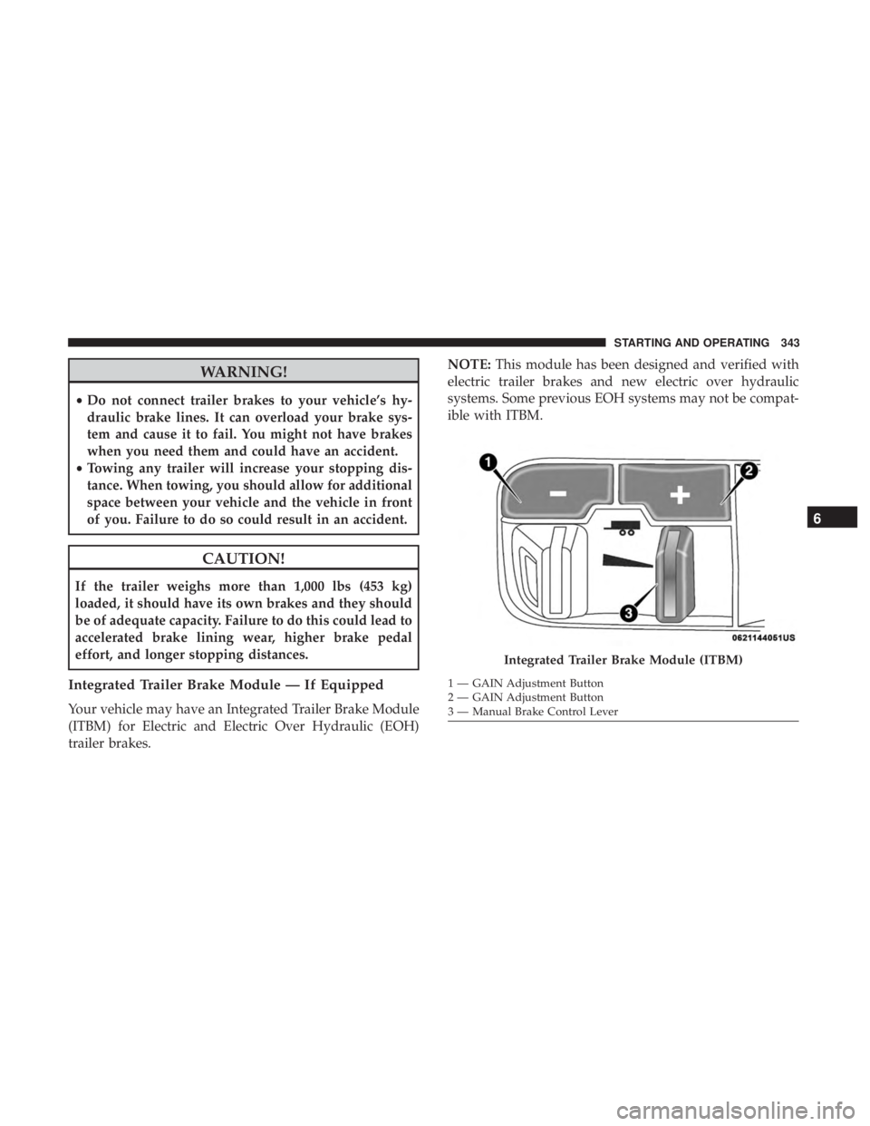
Integrated Trailer Brake Module — If Equipped
Your vehicle may have an Integrated Trailer Brake Module
(ITBM) for Electric and Electric Over Hydraulic (EOH)
trailer brakes. NOTE:
This module has been designed and verified with
electric trailer brakes and new electric over hydraulic
systems. Some previous EOH systems may not be compat-
ible with ITBM.
Integrated Trailer Brake Module (ITBM)
1 — GAIN Adjustment Button
2 — GAIN Adjustment Button
3 — Manual Brake Control Lever
6
STARTING AND OPERATING 343
Page 347 of 572
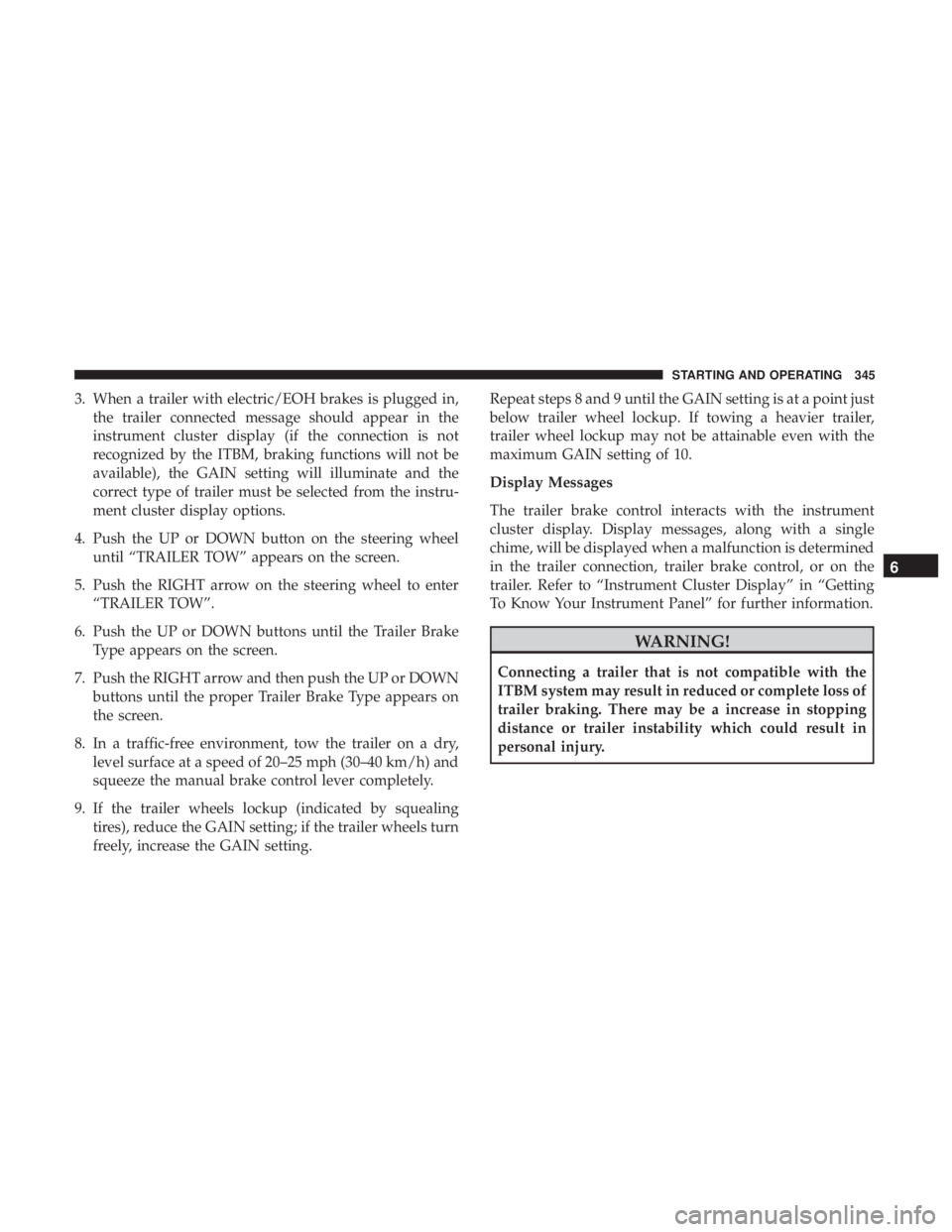
3. When a trailer with electric/EOH brakes is plugged in,the trailer connected message should appear in the
instrument cluster display (if the connection is not
recognized by the ITBM, braking functions will not be
available), the GAIN setting will illuminate and the
correct type of trailer must be selected from the instru-
ment cluster display options.
4. Push the UP or DOWN button on the steering wheel until “TRAILER TOW” appears on the screen.
5. Push the RIGHT arrow on the steering wheel to enter “TRAILER TOW”.
6. Push the UP or DOWN buttons until the Trailer Brake Type appears on the screen.
7. Push the RIGHT arrow and then push the UP or DOWN buttons until the proper Trailer Brake Type appears on
the screen.
8. In a traffic-free environment, tow the trailer on a dry, level surface at a speed of 20–25 mph (30–40 km/h) and
squeeze the manual brake control lever completely.
9. If the trailer wheels lockup (indicated by squealing tires), reduce the GAIN setting; if the trailer wheels turn
freely, increase the GAIN setting. Repeat steps 8 and 9 until the GAIN setting is at a point just
below trailer wheel lockup. If towing a heavier trailer,
trailer wheel lockup may not be attainable even with the
maximum GAIN setting of 10.
Display Messages
The trailer brake control interacts with the instrument
cluster display. Display messages, along with a single
chime, will be displayed when a malfunction is determined
in the trailer connection, trailer brake control, or on the
trailer. Refer to “Instrument Cluster Display” in “Getting
To Know Your Instrument Panel” for further information.
WARNING!
Connecting a trailer that is not compatible with the
ITBM system may result in reduced or complete loss of
trailer braking. There may be a increase in stopping
distance or trailer instability which could result in
personal injury.
6
STARTING AND OPERATING 345
Page 482 of 572
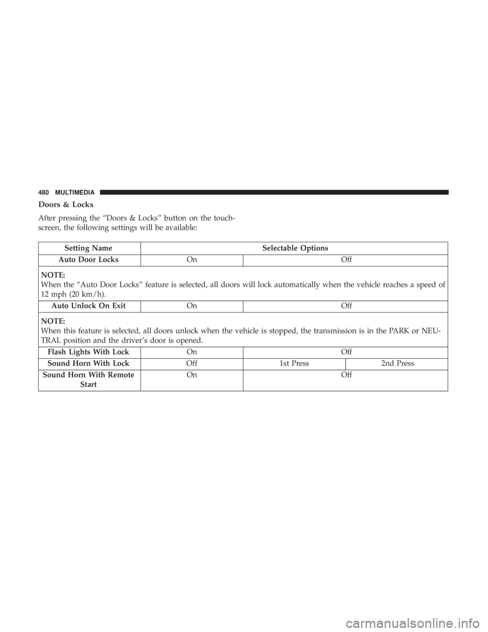
Doors & Locks
After pressing the “Doors & Locks” button on the touch-
screen, the following settings will be available:
Setting NameSelectable Options
Auto Door Locks On Off
NOTE:
When the “Auto Door Locks” feature is selected, all doors will lock automatically when the vehicle reaches a speed of
12 mph (20 km/h). Auto Unlock On Exit On Off
NOTE:
When this feature is selected, all doors unlock when the vehicle is stopped, the transmission is in the PARK or NEU-
TRAL position and the driver’s door is opened. Flash Lights With Lock On Off
Sound Horn With Lock Off1st Press 2nd Press
Sound Horn With Remote Start On
Off
480 MULTIMEDIA
Page 501 of 572
The following options can be selected:
•Pressing the STOP button will freeze the graph. Selecting
Play will clear the graph and restart the process over.
• Press the “+” or “–” buttons to change the history of the
graph. The selectable options are 30, 60, 90, and 120
seconds. The graph will expand or constrict depending
on the setting selected.
• Select the “Gear” display (if equipped) to turn the graph
gear markers on and off.
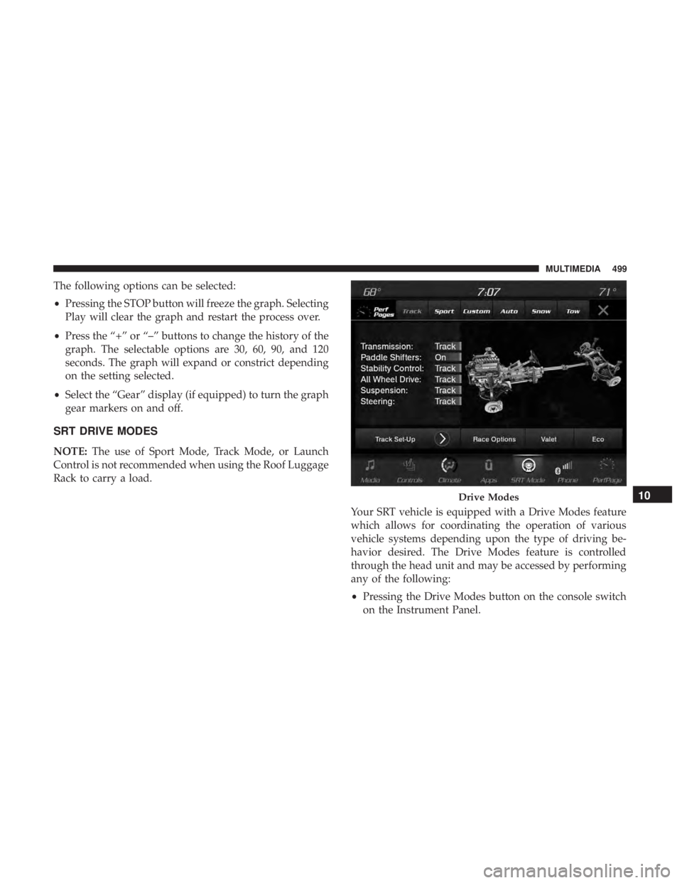
SRT DRIVE MODES
NOTE: The use of Sport Mode, Track Mode, or Launch
Control is not recommended when using the Roof Luggage
Rack to carry a load.
Your SRT vehicle is equipped with a Drive Modes feature
which allows for coordinating the operation of various
vehicle systems depending upon the type of driving be-
havior desired. The Drive Modes feature is controlled
through the head unit and may be accessed by performing
any of the following:
•Pressing the Drive Modes button on the console switch
on the Instrument Panel.
Drive Modes10
MULTIMEDIA 499
Page 534 of 572

NOTE:If you see the NAV icon on the bottom bar, or in the
Apps menus, of your touchscreen, you have the Uconnect
4C NAV system. If not, you have a Uconnect 4C system.
Get Started
All you need to control your Uconnect system with your
voice are the buttons on your steering wheel.
Helpful hints for using Voice Recognition:
• Visit UconnectPhone.com to check mobile device and
feature compatibility and to find phone pairing instruc-
tions.
• Reduce background noise. Wind and passenger conver-
sations are examples of noise that may impact recogni-
tion.
• Speak clearly at a normal pace and volume while facing
straight ahead. The microphone is positioned on the
rearview mirror and aimed at the driver.
• Each time you give a Voice Command, you must first
push either the Voice Recognition (VR) or Phone button,
wait until afterthe beep, then say your Voice Command.
• You can interrupt the help message or system prompts
by pushing the VR or Phone button and saying a Voice
Command from the current category.
Basic Voice Commands
The basic Voice Commands below can be given at any
point while using your Uconnect system.
Push the VR button
. After the beep, say:
• “Cancel” to stop a current voice session
• “Help” to hear a list of suggested Voice Commands
Uconnect Voice Command Buttons
1 — Push To Initiate Or To Answer A Phone Call, Send Or Receive
A Text
2 — For All Radios: Push To Begin Voice Commands
3 — Push To End Call
532 MULTIMEDIA