warning light DODGE DURANGO SRT 2019 Repair Manual
[x] Cancel search | Manufacturer: DODGE, Model Year: 2019, Model line: DURANGO SRT, Model: DODGE DURANGO SRT 2019Pages: 572, PDF Size: 6.59 MB
Page 287 of 572
•If the button is continually pushed, the set speed will
continue to decrease until the button is released, then the
new set speed will be established.
Metric Speed (km/h)
• Pushing the SET (-)button once will result in a 1 km/h
decrease in set speed. Each subsequent tap of the button
results in a decrease of 1 km/h.
• If the button is continually pushed, the set speed will
continue to decrease until the button is released, then the
new set speed will be established.
To Accelerate For Passing
Press the accelerator as you would normally. When the
pedal is released, the vehicle will return to the set speed.
Using Speed Control On Hills
The transmission may downshift on hills to maintain the
vehicle set speed.
NOTE: The Speed Control system maintains speed up and
down hills. A slight speed change on moderate hills is
normal.
On steep hills, a greater speed loss or gain may occur so it
may be preferable to drive without Speed Control.
WARNING!
Speed Control can be dangerous where the system
cannot maintain a constant speed. Your vehicle could
go too fast for the conditions, and you could lose
control and have an accident. Do not use Speed Control
in heavy traffic or on roads that are winding, icy,
snow-covered or slippery.
To Resume Speed
To resume a previously set speed, push the RES button and
release. Resume can be used at any speed above 20 mph
(32 km/h).
To Deactivate
A soft tap on the brake pedal, pushing the CANC button,
or normal brake pressure while slowing the vehicle will
deactivate the Speed Control without erasing the set speed
from memory.
Pushing the on/off button or turning the ignition switch
OFF erases the set speed from memory.
6
STARTING AND OPERATING 285
Page 288 of 572
ADAPTIVE CRUISE CONTROL (ACC) —
IF EQUIPPED
Adaptive Cruise Control (ACC) increases the driving con-
venience provided by cruise control while traveling on
highways and major roadways. However, it is not a safety
system and not designed to prevent collisions.Speed
Control function performs differently. Please refer to the
proper section within this chapter.
ACC will allow you to keep cruise control engaged in light
to moderate traffic conditions without the constant need to
reset your cruise control. ACC utilizes a radar sensor and a
forward facing camera designed to detect a vehicle directly
ahead of you.
NOTE:
• If the sensor does not detect a vehicle ahead of you, ACC
will maintain a fixed set speed.
• If the ACC sensor detects a vehicle ahead, ACC will
apply limited braking or accelerate (not to exceed the
original set speed) automatically to maintain a preset
following distance, while matching the speed of the
vehicle ahead. The Cruise Control system has two control modes:
•
Adaptive Cruise Control mode for maintaining an ap-
propriate distance between vehicles.
• Normal (Fixed Speed) Cruise Control mode for cruising
at a constant preset speed. For additional information,
refer to “Normal (Fixed Speed) Cruise Control Mode” in
this section.
NOTE: Normal (Fixed Speed) Cruise Control will not react
to preceding vehicles. Always be aware of the mode
selected.
You can change the mode by using the Cruise Control
buttons. The two control modes function differently. Al-
ways confirm which mode is selected.
WARNING!
• Adaptive Cruise Control (ACC) is a convenience
system. It is not a substitute for active driving
involvement. It is always the driver ’s responsibility
to be attentive of road, traffic, and weather condi-
tions, vehicle speed, distance to the vehicle ahead;
and, most importantly, brake operation to ensure safe
(Continued)
286 STARTING AND OPERATING
Page 297 of 572
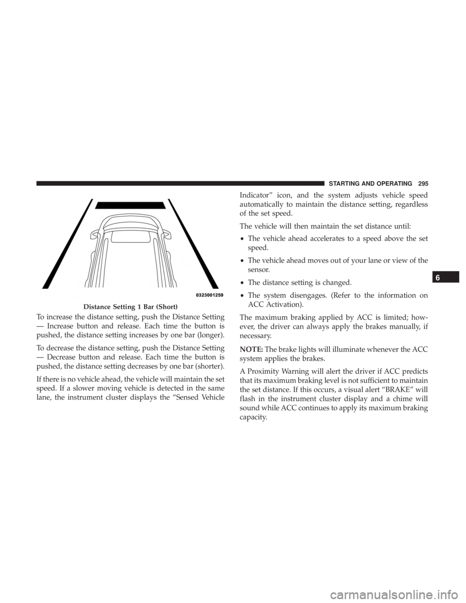
To increase the distance setting, push the Distance Setting
— Increase button and release. Each time the button is
pushed, the distance setting increases by one bar (longer).
To decrease the distance setting, push the Distance Setting
— Decrease button and release. Each time the button is
pushed, the distance setting decreases by one bar (shorter).
If there is no vehicle ahead, the vehicle will maintain the set
speed. If a slower moving vehicle is detected in the same
lane, the instrument cluster displays the “Sensed VehicleIndicator” icon, and the system adjusts vehicle speed
automatically to maintain the distance setting, regardless
of the set speed.
The vehicle will then maintain the set distance until:
•
The vehicle ahead accelerates to a speed above the set
speed.
• The vehicle ahead moves out of your lane or view of the
sensor.
• The distance setting is changed.
• The system disengages. (Refer to the information on
ACC Activation).
The maximum braking applied by ACC is limited; how-
ever, the driver can always apply the brakes manually, if
necessary.
NOTE: The brake lights will illuminate whenever the ACC
system applies the brakes.
A Proximity Warning will alert the driver if ACC predicts
that its maximum braking level is not sufficient to maintain
the set distance. If this occurs, a visual alert “BRAKE” will
flash in the instrument cluster display and a chime will
sound while ACC continues to apply its maximum braking
capacity.
Distance Setting 1 Bar (Short)
6
STARTING AND OPERATING 295
Page 306 of 572
To change between the different control modes, push the
Adaptive Cruise Control (ACC) on/off button which turns
the ACC and the Normal (Fixed Speed) Cruise Control off.
Pushing the Normal (Fixed Speed) Cruise Control on/off
button will result in turning on (changing to) the Normal
(Fixed Speed) Cruise Control mode.
WARNING!
In the Normal (Fixed Speed) Cruise Control mode, the
system will not react to vehicles ahead. In addition, the
proximity warning does not activate and no alarm will
sound even if you are too close to the vehicle ahead
since neither the presence of the vehicle ahead nor the
vehicle-to-vehicle distance is detected. Be sure to main-
tain a safe distance between your vehicle and the
vehicle ahead. Always be aware which mode is se-
lected.
To Set A Desired Speed
Turn the Normal (Fixed Speed) Cruise Control
on. When the vehicle has reached the desired
speed, push the SET (+) or SET (-) button and
release. Release the accelerator and the vehicle
will operate at the selected speed. Once a speed has been set a message “CRUISE CONTROL SET TO MPH (km/h)”
will appear indicating what speed was set. This light will
turn on when the system is turned on via the on/off
control. It turns green when the cruise control is set.
To Vary The Speed Setting
To Increase Speed
When the Normal (Fixed Speed) Cruise Control is set, you
can increase speed by pushing the SET
(+)button.
The driver’s preferred units can be selected through the
instrument cluster display. Refer to “Getting To Know Your
Instrument Panel” for more information. The speed incre-
ment shown is dependant on the speed of U.S. (mph) or
Metric (km/h) units:
U.S. Speed (mph)
• Pushing the SET (+)button once will result ina1mph
increase in set speed. Each subsequent tap of the button
results in an increase of 1 mph.
• If the button is continually pushed, the set speed will
continue to increase in 5 mph increments until the
button is released. The increase in set speed is reflected
in the instrument cluster display.
304 STARTING AND OPERATING
Page 334 of 572
5. Fill the vehicle with fuel – when the fuel nozzle “clicks”or shuts off the fuel tank is full.
6. Wait five seconds before removing the fuel nozzle to allow fuel to drain from nozzle.
7. Remove the fuel nozzle and close the fuel door.
Emergency Gas Can Refueling
• Most gas cans will not open the flapper door.
• A funnel is provided to open the flapper door to allow
emergency refueling with a gas can.
• Retrieve funnel from the spare tire storage area.
• Insert funnel into same filler pipe opening as the fuel
nozzle.
• Ensure funnel is inserted fully to hold flapper door
open.
• Pour fuel into funnel opening.
• Remove funnel from filler pipe, clean off prior to putting
back in the spare tire storage area.WARNING!
• Never have any smoking materials lit in or near the
vehicle when the fuel door is open or the tank is
being filled.
• Never add fuel when the engine is running. This is
in violation of most state and federal fire regulations
and may cause the “Malfunction Indicator Light” to
turn on.
• A fire may result if fuel is pumped into a portable
container that is inside of a vehicle. You could be
burned. Always place fuel containers on the ground
while filling.
CAUTION!
To avoid fuel spillage and overfilling, do not “top off”
the fuel tank after filling.
Emergency Fuel Filler Door Release
If you are unable to open the fuel filler door, use the fuel
filler door emergency release.
1. Open the liftgate.
332 STARTING AND OPERATING
Page 339 of 572
Weight-Distributing Hitch
A weight-distributing system works by applying leverage
through spring (load) bars. They are typically used for
heavier loads to distribute trailer tongue weight to the tow
vehicle’s front axle and the trailer axle(s). When used in
accordance with the manufacturer’s directions, it provides
for a more level ride, offering more consistent steering and
brake control thereby enhancing towing safety. The addi-
tion of a friction/hydraulic sway control also dampens
sway caused by traffic and crosswinds and contributes
positively to tow vehicle and trailer stability. Trailer sway
control and a weight distributing (load equalizing) hitch
are recommended for heavier Tongue Weights (TW) and
may be required depending on vehicle and trailer
configuration/loading to comply with Gross Axle Weight
Rating (GAWR) requirements.
WARNING!
•An improperly adjusted Weight Distributing Hitch
system may reduce handling, stability, braking per-
formance, and could result in a collision.
• Weight Distributing Systems may not be compatible
with Surge Brake Couplers. Consult with your hitch
and trailer manufacturer or a reputable Recreational
Vehicle dealer for additional information.
Trailer Hitch Classification
The following chart provides the industry standard for the
maximum trailer weight a given trailer hitch class can tow
and should be used to assist you in selecting the correct
trailer hitch for your intended towing condition.
Trailer Hitch Classification Definitions
Class Max. Trailer Hitch Industry Standards
Class I - Light Duty 2,000 lbs (907 kg)
Class II - Medium Duty 3,500 lbs (1,587 kg)
Class III - Heavy Duty 5,000 lbs (2,267 kg)
6
STARTING AND OPERATING 337
Page 352 of 572
•Maintain sufficient distance between your vehicle and
the vehicle in front of you to avoid a collision in a
sudden stop.
Driving Through Water
Driving through water more than a few inches/centimeters
deep will require extra caution to ensure safety and pre-
vent damage to your vehicle.
Flowing/Rising Water
WARNING!
Do not drive on or across a road or path where water is
flowing and/or rising (as in storm run-off). Flowing
water can wear away the road or path’s surface and
cause your vehicle to sink into deeper water. Further-
more, flowing and/or rising water can carry your ve-
hicle away swiftly. Failure to follow this warning may
result in injuries that are serious or fatal to you, your
passengers, and others around you.
Shallow Standing Water
Although your vehicle is capable of driving through shal-
low standing water, consider the following Cautions and
Warnings before doing so.
WARNING!
• Driving through standing water limits your vehicle’s
traction capabilities. Do not exceed 5 mph (8 km/h)
when driving through standing water.
• Driving through standing water limits your vehicle’s
braking capabilities, which increases stopping dis-
tances. Therefore, after driving through standing
water, drive slowly and lightly press on the brake
pedal several times to dry the brakes.
• Failure to follow these warnings may result in inju-
ries that are serious or fatal to you, your passengers,
and others around you.
350 STARTING AND OPERATING
Page 357 of 572
WARNING!
ALWAYS obey traffic laws and pay attention to the
road. ALWAYS drive safely with your hands on the
steering wheel. You have full responsibility and as-
sume all risks related to the use of the features and
applications in this vehicle. Only use the features and
applications when it is safe to do so. Failure to do so
may result in an accident involving serious injury or
death.
NOTE:
• Your vehicle may be transmitting data as authorized by
the subscriber.
• The SOS and ASSIST buttons will only function if you
are connected to an operable LTE (voice/data) or 4G
(data) network. Other Uconnect services will only be
operable if your SiriusXM Guardian service is active and
you are connected to an operable LTE (voice/data) or 4G
(data) network. ASSIST Call
The ASSIST Button is used to automatically connect you to
any one of the following support centers:
•
Roadside Assistance – If you get a flat tire, or need a tow,
just push the ASSIST button and you will be connected
to a representative for assistance. Roadside Assistance
will know what vehicle you’re driving and its location.
Additional fees may apply for roadside assistance.
• SiriusXM Guardian Customer Care – In-vehicle support
for SiriusXM Guardian.
• Vehicle Customer Care – Total support for all other
vehicle issues.
SOS Call
1. Push the SOS Call button on the Rearview Mirror.
NOTE: In case the SOS Call button is pushed in error, there
will be a ten second delay before the SOS Call system
initiates a call to a SOS operator. To cancel the SOS Call
connection, push the SOS call button on the Rearview
Mirror or press the cancellation button on the Device
Screen. Termination of the SOS Call will turn off the green
LED light on the Rearview Mirror.
7
IN CASE OF EMERGENCY 355
Page 358 of 572
2. The LED light located between the ASSIST and SOSbuttons on the Rearview Mirror will turn green once a
connection to a SOS operator has been made.
3. Once a connection between the vehicle and a SOS operator is made, the SOS Call system may transmit the
following important vehicle information to a SOS op-
erator:
• Indication that the occupant placed a SOS Call.
• The vehicle brand.
• The last known GPS coordinates of the vehicle.
4. You should be able to speak with the SOS operator through the vehicle audio system to determine if addi-
tional assistance is needed.
WARNING!
ALWAYS obey traffic laws and pay attention to the road.
ALWAYS drive safely with your hands on the steering
wheel. You have full responsibility and assume all risks
related to the use of the features and applications in this
vehicle. Only use the features and applications when it
is safe to do so. Failure to do so may result in an accident
involving serious injury or death.
NOTE:
•Your vehicle may be transmitting data as authorized
by the subscriber.
• Once a connection is made between the vehicle’s SOS
Call system and the SOS operator, the SOS operator
may be able to open a voice connection with the
vehicle to determine if additional assistance is needed.
Once the SOS operator opens a voice connection with
the vehicle’s SOS Call system, the operator should be
able to speak with you or other vehicle occupants and
hear sounds occurring in the vehicle. The vehicle’s
SOS Call system will attempt to remain connected
with the SOS operator until the SOS operator termi-
nates the connection.
5. The SOS operator may attempt to contact appropriate emergency responders and provide them with impor-
tant vehicle information and GPS coordinates.
WARNING!
•If anyone in the vehicle could be in danger (e.g., fire
or smoke is visible, dangerous road conditions or
location), do not wait for voice contact from an
(Continued)
356 IN CASE OF EMERGENCY
Page 359 of 572
WARNING!(Continued)
Emergency Services Agent. All occupants should exit
the vehicle immediately and move to a safe location.
•
Never place anything on or near the vehicle’s operable
network and GPS antennas. You could prevent oper-
able network and GPS signal reception, which can
prevent your vehicle from placing an emergency call.
An operable network and GPS signal reception is
required for the SOS Call system to function properly.
• The SOS Call system is embedded into the vehicle’s
electrical system. Do not add aftermarket electrical
equipment to the vehicle’s electrical system. This
may prevent your vehicle from sending a signal to
initiate an emergency call. To avoid interference that
can cause the SOS Call system to fail, never add
aftermarket equipment (e.g., two-way mobile radio,
CB radio, data recorder, etc.) to your vehicle’s electri-
cal system or modify the antennas on your vehicle. IF
YOUR VEHICLE LOSES BATTERY POWER FOR
ANY REASON (INCLUDING DURING OR AFTER
AN ACCIDENT), THE UCONNECT FEATURES,
APPS AND SERVICES, AMONG OTHERS, WILL
NOT OPERATE.
(Continued)
WARNING! (Continued)
•Modifications to any part of the SOS Call system
could cause the air bag system to fail when you need
it. You could be injured if the air bag system is not
there to help protect you.
SOS Call System Limitations
Vehicles sold in Mexico DO NOThave SOS Call system
capabilities.
SOS or other emergency line operators in Mexico may not
answer or respond to SOS system calls.
If the SOS Call system detects a malfunction, any of the
following may occur at the time the malfunction is de-
tected, and at the beginning of each ignition cycle:
• The Rearview Mirror light located between the ASSIST
and SOS buttons will continuously be illuminated red.
• The Device Screen will display the following message
“Vehicle device requires service. Please contact your
dealer.”
• An In-Vehicle Audio message will state “Vehicle device
requires service. Please contact your dealer.”
7
IN CASE OF EMERGENCY 357