sensor DODGE GRAND CARAVAN 2004 Owners Manual
[x] Cancel search | Manufacturer: DODGE, Model Year: 2004, Model line: GRAND CARAVAN, Model: DODGE GRAND CARAVAN 2004Pages: 397, PDF Size: 7.59 MB
Page 35 of 397
WARNING!During power operation, personal injury or cargo
damage may occur. Ensure the liftgate travel path is
clear. Make sure the liftgate is closed and latched
before driving away.
NOTE:
² If anything obstructs the power liftgate while it is
closing or opening, the liftgate will automatically
reverse to the closed or open position, provided it
meets sufficient resistance.
² There are also pinch sensors attached to the side of the
liftgate opening. Light pressure anywhere along these
strips will cause the liftgate to return to the open
position. ² The power liftgate must be in the full open or close
positions for any of the buttons to operate. If the
liftgate is not in the full open or close positions it must
be opened or closed manually.
² If the liftgate release button is activated while the
power liftgate is closing, the liftgate will reverse to the
full open position.
² The power liftgate buttons will not operate if the
vehicle is in gear or the vehicle speed is above 0 mph
(0 km/h).
² The power liftgate will not operate in temperatures
below 2 12ÉF ( 2 24ÉC) or temperatures above 143ÉF
(62ÉC). Be sure to remove any build-up of snow or ice
from the liftgate before pressing any of the power
liftgate buttons. THINGS TO KNOW BEFORE STARTING YOUR VEHICLE 35
2
Page 52 of 397

WARNING!² Relying on the airbags alone could lead to more
severe injuries in a collision. The airbags work
with your seat belt to restrain you properly. In
some collisions the airbags won't deploy at all.
Always wear your seat belts even though you
have airbags.
² Being too close to the steering wheel or instru-
ment panel during front airbag deployment could
cause serious injury. Airbags need room to inflate.
Sit back, comfortably extending your arms to
reach the steering wheel or instrument panel.
² If the vehicle has side airbags, they also need
room to inflate. Do not lean against the door. Sit
upright in the center of the seat. The Front Airbag System consists of the following:
² Front Airbag Control Module (with integrated side
impact sensor - if equipped)
² AIRBAG Readiness Light
² Driver Airbag
² Front Passenger Airbag
² Steering Wheel and Column
² Instrument Panel
² Seat Belt Readiness Light
² Front Seat Belt Pretensioners
² Interconnecting Wiring
² Knee Impact Bolster52 THINGS TO KNOW BEFORE STARTING YOUR VEHICLE
Page 54 of 397
² When the front airbag control module detects a colli-
sion requiring the front airbags, it signals the inflator
units. A large quantity of nontoxic gas is generated to
inflate the front airbags. Different front airbag inflation
rates are possible, these rates are determined by the
front airbag control module based on collision severity.
The front airbag covers separate and fold out of the
way as the airbags inflate to their full size. The front
airbags fully inflate in about 50 milliseconds. This is
only about half of the time it takes you to blink your
eyes. The front airbags then quickly deflate while
helping to restrain the driver and front passenger. The
driver's and passenger's front airbag gas is vented
through the airbag material towards the instrument
panel. In this way the front airbags do not interfere
with your control of the vehicle.
² The Knee Impact Bolsters help protect the knees and
position you for the best interaction with the front
airbags. Side Airbags Supplemental Restraint System
(SRS) Ð If Equipped
The Side Airbag System, if equipped, consists of the
following:
² AIRBAG Readiness Light (shared with the front airbag
system)
² Side Airbag in the driver's seat
² Side Airbag in the passenger's seat
² Front Airbag Control Module (with integrated side
impact sensor - if equipped)
² Interconnecting Wiring
How The Side Airbag System Works
The front airbag control modules determine if a side
collision is severe enough to require the side airbags to
inflate. The front airbag control modules will not detect
roll over, or rear collisions.54 THINGS TO KNOW BEFORE STARTING YOUR VEHICLE
Page 116 of 397
NOTE: Tire pressure menu items are available only on
vehicles equipped with the Tire Pressure Monitor Sys-
tem.
Customer Programmable Features Ð If Equipped
Press the ªMENUº button until one of the display choices
following appears:
Language
When in this display you may select one of five lan-
guages for all display nomenclature, including the trip
computer functions. Press the ªSTEPº button while in
this display selects English, Francaise, Deutsch, Italiano,
or Espanol. As you continue the displayed information
will be shown in the selected language.
US or Metric
Pressing the ªSTEPº button when in this display selects
US or Metric. The overhead console and climate control
displays will be in the selected units. Service Interval
When this feature is selected a service interval between
2,000 miles (3 200 km) and 6,000 miles (9 600 km) in 500
mile (800 km) increments may be selected. Pressing the
ªSTEPº button when in this display will select distances
between 2,000 miles (3 200 km) and 6,000 miles (9 600
km) in 500 mile (800 km) increments.
Reset Service Distance (Displays Only if Service
Interval was Changed)
When this feature is selected the current accumulated
service distance can be reset to the newly selected service
interval. Pressing the ªSTEPº button when in this display
will select ªYesº or ªNo.º
Retrain Tire Sensors (Available with Tire Pressure
Monitor System Only)
The Tire Pressure Monitor system must be retrained
following a tire rotation or wheel rim mounted sensor
replacement. If you unintentionally choose ªYesº to train116 UNDERSTANDING THE FEATURES OF YOUR VEHICLE
Page 157 of 397
20. Odometer/Trip Odometer
The odometer shows the total distance the vehicle has
been driven.
U.S. federal regulations require that upon transfer of
vehicle ownership, the seller certify to the purchaser the
correct mileage that the vehicle has been driven. There-
fore, if the odometer reading is changed during repair or
replacement, be sure to keep a record of the reading
before and after the service so that the correct mileage can
be determined.
The trip odometer shows individual trip mileage. To
switch from odometer to trip odometer, press the Trip
Odometer button.
21. Cruise Indicator
This vacuum fluorescent display indicator shows that the
Speed Control System is ON. 22. Trip Odometer Button
Press this button to change the display from odometer to
trip odometer. The word TRIP will appear when in the
trip odometer mode.
Push in and hold the button for two seconds to reset the
trip odometer to 0 miles or kilometers. The odometer
must be in trip mode to reset.
23. Tire Pressure Monitor Warning Light Ð If
Equipped
This light will turn on when there is a Low tire
pressure condition. The light will also turn on
if a problem exist with any tire sensor. The light
will remain on until the tire pressure is prop-
erly set or the problem with the sensor is corrected.
This light will turn on momentarily as a bulb check when
the engine is started. UNDERSTANDING YOUR INSTRUMENT PANEL 157
4
Page 208 of 397
temperature selection follows the setting of the driv-
er's temperature control on the front climate control
unit. The rear mode selection follows the setting of the
front mode control.
Rear Economy Mode
If rear economy mode is desired, set the center knob on
the front control unit to the ªREARº position. Turn the
A/C button OFF and select any mode except ªMIXº or
ªDEFROSTº.
The rear temperature knob and the rear blower speed can
be adjusted as desired by the second seat occupants.
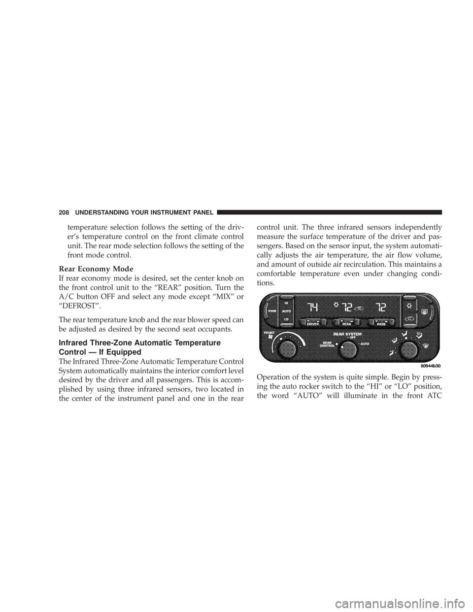
Infrared Three-Zone Automatic Temperature
Control Ð If Equipped
The Infrared Three-Zone Automatic Temperature Control
System automatically maintains the interior comfort level
desired by the driver and all passengers. This is accom-
plished by using three infrared sensors, two located in
the center of the instrument panel and one in the rear control unit. The three infrared sensors independently
measure the surface temperature of the driver and pas-
sengers. Based on the sensor input, the system automati-
cally adjusts the air temperature, the air flow volume,
and amount of outside air recirculation. This maintains a
comfortable temperature even under changing condi-
tions.
Operation of the system is quite simple. Begin by press-
ing the auto rocker switch to the ªHIº or ªLOº position,
the word ªAUTOº will illuminate in the front ATC208 UNDERSTANDING YOUR INSTRUMENT PANEL
Page 259 of 397
Improper alignment will not cause vehicle vibration.
Vibration may be a result of tire and wheel out-of-
balance. Proper balancing will reduce vibration and
avoid tire cupping and spotty wear.
ALL WHEEL DRIVE (AWD) Ð IF EQUIPPED
CAUTION!All Wheel Drive (AWD) vehicles must have the same
size and type tires on all wheel positions. Unequal
tire sizes must not be used. Unequal tire size may
cause failure of the power transfer unit and/or the
viscous coupling. TIRE PRESSURE MONITOR SYSTEM Ð IF
EQUIPPED
The Tire Pressure Monitor System (TPM) system uses
wireless technology with wheel rim mounted electronic
sensors to monitor tire pressure levels (EXCLUDING
THE SPARE TIRE). Sensors, mounted to each wheel as
part of the valve stem, transmit tire pressure readings to
a receiver located in the overhead console.
NOTE: The tire pressure monitoring system on your
vehicle will warn you when one of your tires is signifi-
cantly underinflated and when some combinations of
your tires are significantly underinflated. However, there
are other combinations of significantly underinflated
tires for which your tire pressure monitoring system may
not warn you. These other combinations are relatively
common, accounting for approximately half the instances
in which vehicles have significantly underinflated tires.
For example, your system may not warn you when both
tires on the same side or on the same axle of your vehicle STARTING AND OPERATING 259
5
Page 261 of 397
TIRE PRESSURE NOW AVAILABLE
The TPM system is functioning normally and the external
interference is no longer affecting the system.
SPARE TIRE IN USE? YES/NO
The TPM system requires more information to determine
the correct mode of operation, one or more of the vehicle
active tires has been replaced by the spare, a wheel rim
not equipped with a TPM sensor or the TPM system
requires service.
If the spare tire or non TPM sensor equipped wheel rim
is in active use (mounted on the vehicle), answer YES and
the TPM system will resume normal operation.
If the spare tire or non TPM sensor equipped wheel rim
is NOT in active use (mounted on the vehicle), answer
NO and the TPM system will resume normal operation. ALL 5 TIRES WITH CAR? YES/NO
The TPM system requires more information to determine
the correct mode of operation, one or more of the vehicle
active tires has been replaced by the spare, a wheel rim
not equipped with a TPM sensor or the TPM system
requires service.
If the spare tire or non TPM sensor equipped wheel rim
is in active use (mounted on the vehicle), answer YES and
the TPM system will resume normal operation.
If the spare tire or non TPM sensor equipped wheel rim
is NOT in active use (mounted on the vehicle), answer
NO and the TPM system will resume normal operation. STARTING AND OPERATING 261
5
Page 262 of 397
CAUTION!The TPM system has been optimized for the original
equipment tires and wheels. TPM system pressures
have been established for the tire size equipped on
your vehicle. Undesirable operation or sensor dam-
age may result when using replacement equipment
that is not of the same size, type, and/or style.
After-market wheels can cause sensor damage. Do
not use tire sealant or balance beads if your vehicle
is equipped with TPM system as damage to the
sensors may result.
NOTE:
² The TPM system can inform the driver of a low tire
pressure condition of 28 psi [1.9 bars] (193 kPa) or less,
or high a tire pressure condition of 48 psi [3.3 bars]
(330 kPa) or more. ² The TPM system is not intended to replace normal tire
care and maintenance, nor to provide warning of a tire
failure or condition.
² The TPM system should not be used as a tire pressure
gauge while adjusting your tire pressure.
² The TPM system must be retrained after a tire rotation
or wheel rim mounted sensor replacement. See your
authorized dealer for service.
CAUTION!After inspecting or adjusting the tire pressure al-
ways reinstall the valve stem cap. This will prevent
moisture and dirt entry into the valve stem, which
could damage the wheel rim sensor.262 STARTING AND OPERATING
Page 263 of 397
General Information
This device complies with part 15 of the FCC rules and
RSS 210 of Industry Canada. Operation is subject to the
following conditions:
² This device may not cause harmful interference.
² This device must accept any interference received,
including interference that may cause undesired op-
eration.
The tire pressure sensors are covered under one of the
following licenses:
United States ..................... KR5S120123
Canada ........................ 2671-S120123 TIRE CHAINS
Use only compact chains, or other traction aids that meet
SAE type ªClass Sº specifications. Chains must be the
proper size for the vehicle, as recommended by the chain
manufacturer.
NOTE: Do not use tire chains on a compact spare tire. STARTING AND OPERATING 263
5