remove seats DODGE GRAND CARAVAN 2005 User Guide
[x] Cancel search | Manufacturer: DODGE, Model Year: 2005, Model line: GRAND CARAVAN, Model: DODGE GRAND CARAVAN 2005Pages: 480, PDF Size: 15.54 MB
Page 336 of 480

VEHICLE LOADING
The load carrying capacity of your vehicle is shown in the
charts that follow. This information should be used for
passenger and luggage loading as indicated.
If seats are removed for carrying cargo, do not exceed the
specified GVWR and GAWR.
Vehicle Certification Label
Your vehicle has a certification label attached to the
driver ’ s door pillar.
The label contains the following information:
• Name of manufacturer
• Month and year of manufacture
• Gross Vehicle Weight Rating (GVWR)
• Gross Axle Weight Rating (GAWR) front
• Gross Axle Weight Rating (GAWR) rear • Vehicle Identification Number (VIN)
• Type of Vehicle
• Month Day and Hour of Manufacture (MDH)
The bar code allows a computer scanner to read the
Vehicle Identification Number (VIN).
Gross Vehicle Weight Rating (GVWR)
The GVWR is the total allowable weight of your vehicle.
This includes driver, passengers, and cargo. The total
load must be limited so that you do not exceed the
GVWR.
Gross Axle Weight Rating (GAWR)
The GAWR is the maximum capacity of the front and rear
axles. Distribute the load over the front and rear axles
evenly. Make sure that you do not exceed either front or
rear GAWR.336 STARTING AND OPERATING
Page 349 of 480

Spare Tire Stowage — Fold-in-Floor Seating
For vehicles equipped with fold-in-floor seating, the
spare tire is stowed inside a protective cover located
under the center of the vehicle by means of a cable winch
mechanism. The “ spare tire drive ” nut is located on the
floor, under a plastic cap between the front seats.
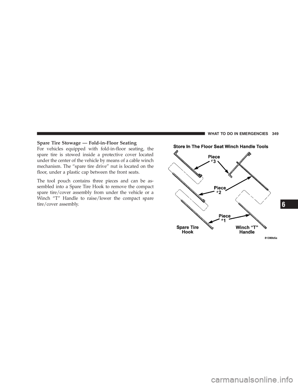
The tool pouch contains three pieces and can be as-
sembled into a Spare Tire Hook to remove the compact
spare tire/cover assembly from under the vehicle or a
Winch “ T ” Handle to raise/lower the compact spare
tire/cover assembly. WHAT TO DO IN EMERGENCIES 349
6
Page 415 of 480

The Heated Mirrors, Lower Instrument Panel Power
Outlet and Removable Floor Console, when in the front
position are fused with self resetting fuses that are only
serviceable by an authorized dealer. The power seats are
fused by a 30 Amp circuit breaker located under the
driver ’ s seat. The Power Windows are fused by a 25 Amp
circuit breaker located under the instrument panel near
the steering column. If you experience temporary or
permanent loss of these systems see your authorized
dealer for service.
VEHICLE STORAGE
If you are leaving your vehicle dormant for more than 21
days you may want to take steps to protect your battery.
You may:
• Remove the 20 Amp mini fuse in the Integrated Power
Module labeled Ignition-Off Draw (IOD).
• Or, disconnect the negative cable from the battery. • Anytime you store your vehicle, or keep it out of
service (i.e. vacation) for two weeks or more, run the
air conditioning system at idle for about five minutes
in the fresh air and high blower setting. This will
insure adequate system lubrication to minimize the
possibility of compressor damage when the system is
started again.
REPLACEMENT LIGHT BULBS
LIGHT BULBS — Interior Bulb Number
Center & Rear Dome Light .................. 578
Center & Rear Reading Lights ............... 578
Front Door Courtesy Light .................. 578
Front Header Reading Lights — If Equipped ..... 578
Instrument Cluster Lights ................. PC74
Liftgate Light(s) .......................... 578
Overhead Console Reading Lights .......... PC579
Removable Console Light — If Equipped ....... 194
Visor Vanity Lights .................... 6501966MAINTAINING YOUR VEHICLE 415
7