mirror DODGE GRAND CARAVAN 2008 5.G User Guide
[x] Cancel search | Manufacturer: DODGE, Model Year: 2008, Model line: GRAND CARAVAN, Model: DODGE GRAND CARAVAN 2008 5.GPages: 531, PDF Size: 7.72 MB
Page 159 of 531
10. Insert the ignition key and turn the ignition switch to
the ON position.
11. Select9Remote Linked to Memory9in the Electronic
Vehicle Information Center (EVIC) and enter9Ye s9or
select9No9from the EVIC and enter9Ye s9. Refer to the
Customer Programmable features in the Electronic Ve-
hicle Information Center (EVIC) section for more infor-
mation.
12. Repeat the above steps to set the next Memory
Position using the other numbered Memory Button or to
link another Remote Keyless Entry transmitter to
memory.
Memory Position Recall
NOTE:The vehicle must be in PARK to recall memory
positions. If a recall is attempted when the vehicle is not
in PARK, a message will be displayed in the Electronic
Vehicle Information Center (EVIC).To recall the memory settings for driver one, press
Memory Button 1 on the driver's door or the UNLOCK
button on the Remote Keyless Entry transmitter linked to
Memory Position 1.
To recall the memory setting for driver two, press
Memory Button 2 on the driver's door or the UNLOCK
button on the Remote Keyless Entry transmitter linked to
Memory Position 2.
A recall can be cancelled by pressing any of the memory
buttons on the driver's door during a recall (S, 1, or 2).
When a recall is cancelled, the driver's seat, driver's
mirror, and the pedals stop moving. A delay of one
second will occur before another recall can be selected.To Disable A RKE Transmitter Linked to Memory
1. Turn the ignition switch to the OFF position and
remove the key.
UNDERSTANDING THE FEATURES OF YOUR VEHICLE 157
3
Page 173 of 531
TILT STEERING COLUMN Ð IF EQUIPPED
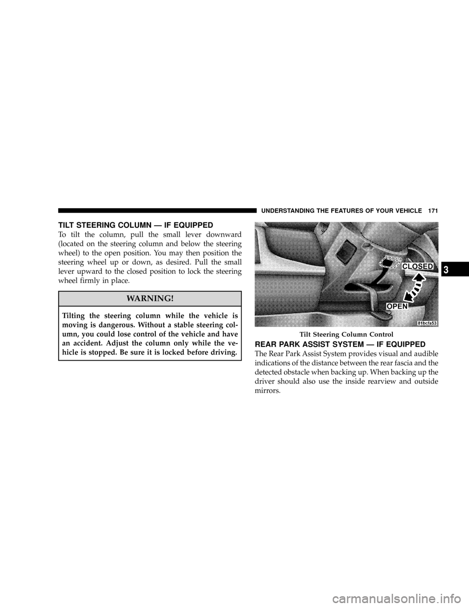
To tilt the column, pull the small lever downward
(located on the steering column and below the steering
wheel) to the open position. You may then position the
steering wheel up or down, as desired. Pull the small
lever upward to the closed position to lock the steering
wheel firmly in place.
WARNING!
Tilting the steering column while the vehicle is
moving is dangerous. Without a stable steering col-
umn, you could lose control of the vehicle and have
an accident. Adjust the column only while the ve-
hicle is stopped. Be sure it is locked before driving.
REAR PARK ASSIST SYSTEM Ð IF EQUIPPED
The Rear Park Assist System provides visual and audible
indications of the distance between the rear fascia and the
detected obstacle when backing up. When backing up the
driver should also use the inside rearview and outside
mirrors.
Tilt Steering Column Control
UNDERSTANDING THE FEATURES OF YOUR VEHICLE 171
3
Page 175 of 531
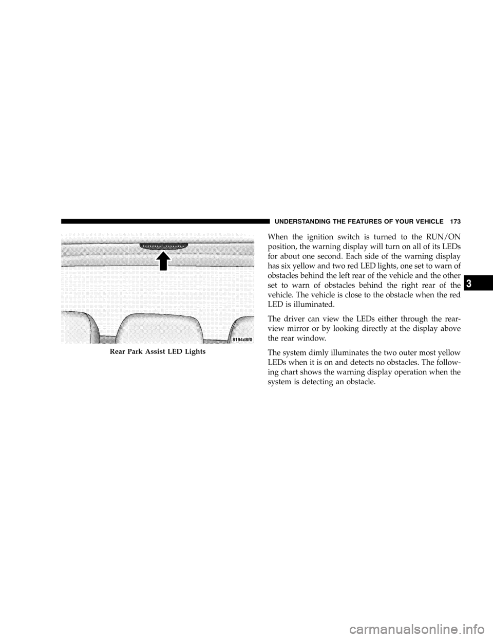
When the ignition switch is turned to the RUN/ON
position, the warning display will turn on all of its LEDs
for about one second. Each side of the warning display
has six yellow and two red LED lights, one set to warn of
obstacles behind the left rear of the vehicle and the other
set to warn of obstacles behind the right rear of the
vehicle. The vehicle is close to the obstacle when the red
LED is illuminated.
The driver can view the LEDs either through the rear-
view mirror or by looking directly at the display above
the rear window.
The system dimly illuminates the two outer most yellow
LEDs when it is on and detects no obstacles. The follow-
ing chart shows the warning display operation when the
system is detecting an obstacle.
Rear Park Assist LED Lights
UNDERSTANDING THE FEATURES OF YOUR VEHICLE 173
3
Page 184 of 531
OVERHEAD CONSOLES
Front Overhead Console Ð If Equipped
Two versions of the overhead console are available. The
base front overhead console models feature fixed incan-
descent courtesy/reading lights, flip-down sunglass stor-
age and conversation mirror.
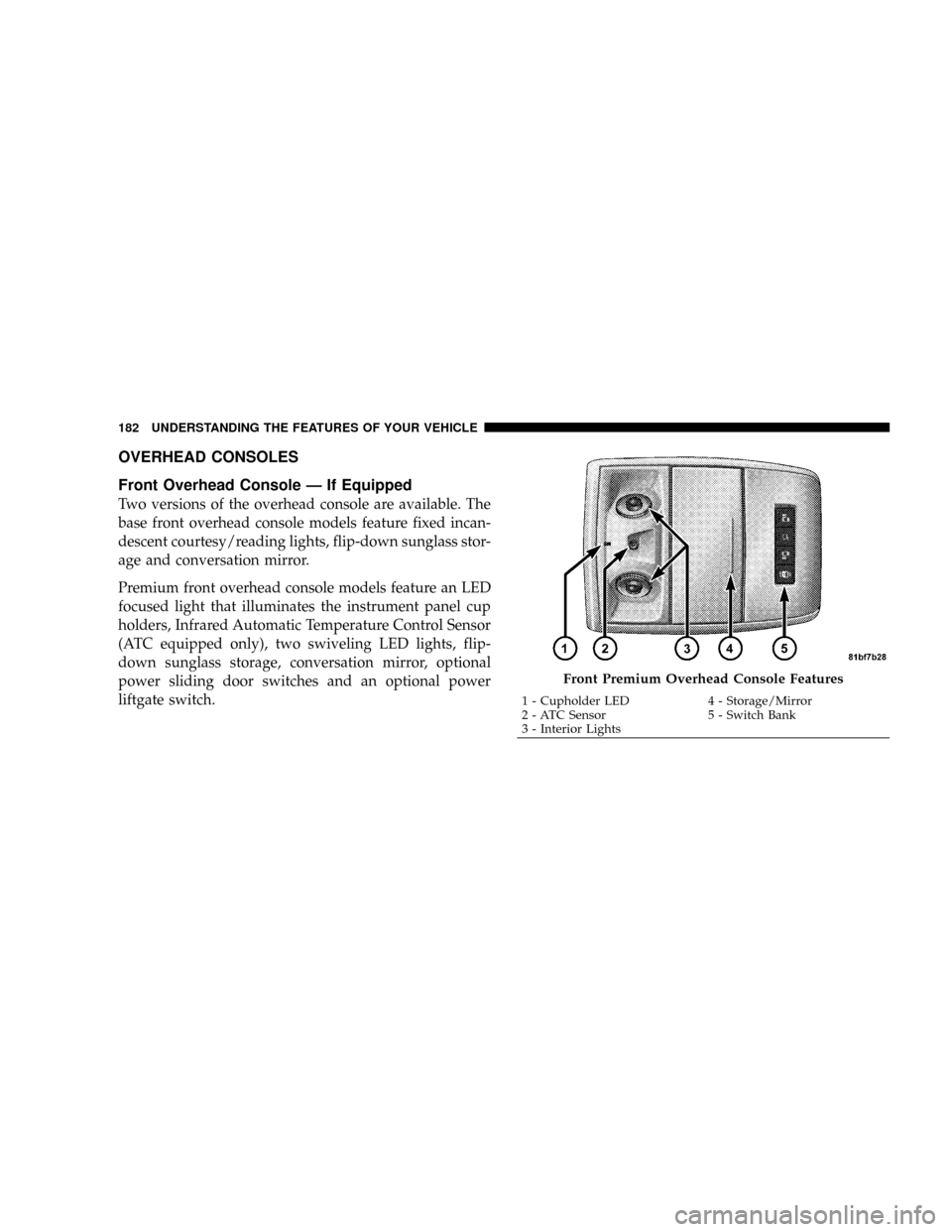
Premium front overhead console models feature an LED
focused light that illuminates the instrument panel cup
holders, Infrared Automatic Temperature Control Sensor
(ATC equipped only), two swiveling LED lights, flip-
down sunglass storage, conversation mirror, optional
power sliding door switches and an optional power
liftgate switch.
Front Premium Overhead Console Features
1 - Cupholder LED 4 - Storage/Mirror
2 - ATC Sensor 5 - Switch Bank
3 - Interior Lights 182 UNDERSTANDING THE FEATURES OF YOUR VEHICLE
Page 310 of 531
Only when the front control for the rear blower is in the
RRposition do the second seat occupants have control of
the rear blower speed.
The rear blower control, located in the rear overhead
console has an off position and a range of blower speeds.
This allows the second seat occupants to control the
volume of air circulated in the rear of the vehicle.
CAUTION!
Interior air enters the Manual Rear Zone Climate
Control system through an intake grille located in the
passenger side trim panel behind the third seat. The
heater outlets are located in the passenger side trim
panel just behind the sliding door. Do not block or
place objects directly in front of the inlet grille or
heater outlets. The electrical system could overload
causing damage to the blower motor.
Rear Temperature Control
When the blower knob on the front climate control unit is
set to any position other thanRR, the rear temperature
selection follows the setting of the rear temperature
control knob on the front climate control unit. The rear
mode selection follows the setting of the rear mode
control knob.
To change the temperature in the rear of the vehicle,
rotate the temperature control knob counterclockwise for
cold and clockwise for heated air.
When rear controls are locked by the front system, the
lock symbol on the temperature knob is illuminated and
the rear overhead adjustments are ignored.
The rear airflow modes will mirror the front unit opera-
tion. Rear PANEL mode is automatically selected when
the front control is in the PANEL mode. When the front
unit is in BI-LEVEL mode, airflow will be emitted from
both the upper and lower rear outlets. When the front
308 UNDERSTANDING YOUR INSTRUMENT PANEL
Page 322 of 531
A/C AIR FILTER Ð IF EQUIPPED
On vehicles equipped with Automatic Temperature Con-
trol (ATC), the climate control system filters out dust and
pollen from the air. Refer to Section 7 ªAir Conditioningº
for filter replacement instructions.
ELECTRIC REAR WINDOW DEFROSTER Ð IF
EQUIPPED
Press this button (located on your front climate
control) to turn on the rear window defroster and
the optional heated mirrors. A light will show that the
defroster is on. The defroster automatically turns off after
about ten minutes of operation, as long as the ignition
switch is in the ON position.
After the initial time interval has expired, if the rear
window defogger switch is pressed to the on position
again (during the same ignition cycle), the system will
automatically turn off after about five minutes.NOTE:You may turn off the heated mirror feature at
anytime by pressing the rear window defogger switch a
second time.
CAUTION!
To avoid damaging the electrical conductors of the
rear window defroster, do not use scrapers, sharp
instruments, or abrasive window cleaners on the
interior surface of the window.
Labels can be peeled off after soaking with warm
water.
320 UNDERSTANDING YOUR INSTRUMENT PANEL
Page 326 of 531
STARTING PROCEDURES
Before starting your vehicle, adjust your seat, adjust the
inside and outside mirrors, fasten your seat belt, and if
present, instruct all other occupants to buckle their seat
belts.
WARNING!
NEVER leave unattended children alone in a vehicle.
Leaving children in a vehicle is dangerous for a
number of reasons. A child or others could be seri-
ously or fatally injured. Don't leave the key in the
ignition. A child could operate power windows,
other controls, or move the vehicle.
WARNING!
DO NOT leave animals or children inside parked
vehicles in hot weather. Interior heat build-up may
cause serious injury or death.
WARNING!
Be sure to turn off the engine and remove the key
from the ignition switch if you want to rest or sleep
in your car. Accidents can be caused by inadvertently
moving the gear selection lever. Accidents can also be
caused by pressing the accelerator pedal. This may
cause excessive heat in the exhaust system, resulting
in overheating and vehicle fire, which may cause
serious or fatal injuries.
324 STARTING AND OPERATING
Page 474 of 531
2. To maintain the high gloss shine, apply a scratch and
swirl remover onto a damp cloth and apply to door
applique. Rub the applique with a firm pressure then buff
lightly with a clean cotton cloth until a high gloss shine is
achieved.
Cleaning Headlights
Your vehicle has plastic headlights that are lightweight
and less susceptible to stone breakage than glass head-
lights.
Plastic is not as scratch resistant as glass and therefore
different lens cleaning procedures must be followed.
To minimize the possibility of scratching the lenses and
reducing light output, avoid wiping with a dry cloth. To
remove road dirt, wash with a mild soap solution fol-
lowed by rinsing.
Do not use abrasive cleaning components, solvents, steel
wool or other aggressive material to clean the lenses.
Glass Surfaces
All glass surfaces should be cleaned on a regular basis
with MopartGlass Cleaner or any commercial
household-type glass cleaner. Never use an abrasive type
cleaner. Use caution when cleaning the inside rear win-
dow equipped with electric defrosters or the right rear
quarter window equipped with the radio antenna. Do
not use scrapers or other sharp instruments which may
scratch the elements.
When cleaning the rearview mirror, spray cleaner on the
towel or rag that you are using. Do not spray cleaner
directly on the mirror.
Cleaning Plastic Instrument Cluster Lenses
The lenses in front of the instruments in this vehicle are
molded in clear plastic. When cleaning the lenses, care
must be taken to avoid scratching the plastic.
472 MAINTAINING YOUR VEHICLE
Page 479 of 531
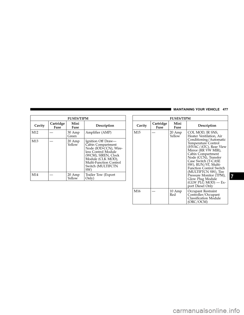
FUSES/TIPM
CavityCartridge
FuseMini
FuseDescription
M12 Ð 30 Amp
GreenAmplifier (AMP)
M13 Ð 20 Amp
YellowIgnition Off DrawÐ
Cabin Compartment
Node (IOD-CCN), Wire-
less Control Module
(WCM), SIREN, Clock
Module (CLK MOD),
Multi-Function Control
Switch (MULTIFCTN
SW)
M14 Ð 20 Amp
YellowTrailer Tow (Export
Only)FUSES/TIPM
CavityCartridge
FuseMini
FuseDescription
M15 Ð 20 Amp
YellowCOL MOD, IR SNS,
Heater Ventilation, Air
Conditioning/Automatic
Temperature Control
(HVAC/ATC), Rear View
Mirror (RR VW MIR),
Cabin Compartment
Node (CCN), Transfer
Case Switch (T-CASE
SW), RUN/ST, Multi-
Function Control Switch
(MULTIFTCN SW), Tire
Pressure Monitor (TPM),
Glow Plug Module
(GLW PLG MOD) Ð Ex-
port Diesel Only
M16 Ð 10 Amp
RedOccupant Restraint
Controller/Occupant
Classification Module
(ORC/OCM)
MAINTAINING YOUR VEHICLE 477
7
Page 480 of 531
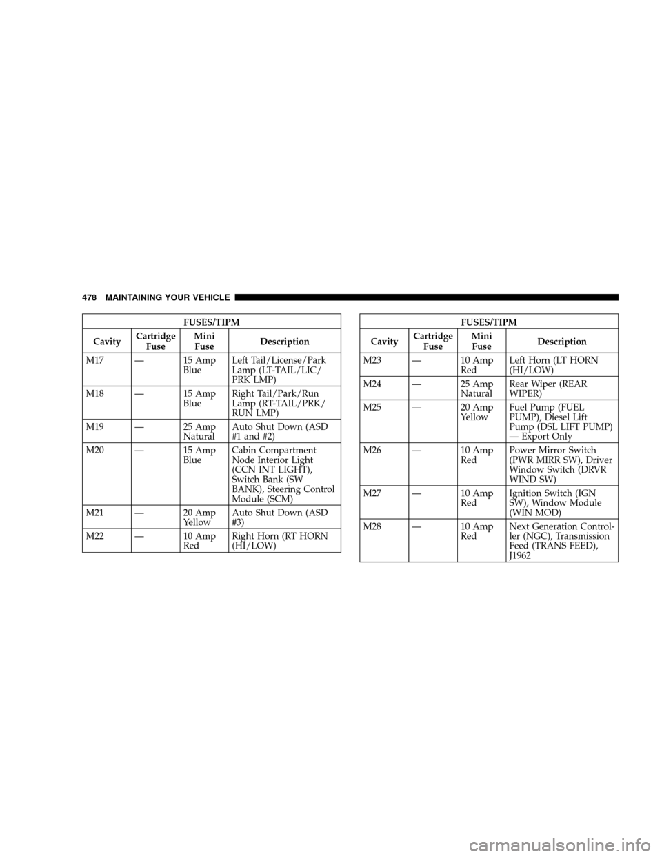
FUSES/TIPM
CavityCartridge
FuseMini
FuseDescription
M17 Ð 15 Amp
BlueLeft Tail/License/Park
Lamp (LT-TAIL/LIC/
PRK LMP)
M18 Ð 15 Amp
BlueRight Tail/Park/Run
Lamp (RT-TAIL/PRK/
RUN LMP)
M19 Ð 25 Amp
NaturalAuto Shut Down (ASD
#1 and #2)
M20 Ð 15 Amp
BlueCabin Compartment
Node Interior Light
(CCN INT LIGHT),
Switch Bank (SW
BANK), Steering Control
Module (SCM)
M21 Ð 20 Amp
YellowAuto Shut Down (ASD
#3)
M22 Ð 10 Amp
RedRight Horn (RT HORN
(HI/LOW)FUSES/TIPM
CavityCartridge
FuseMini
FuseDescription
M23 Ð 10 Amp
RedLeft Horn (LT HORN
(HI/LOW)
M24 Ð 25 Amp
NaturalRear Wiper (REAR
WIPER)
M25 Ð 20 Amp
YellowFuel Pump (FUEL
PUMP), Diesel Lift
Pump (DSL LIFT PUMP)
Ð Export Only
M26 Ð 10 Amp
RedPower Mirror Switch
(PWR MIRR SW), Driver
Window Switch (DRVR
WIND SW)
M27 Ð 10 Amp
RedIgnition Switch (IGN
SW), Window Module
(WIN MOD)
M28 Ð 10 Amp
RedNext Generation Control-
ler (NGC), Transmission
Feed (TRANS FEED),
J1962
478 MAINTAINING YOUR VEHICLE