lock DODGE GRAND CARAVAN 2011 5.G Owner's Manual
[x] Cancel search | Manufacturer: DODGE, Model Year: 2011, Model line: GRAND CARAVAN, Model: DODGE GRAND CARAVAN 2011 5.GPages: 100, PDF Size: 4.02 MB
Page 37 of 100
NOTE:Your radio may not be equipped with the Uconnect™ Voice Command and
Uconnect™ Phone features. To determine if your radio has these features, press the
Voice Command button on the radio. You will hear a voice prompt if you have the
feature, or see a message on the radio stating “Uconnect Phone not available” if you do
not.
• Your radio has many features that add to the comfort and convenience of you andyour passengers. Some of these radio features should not be used when driving
because they take your eyes from the road or your attention from driving.
• The radio sales code is located on the lower right side of the radio faceplate.
Seek Up/Down Buttons
• Press to seek through radio stations in AM, FM, or SAT bands. Seek through tracks in CD mode.
• Hold either button to bypass stations without stopping.
Audio Settings
• Press the TUNE/SCROLL control knob and BASS, MID, TREBLE, BALANCE and FADE will display. Rotate the TUNE/SCROLL control knob to select the desired
setting.
Audio Jack
• The Audio Jack allows a portable device, such as an MP3 player or a cassetteplayer, to be plugged into the radio and utilize the vehicle’s audio system, using a
3.5 mm audio cable to amplify the source and play through the vehicle speakers.
• Pressing the AUX button will change the mode to auxiliary device if the Audio Jack is connected, allowing the music from your portable device to play through the
vehicle's speakers.
• The functions of the portable device are controlled using the device buttons. The volume may be controlled using the radio or portable device.
Clock Setting
• Press and hold the TIME button until the hours blink; turn the TUNE/SCROLLcontrol knob to set the hours.
• Press the TUNE/SCROLL control knob until the minutes begin to blink; turn the TUNE/SCROLL control knob to set the minutes.
• Press the TUNE/SCROLL control knob to save the time change.
• To exit, press any button/knob or wait five seconds.
Store Radio Presets
• Press the SET/RND button once and SET 1 will show in the display. Then select button (1–6).
• A second station may be added to each push button. Press the SET/RND button twice and SET 2 will show in the display, then select button (1–6).
ELECTRONICS
35
Page 39 of 100
NOTE:Your radio may not be equipped with the Uconnect™ Voice Command and
Uconnect™ Phone features. To determine if your radio has these features, press the
Voice Command button on the radio. You will hear a voice prompt if you have the
feature, or see a message on the radio stating “Uconnect Phone not available” if you do
not.
• Your radio has many features that add to the comfort and convenience of you andyour passengers. Some of these radio features should not be used when driving
because they take your eyes from the road or your attention from driving.
• The radio sales code is located on the lower right side of the radio faceplate.
Seek Up/Down
• Media Center 730N: Press the SEEK hard-key to seek through radio stations in AM, FM, or SAT bands. Seek through tracks in CD or iPod®modes or through
songs in the HDD playlist.
• Media Center 430/430N: Press the SEEK up/down arrow soft-keys to change the currently playing station in AM, FM or SAT bands. Seek through tracks in CD or
iPod
®modes or through songs in the HDD playlist.
Audio Jack
• The Audio Jack allows a portable device, such as an MP3 player or a cassetteplayer, to be plugged into the radio and utilize the vehicle’s audio system, using a
3.5 mm audio cable, to amplify the source and play through the vehicle speakers.
• Pressing the AUX button will change the mode to auxiliary device if the Audio Jack is connected, allowing the music from your portable device to be heard through the
vehicle's speakers.
• The functions of the portable device are controlled using the device buttons. The volume may be controlled using the radio or portable device.
Clock Setting
• Turn the radio on, then touch the screen where the time is displayed.
• Touch the USER CLOCK soft-key (Navigation radio only).
• To adjust the hours, touch either the HOUR FORWARD or HOUR BACKWARDsoft-key.
• To adjust the minutes, touch either the MINUTE FORWARD or MINUTE BACKWARD soft-key.
• To save the new time setting, touch the screen where the word “Save” is displayed.
Store Radio Presets
• Media Center 730N: Press the RADIO/MEDIA hard-key until AM FM SAT is displayed in the upper left corner of the screen.
• Media Center 430/430N: Press the RADIO hard-key to display AM FM SAT in the upper left corner of the screen.
• Select the radio band by touching either the AM, FM, or SAT soft-key.
• Find the station to store by either pressing the SEEK UP/DOWN hard-keys (Media Center 730N), touching the right and left arrow soft-keys (Media Center
430/430N), touching the SCAN soft-key, or by using the DIRECT TUNE soft-key.
ELECTRONICS
37
Page 51 of 100
PROGRAMMABLE FEATURES
Electronic Vehicle Information Center (EVIC) – If Equipped
• The EVIC can be used to program the following Personal Settings. Press andrelease the MENU button until Personal Settings displays, then press the DOWN
button
to scroll through the settings. Press the SELECT buttonto
change the setting.
• Language • Turn Headlamps On With Remote Key
Unlock
• Lock Door Automatically at 15 mph (24 km/h) • Confirmation of Voice Commands
• Auto Unlock On Exit • Illuminated Approach
• Remote Unlock Driver's Door 1st • Hill Start Assist (HSA)
• Sound Horn With Remote Key Lock • Display Units In
• Flash Lights With Remote Key Lock • Automatic Compass Calibration
• Delay Turning Headlights Off • Compass Variance
• Delay Power Off to Accessories until Exit • To Set the Variance
Key Fob Programmable Features
• The following features may also be programmed by using the Key Fob transmitter
or the ignition switch and driver's door lock switch.
NOTE: Pressing the LOCK button while you are inside the vehicle will activate the
Vehicle Security Alarm. Opening a door with the Vehicle Security Alarm activated will
cause the alarm to sound. Press the UNLOCK button to deactivate the Vehicle Security
Alarm.
Unlock On First Press• To unlock either the driver's side, or all doors, on the first press of the UNLOCK button:
• Press and hold the LOCK button for at least 4 seconds, but no longer than
10 seconds. Then, press and hold the UNLOCK button while still holding the
LOCK button.
• Release both buttons at the same time.
ELECTRONICS
49
Page 52 of 100
Auto Unlock Doors On Exit• To have all of the vehicle doors unlock when any door is opened: • Enter your vehicle and close all the doors.
• Cycle the ignition switch between LOCK and ON and then back to LOCK fourtimes, ending up in the LOCK position (do not start the engine).
• Press the power door UNLOCK switch to unlock the doors. A single chime will indicate that programming is complete.
Auto Door Lock • To have the doors lock automatically when the vehicle’s speed exceeds 15 mph (24 km/h):
• Enter your vehicle and close all the doors.
• Cycle the ignition switch between LOCK and ON and then back to LOCK four
times, ending up in the LOCK position (do not start the engine).
• Press the power door LOCK switch to lock the doors. A single chime will indicate that programming is complete.
Sound Horn With Lock • To turn the horn chirp on or off when the doors are locked: • Press the LOCK button for at least 4 seconds, but no longer than 10 seconds.Then, press the PANIC button while still holding the LOCK button.
• Release both buttons at the same time.
Flashing Lights With Lock • The turn signal lights flashing, when the doors are locked or unlocked, feature can be turned on or off. To turn this feature on or off:
• Press and hold the UNLOCK button for at least 4 seconds, but no longer than
10 seconds. Then, press and hold the LOCK button while still holding the
UNLOCK button.
• Release both buttons at the same time.
ELECTRONICS
50
Page 57 of 100
IN-FLOOR STORAGE –
STOW 'N GO®
Second Row Seat Storage Bins
• Storage bins are located in the floorin front of the second row seats that
can be used when the second row
seat is in the upright position. Pull
up on the storage bin latch to open
the cover. Slide the storage bin
locking mechanism to the "Lock"
position to allow greater access to
the storage bin.
Cargo Area Storage
• The liftgate sill plate has a raisedline with the statement “Load To
This Line”. This line indicates how
far rearward cargo can be placed
without interfering with liftgate
closing.
WARNING!
In a collision, serious injury could
result if the seat storage bin covers
are not properly latched. Do not
drive the vehicle with the storage bin
covers open. Keep the storage bin
covers closed and latched while the
vehicle is in motion. Do not use a
storage bin latch as a tie down.
ROOF LUGGAGE RACK
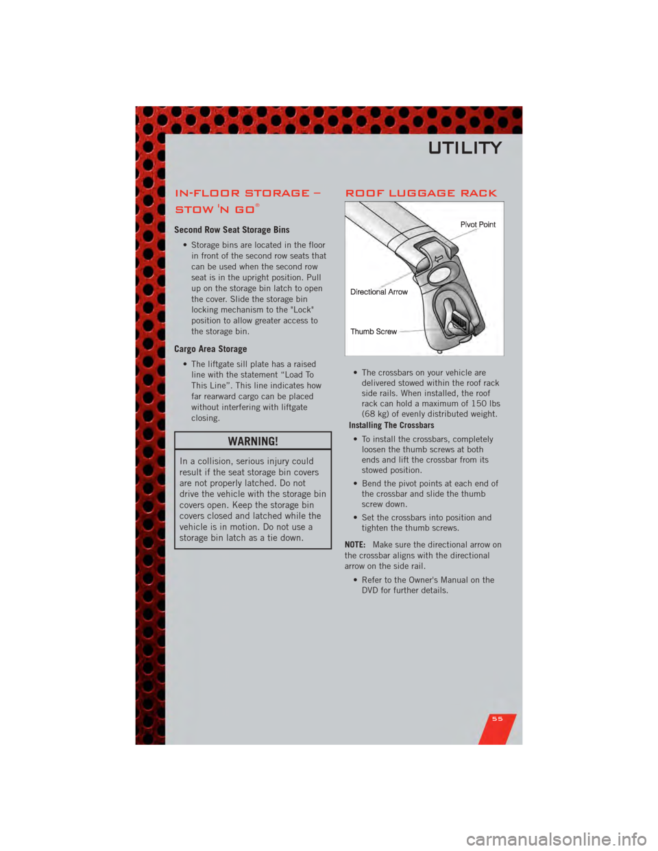
• The crossbars on your vehicle aredelivered stowed within the roof rack
side rails. When installed, the roof
rack can hold a maximum of 150 lbs
(68 kg) of evenly distributed weight.
Installing The Crossbars
• To install the crossbars, completely loosen the thumb screws at both
ends and lift the crossbar from its
stowed position.
• Bend the pivot points at each end of the crossbar and slide the thumb
screw down.
• Set the crossbars into position and tighten the thumb screws.
NOTE: Make sure the directional arrow on
the crossbar aligns with the directional
arrow on the side rail.
• Refer to the Owner's Manual on theDVD for further details.
UTILITY
55
Page 61 of 100
• Your vehicle has also been equipped with a TPMS malfunction indicator to indicatewhen the system is not operating properly. The TPMS malfunction indicator is
combined with the low tire pressure telltale. When the system detects a
malfunction, the telltale will flash for approximately one minute and then remain
continuously illuminated. This sequence will continue each time the vehicle is
restarted as long as the malfunction exists.
• When the malfunction indicator is illuminated, the system may not be able to detect or signal low tire pressure as intended. TPMS malfunctions may occur for a
variety of reasons, including the installation of replacement or alternate tires or
wheels on the vehicle that prevent the TPMS from functioning properly. Always
check the TPMS malfunction telltale after replacing one or more tires or wheels on
your vehicle, to ensure that the replacement or alternate tires and wheels allow the
TPMS to continue to function properly.
CAUTION!
The TPMS has been optimized for the original equipment tires and wheels.
TPMS pressures and warning have been established for the tire size equipped
on your vehicle. Undesirable system operation or sensor damage may result
when using replacement equipment that is not of the same size, type, and/or
style. Aftermarket wheels can cause sensor damage. Do not use tire sealant
from a can, or balance beads if your vehicle is equipped with a TPMS, as
damage to the sensors may result.
- Engine Temperature Warning Light
• This light warns of an overheated engine condition.
• If the light turns on or flashes continuously while driving, safely pull over and stopthe vehicle. If the A/C system is on, turn it off. Also, shift the transmission into
NEUTRAL and idle the vehicle. If the temperature reading does not return to
normal, turn the engine off immediately and call for service.
• We recommend that you do not operate the vehicle or engine damage will occur. Have the vehicle serviced immediately.
WARNING!
A hot engine cooling system is dangerous. You or others could be badly burned
by steam or boiling coolant. You may want to call an authorized service center
for service if your vehicle overheats.
BRAKE- Brake Warning Light
• The Brake Warning light illuminates when there is either a system malfunction orthe parking brake is applied. If the light is on and the parking brake is not applied,
it indicates a possible brake hydraulic malfunction, brake booster problem or an
Anti-Lock Brake System problem.
• We recommend you drive to the nearest service center and have the vehicle serviced immediately.
WHAT TO DO IN EMERGENCIES
59
Page 62 of 100
WARNING!
Driving a vehicle with the red brake light on is dangerous. Part of the brake
system may have failed. It will take longer to stop the vehicle. You could have a
collision. Have the vehicle checked immediately.
- Malfunction Indicator Light (MIL)
• Certain conditions, such as a loose or missing gas cap, poor fuel quality, etc., mayilluminate the MIL after engine start. The vehicle should be serviced if the light
stays on through several typical driving cycles. In most situations, the vehicle will
drive normally and not require towing.
• If the MIL flashes when the engine is running, serious conditions may exist that could lead to immediate loss of power or severe catalytic converter damage. We
recommend you do not operate the vehicle. Have the vehicle serviced immediately.
- Electronic Stability Control (ESC) Indicator Light/Brake Assist System (BAS)
Warning Light
• If the ESC/BAS warning light comes on continuously with the engine running, a malfunction has been detected.
• If this light remains on after several ignition cycles, and the vehicle has been driven several miles (kilometers) at speeds greater than 30 mph (48 km/h), we
recommend you drive to the nearest service center and have the vehicle serviced
immediately.
- Charging System Light
• This light shows the status of the electrical charging system. If the chargingsystem light remains on, it means that the vehicle is experiencing a problem with
the charging system.
• We recommend you do not continue driving if the charging system light is on. Have the vehicle serviced immediately.
- Oil Pressure Warning Light
• This light indicates low engine oil pressure. If the light turns on while driving, stopthe vehicle and shut off the engine as soon as possible. A chime will sound for four
minutes when this light turns on.
• We recommend you do not operate the vehicle or engine damage will occur. Have the vehicle serviced immediately.
- Anti-Lock Brake (ABS) Light
• This light monitors the Anti-Lock Brake System (ABS).
• If the light is not on during starting, stays on, or turns on while driving, werecommend you drive to the nearest service center and have the vehicle serviced
immediately.
WHAT TO DO IN EMERGENCIES
60
Page 63 of 100
- Electronic Throttle Control (ETC) Light
• This light informs you of a problem with the Electronic Throttle Control (ETC)system.
• If a problem is detected, the light will come on while the engine is running. Cycle the ignition when the vehicle has completely stopped and the shift lever is placed
in the PARK position; the light should turn off.
• If the light remains lit with the engine running, your vehicle will usually be drivable; however, see an authorized service center immediately. If the light is
flashing when the engine is running, immediate service is required and you may
experience reduced performance, an elevated/rough idle or engine stall and your
vehicle may require towing.
- Air Bag Warning Light
• If the light is not on during starting, stays on, or turns on while driving, have thevehicle serviced by an authorized service center immediately.
Fuel Cap/Loose Gas Cap Message
• If a “gas cap” message (shown as gASCAP) appears, tighten the gas cap until a“clicking” sound is heard.
• Press the odometer reset button to turn the message off.
• If the message continues to appear for more than three days after tightening the gas cap, see your authorized service center.
Oil Change Indicator
Message
• If an “oil change” message (shown as CHAngE OIL) appears and a single chime sounds, it is time for your next required oil change.
Resetting The Light After Servicing
• Turn the ignition switch to the ON/RUN position (do not start engine).
• Fully depress the accelerator pedal three times within 10 seconds.
• Turn the ignition switch to the OFF/LOCK position.
WHAT TO DO IN EMERGENCIES
61
Page 68 of 100
Preparations For Jacking
1. Park the vehicle on a firm, level surface. Avoid ice or slippery areas.
2. Turn on the Hazard Warning flasher.
3. Set the parking brake.
4. Place the shift lever into PARK.
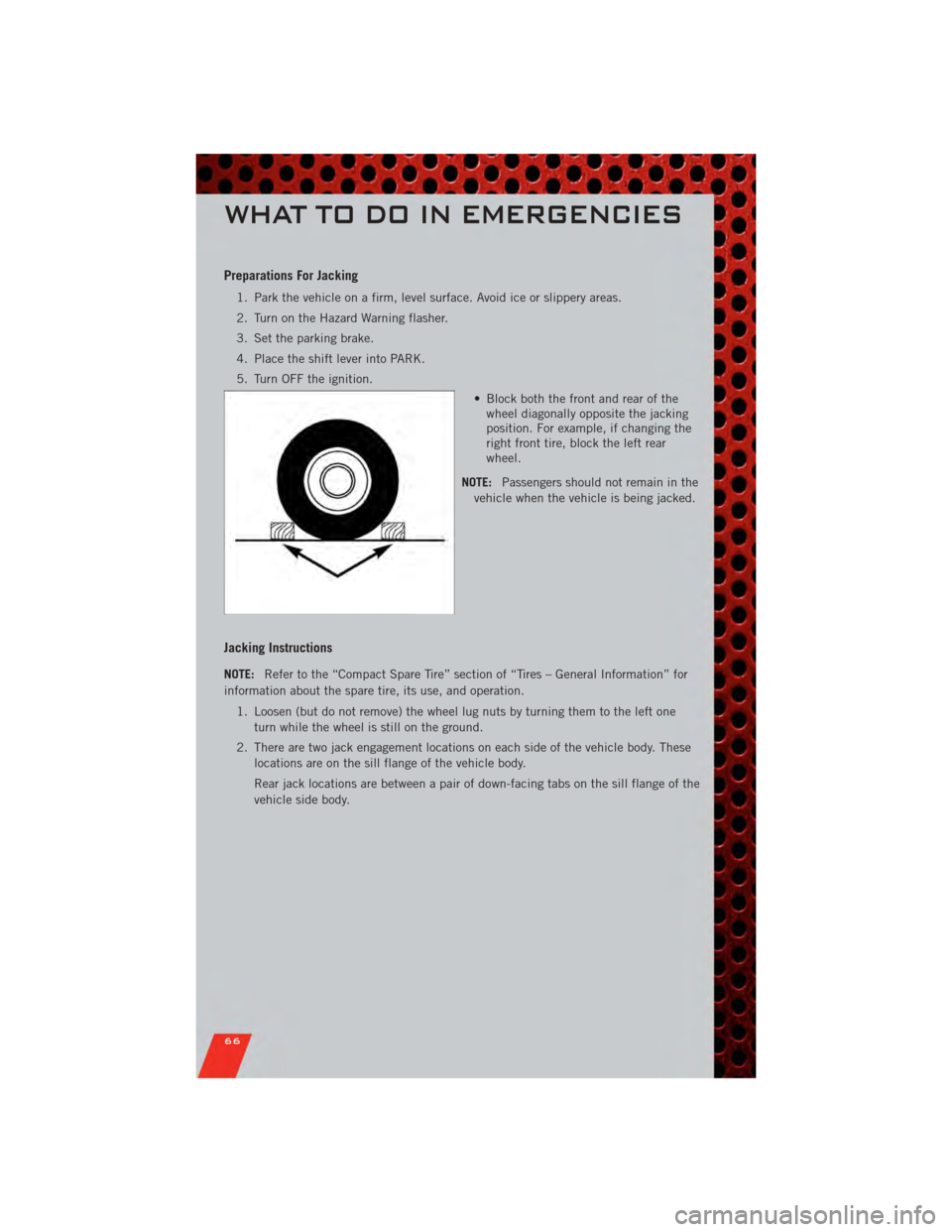
5. Turn OFF the ignition.• Block both the front and rear of thewheel diagonally opposite the jacking
position. For example, if changing the
right front tire, block the left rear
wheel.
NOTE: Passengers should not remain in the
vehicle when the vehicle is being jacked.
Jacking Instructions
NOTE: Refer to the “Compact Spare Tire” section of “Tires – General Information” for
information about the spare tire, its use, and operation.
1. Loosen (but do not remove) the wheel lug nuts by turning them to the left one turn while the wheel is still on the ground.
2. There are two jack engagement locations on each side of the vehicle body. These locations are on the sill flange of the vehicle body.
Rear jack locations are between a pair of down-facing tabs on the sill flange of the
vehicle side body.
WHAT TO DO IN EMERGENCIES
66
Page 70 of 100
11. Stow the cable and wheel spacer before driving the vehicle. Reassemble thewinch handle extensions to form a “T” and fit the winch T-handle over the drive
nut. Rotate the nut to the right until the winch mechanism clicks at least three
times.
12. Stow the jack, jack handle and winch handle tools back in the stowage compartment.
13. Check the compact spare tire pressure as soon as possible. Correct the tire pressure, as required.
Securing The Spare Tire
1. Assemble the winch handle extensions to form a T-handle and fit the winchT-handle over the drive nut. Rotate the nut to the left until the winch mechanism
stops turning freely. This will allow enough slack in the cable to allow you to pull
the wheel spacer out from under the vehicle.
2. Assemble the winch handle extensions to form the spare tire hook, and pull the wheel spacer from under the vehicle.
3. Turn the compact spare tire so that the valve stem is down, and place the tire into the spare tire/cover assembly. Slide the wheel spacer through the center of the
wheel and spare tire/cover assembly, so that the two retainer tabs snap out and
engage the spare tire cover on the opposite side.
4. Using the winch T-handle, rotate the drive nut to the right until the compact spare tire/cover assembly is drawn into place against the underside of the vehicle.
5. Continue to rotate the nut to the right until you hear the winch mechanism click three times. It cannot be overtightened. Check under the vehicle to ensure the
compact spare tire/cover assembly is positioned correctly against the underside of
the vehicle.
Road Tire Installation
Vehicles Equipped With Wheel Covers
1. Mount the road tire on the axle.
2. To ease the installation process for steel wheels with wheel covers, install two lug nuts on the mounting studs which are on each side of the valve stem. Install the
lug nuts with the cone shaped end of the nut toward the wheel. Lightly tighten
the lug nuts.
3. Align the valve notch in the wheel cover with the valve stem on the wheel. Install the cover by hand, snapping the cover over the two lug nuts. Do not use a hammer
or excessive force to install the cover.
4. Install the remaining lug nuts with the cone shaped end of the nut toward the wheel. Lightly tighten the lug nuts. To avoid the risk of forcing the vehicle off the
jack, do not tighten the lug nuts fully until the vehicle is lowered to the ground.
5. Lower the vehicle to the ground by turning the jack handle counterclockwise.
6. Finish tightening the lug nuts. Push down on the wrench while at the end of the handle for increased leverage. Tighten the lug nuts in a star pattern until each nut
has been tightened twice. The correct tightness of each lug nut is 102 ft/lbs
(138 N·m). If in doubt about the correct tightness, have them checked with a
torque wrench by your authorized dealer or service station.
WHAT TO DO IN EMERGENCIES
68