ECU DODGE GRAND CARAVAN 2013 5.G User Guide
[x] Cancel search | Manufacturer: DODGE, Model Year: 2013, Model line: GRAND CARAVAN, Model: DODGE GRAND CARAVAN 2013 5.GPages: 132, PDF Size: 4.51 MB
Page 9 of 132
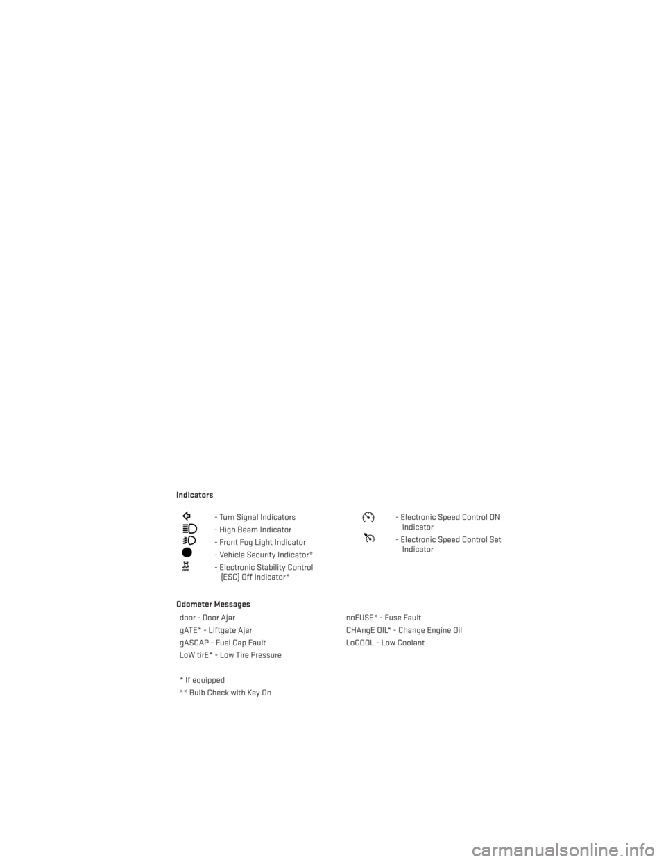
Indicators
- Turn Signal Indicators
- High Beam Indicator
- Front Fog Light Indicator
- Vehicle Security Indicator*
- Electronic Stability Control(ESC) Off Indicator*
- Electronic Speed Control ONIndicator
- Electronic Speed Control SetIndicator
Odometer Messages door - Door Ajar noFUSE* - Fuse Fault
gATE* - Liftgate Ajar CHAngE OIL* - Change Engine Oil
gASCAP - Fuel Cap Fault LoCOOL - Low Coolant
LoW tirE* - Low Tire Pressure
* If equipped
** Bulb Check with Key On
CONTROLS AT A GLANCE
7
Page 11 of 132
WARNING!
• Never leave children alone in a vehicle, or with access to an unlocked vehicle.Allowing children to be in a vehicle unattended is dangerous for a number of reasons.
A child or others could be severely injured or killed. Children should be warned not to
touch the parking brake, brake pedal, or the shift lever. Do not leave the Key Fob inside
the vehicle, or in a location accessible to children. A child could start the vehicle,
operate power windows, other controls, or move the vehicle.
• Do not leave children or animals inside parked vehicles in hot weather. Interior heat
build-up may cause them to be severely injured or killed.
• Keep Key Fob transmitters away from children. Operation of the Remote Start
System, windows, door locks or other controls could cause serious injury or death.
REMOTE START
• Press the REMOTE START buttonx2on the Key Fob twice within five seconds. Pressing
the REMOTE START button a third time shuts the engine off.
• To drive the vehicle, press the UNLOCK button, insert the Key Fob in the ignition and turn to the ON/RUN position.
• With remote start, the engine will only run for 15 minutes (timeout) unless the ignition Key Fob is placed in the ON/RUN position.
• The vehicle must be started with the Key Fob after two consecutive timeouts.
WARNING!
• Do not start or run an engine in a closed garage or confined area. Exhaust gas contains Carbon Monoxide (CO) which is odorless and colorless. Carbon Monoxide is
poisonous and can cause you or others to be severely injured or killed when inhaled.
• Keep Key Fob transmitters away from children. Operation of the Remote Start
System, windows, door locks or other controls could cause you and others to be
severely injured or killed.
THEFT ALARM
To Arm:
• Press the Key Fob LOCK button or the power door lock switch while the door is open.
To Disarm:
• Press the Key Fob UNLOCK button or turn the ignition to the ON/RUN position.
GETTING STARTED
9
Page 13 of 132
• This vehicle is equipped with Supplemental Seat-Mounted Side Air Bags to provideenhanced protection to help protect an occupant during a side impact.
• This vehicle is equipped with a Supplemental Driver Side Knee Air Bag to provide enhanced protection and work together with the Driver Advanced Front Air Bag during a
frontal impact.
• If the Air Bag Warning Light
is not on during starting, stays on, or turns on while
driving, have the vehicle serviced by an authorized service center immediately.
• Refer to the Owner's Manual on the DVD for further details regarding the Supplemental Restraint System (SRS).
WARNING!
• Relying on the air bags alone could lead to more severe injuries in a collision. The air
bags work with your seat belt to restrain you properly. In some collisions, the air bags
won't deploy at all. Always wear your seat belts even though you have air bags.
• Being too close to the steering wheel or instrument panel during Advanced Front Air
Bag deployment could cause serious injury, including death. Air bags need room to
inflate. Sit back, comfortably extending your arms to reach the steering wheel or
instrument panel.
• Supplemental Side Air Bag Inflatable Curtains and Supplemental Seat-Mounted Side
Air Bags need room to inflate. Do not lean against the door or window. Sit upright in
the center of the seat.
• Being too close to the Supplemental Side Air Bag Inflatable Curtain and/or Seat-
Mounted Side Air Bag during deployment could cause you to be severely injured or
killed.
• Do not drive your vehicle after the air bags have deployed. If you are involved in
another collision, the air bags will not be in place to protect you.
• After any collision, the vehicle should be taken to an authorized dealer immediately.
CHILD RESTRAINTS
• Children 12 years and under should ride properly buckled up in a rear seat, if available. According to crash statistics, children are safer when properly restrained in the rear
seats rather than in the front.
• Every state in the United States and all Canadian provinces require that small children ride in proper restraint systems. This is the law, and you can be prosecuted for ignoring it.
NOTE:
• For additional information, refer to www.seatcheck.org or call 1–866–SEAT-CHECK (1–866–732–8243).
• Canadian residents, should refer to Transport Canada’s website for additional informa- tion http://www.tc.gc.ca/eng/roadsafety/safedrivers-childsafety-index-53.htm.
GETTING STARTED
11
Page 14 of 132
Installing The LATCH - Compatible Child Restraint System
•
Each vehicle, except commercial cargo vehicles, is equipped with the child restraint anchor-
age system called LATCH, which stands for Lower Anchors and Tether for CHildren.
• Two LATCH child restraint anchorage systems are installed on all second-row seats and in the center position on all third row fold-in-floor seats.
• Second-row seats also feature tether strap anchorages, located in the rear surface of the seatback.
• In addition, all third row fold-in-floor seats are equipped with a child restraint tether anchor at the center seating position.
Installing The Lower Attachments:
• The vehicle lower anchorages are round bars located at the rear of the seat cushion where it meets the seatback.
• Loosen the child seat adjusters on the lower child restraint attachment straps to
ease the installation.
NOTE:
It is recommended to loosen the top tether
strap and route it loosely prior to securing
the lower anchors so the top tether strap is
not trapped between the vehicle seat and
child restraint.
• Attach the lower child restraint attach- ment straps to the vehicle’s lower anchor
bars. Ensure that the lower attachment strap is firmly engaged and that the hook is
secure.
• Tighten the lower attachment strap while firmly pushing the child restraint rearward and downward into the vehicle seat. Remove all slack in the lower attachment straps.
Installing The Top Tether Strap (With Either Lower Anchors Or Vehicle Seat Belt):
• Route the top tether strap under the adjustable head restraint between the steel posts.
• Provide enough slack for the tether strap to reach the tether anchor located near
the bottom of the seat back.
• Clip tether hook to tether anchor. Ensure that the hook is firmly engaged and se-
cure.
• Remove all slack and tighten tether strap according to child restraint manufactur-
er’s instructions.
NOTE:
The top tether strap is always to be secured,
regardless of if the child restraint is installed with the lower anchors or the vehicle seat belt.
GETTING STARTED
12
Page 15 of 132
Installing The Child Restraint Using The Vehicle Seat Belts
• To install a child restraint, first, pull enough of the seat belt webbing from the retractor toroute it through the belt path of the child restraint and slide the latch plate into the
buckle.
• Next, extract all the seat belt webbing out of the retractor and then allow the belt to retract into the retractor. Finally, pull on any excess webbing to tighten the lap portion
around the child restraint. Any seat belt system will loosen with time, so check the belt
occasionally, and pull it tight if necessary.
• Once you have completed securing the child restraint with the seat belt, secure the top tether strap.
WARNING!
• In a collision, an unrestrained child, even a tiny baby, can become a projectile inside
the vehicle. The force required to hold even an infant on your lap could become so
great that you could not hold the child, no matter how strong you are. The child and
others could be severely injured or killed. Any child riding in your vehicle should be in
a proper restraint for the child's size.
• Failure to comply with the following conditions could result in you and others being
severely injured or killed:
• Be certain that the seat cushion is locked securely into position before usingthe seat. An improperly latched seat cushion could cause passengers to be
severely injured or killed.
• An incorrectly anchored tether strap could lead to increased head motion and
possible injury to the child. Use only the anchor positions directly behind the child
seat to secure a child restraint top tether strap.
• Rearward-facing child seats must never be used in the front seat of a vehicle with a
front passenger air bag. An air bag deployment could cause severe injury or death to
infants in this position.
GETTING STARTED
13
Page 35 of 132
Pinch Protection Feature
• This feature will detect an obstruction in the opening of the sunroof during Express Closeoperation. If an obstruction in the path of the sunroof is detected, the sunroof will
automatically retract. Remove the obstruction if this occurs. Next, press the switch
forward and release to Express Close.
NOTE:
If three consecutive sunroof close attempts result in Pinch Protect reversals, the fourth
close attempt will be a Manual Close movement with Pinch Protect disabled.
WARNING!
• Never leave children unattended in a vehicle, and do not leave the key in the ignition switch (or leave the ignition of a vehicle equipped with Keyless Enter-N-Go™ in the
ACC or ON/Run position). Occupants, particularly unattended children, can become
entrapped by the power sunroof while operating the power sunroof switch. Such
entrapment may result in serious injury or death.
• In a collision, there is a greater risk of being thrown from a vehicle with an open
sunroof. You could also be severely injured or killed. Always fasten your seat belt
properly and make sure all passengers are properly secured.
• Do not allow small children to operate the sunroof. Never allow your fingers, other
body parts, or any object to project through the sunroof opening. Injury may result.
WIND BUFFETING
• Wind buffeting can be described as a helicopter-type percussion sound. If buffetingoccurs with the rear windows open, adjust the front and rear windows together.
• If buffeting occurs with the sunroof open, adjust the sunroof opening, or adjust any window. This will minimize buffeting.
OPERATING YOUR VEHICLE
33
Page 74 of 132
PROGRAMMABLE FEATURES
Electronic Vehicle Information Center (EVIC) – If Equipped
• The EVIC can be used to program the following Personal Settings. Press and releasethe MENU button until Personal Settings displays, then press the DOWN button
to
scroll through the settings. Press the SELECT button
to change the setting.
• Language • Intermittent Wiper Option
• Nav-Turn By Turn • Rain Sensing Wipers
•
Enable/Disable the Rear Park Assist System• Key-Off Power Delay
• Auto Unlock Doors • Illuminated Approach
• Remote Unlock Sequence • Flashers with Sliding Door
• RKE Linked To Memory • Hill Start Assist (HSA)
• Remote Start Comfort Sys. • Keyless Enter-N-Go™ (Passive Entry)
• Horn With Remote Lock • Easy Exit Seat
• Horn With Remote Start • Tilt Mirror In Reverse
• Flash Lamps With Lock • Blind Spot Alert
• Automatic High Beams • Calibrate Compass
• Headlamp Off Delay • Compass Variance
• Headlamps with Wipers (Available with Auto Headlights Only) • Turn Menu Off
Key Fob Programmable Features
• The following features may also be programmed by using the Key Fob transmitter or the
ignition switch and driver's door lock switch.
NOTE:
Pressing the LOCK button while you are inside the vehicle will activate the Vehicle Security
Alarm. Opening a door with the Vehicle Security Alarm activated will cause the alarm to
sound. Press the UNLOCK button to deactivate the Vehicle Security Alarm.
Unlock On First Press
• To unlock either the driver's side, or all doors, on the first press of the UNLOCK button: •
Press and hold the LOCK button for at least four seconds, but no longer than 10 seconds.
Then, press and hold the UNLOCK button while still holding the LOCK button.
• Release both buttons at the same time.
Auto Unlock Doors On Exit
• To have all of the vehicle doors unlock when any door is opened:• Enter your vehicle and close all the doors, and fasten your seat belt.
• Cycle the ignition switch between the LOCK and ON position four times, ending in the
LOCK position (do not start the engine).
• Press the power door UNLOCK switch to unlock the doors. A single chime will indicate that programming is complete.
ELECTRONICS
72
Page 75 of 132
Sound Horn With Lock
• To turn the horn chirp on or off when the doors are locked:• Press the LOCK button for at least four seconds, but no longer than 10 seconds. Then,
press the PANIC button while still holding the LOCK button.
• Release both buttons at the same time.
Flashing Lights With Lock
• The turn signal lights flashing, when the doors are locked or unlocked, feature can be turned on or off. To turn this feature on or off:•
Press and hold the UNLOCK button for at least four seconds, but no longer than 10 sec-
onds. Then, press and hold the LOCK button while still holding the UNLOCK button.
• Release both buttons at the same time.
UNIVERSAL GARAGE DOOR OPENER (HomeLink®)
•HomeLink® replaces up to three hand-held transmitters that operate devices such as
garage door openers, motorized gates, lighting or home security systems. The HomeLink®
unit is powered by your vehicles 12 Volt battery.
• The HomeLink® buttons that are located in the overhead console or sunvisor designate the three different HomeLink® channels.
• The HomeLink® indicator is located above the center button.
Before You Begin Programming HomeLink®
• Ensure that your vehicle is parked outside of the garage before you begin program-
ming.
• For efficient programming and accurate transmission of the radio-frequency sig-
nal, it is recommended that a new battery
be placed in the hand-held transmitter of
the device that is being programmed to
the HomeLink® system.
• Erase all channels before you begin pro- gramming. To erase the channels, place the ignition switch into the ON/RUN position,
then press and hold the two outside HomeLink® buttons (I and III) for up to 20 seconds or
until the red indicator flashes.
NOTE:
Erasing all channels should only be performed when programming HomeLink® for the first
time. Do not erase channels when programming additional buttons.
• If you have any problems, or require assistance, please call toll-free 1–800–355–3515 or, on the Internet at www.HomeLink.com for information or assistance.
ELECTRONICS
73
Page 77 of 132
• Press and hold the programmed HomeLink® button and observe the indicator light.
NOTE:• If the indicator light stays on constantly, programming is complete and the garagedoor (or device) should activate when the HomeLink® button is pressed.
• To program the two remaining HomeLink® buttons, repeat each step for each remain- ing button. DO NOT erase the channels.
Using HomeLink®
• To operate, press and release the programmed HomeLink® button. Activation will now occur for the programmed device (i.e., garage door opener, gate operator, security
system, entry door lock, home/office lighting, etc.,). The hand-held transmitter of the
device may also be used at any time.
WARNING!
• Your motorized door or gate will open and close while you are programming the universal transceiver. Do not program the transceiver if people or pets are in the path
of the door or gate.
• Do not run your vehicle in a closed garage or confined area while programming the
transceiver. Exhaust gas from your vehicle contains Carbon Monoxide (CO) which is
odorless and colorless. Carbon Monoxide is poisonous when inhaled and can cause
you and others to be severely injured or killed.
POWER INVERTER
• There is a 115 Volt, 150 Watt power inverteroutlet located on the left rear trim panel
immediately behind the second row left
passenger seat. This outlet can power
cellular phones, electronics and other
low power devices requiring power up to
150 Watts.
• Press the switch located in the center of the instrument panel to turn the power to
the outlet on.
• Press the switch again to turn the power off.
• The status indicator of the AC power inverter indicates whether the inverter is producing AC power.
ELECTRONICS
75
Page 93 of 132
3. Place the wrench on the jack screw and turn to the right until the jack head is properlyengaged in the described location. Do not raise the vehicle until you are sure the jack
is securely engaged.
4. Raise the vehicle by turning the jack screw to the right, using the swivel wrench. Raise the vehicle only until the tire just clears the surface and enough clearance is obtained to
install the spare tire. Minimum tire lift provides maximum stability.
5. Remove the wheel lug nuts, for vehicles with wheel covers, remove the cover from the wheel by hand. Do not pry the wheel cover off. Then pull the wheel off the hub.
6. Install the compact spare tire. Lightly tighten the lug nuts.
NOTE:
• Do not install the wheel cover on thecompact spare.
• Do not use a hammer or force to install the wheel covers.
7. Lower the vehicle by turning the jack screw to the left.
8. Finish tightening the lug nuts. Push down on the wrench while at the end of the
handle for increased leverage. Tighten
the lug nuts in a star pattern until each nut has been tightened twice. The correct wheel
nut tightness is 102 ft lbs (138 N·m). If in doubt about the correct tightness, have them
checked with a torque wrench by your authorized dealer or at a service station.
9. Lower the jack to its fully-closed position.
10. Place the deflated (flat) tire and compact spare tire cover assembly in the rear cargo area. Do not stow the deflated tire in the spare tire location. Have the full-sized tire
repaired or replaced, as soon as possible.
11. Stow the cable and wheel spacer before driving the vehicle. Reassemble the winch handle extensions to form a “T” and fit the winch T-handle over the drive nut. Rotate the
nut to the right until the winch mechanism clicks at least three times.
NOTE:
Refer to the “Spare Tire Tools” section for instructions on assembling the T-handle.
12. Stow the jack, jack handle and winch handle tools back in the stowage compartment.
13. Check the compact spare tire pressure as soon as possible. Correct the tire pressure, as required.
WHAT TO DO IN EMERGENCIES
91