tow DODGE GRAND CARAVAN 2014 5.G Owner's Manual
[x] Cancel search | Manufacturer: DODGE, Model Year: 2014, Model line: GRAND CARAVAN, Model: DODGE GRAND CARAVAN 2014 5.GPages: 156, PDF Size: 3.83 MB
Page 95 of 156
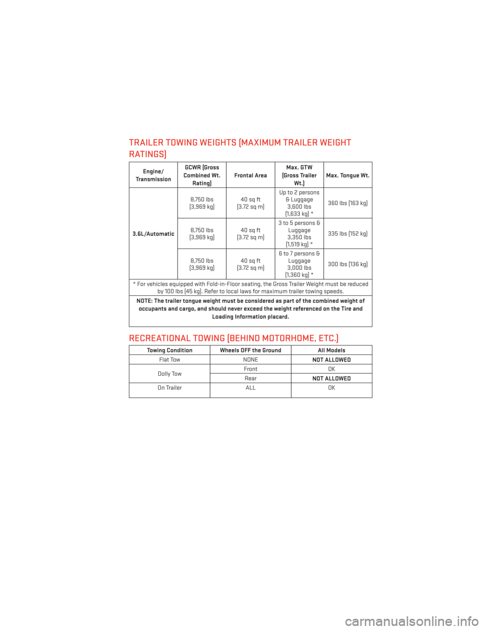
TRAILER TOWING WEIGHTS (MAXIMUM TRAILER WEIGHT
RATINGS)
Engine/
Transmission GCWR (Gross
Combined Wt. Rating) Frontal Area Max. GTW
(Gross Trailer Wt.) Max. Tongue Wt.
3.6L/Automatic 8,750 lbs
(3,969 kg) 40 sq ft
(3.72sqm) Up to 2 persons
& Luggage3,600 lbs
(1,633 kg) * 360 lbs (163 kg)
8,750 lbs
(3,969 kg) 40 sq ft
(3.72sqm) 3 to 5 persons &
Luggage
3,350 lbs
(1,519 kg) * 335 lbs (152 kg)
8,750 lbs
(3,969 kg) 40 sq ft
(3.72sqm) 6 to 7 persons &
Luggage
3,000 lbs
(1,360 kg) * 300 lbs (136 kg)
* For vehicles equipped with Fold-in-Floor seating, the Gross Trailer Weight must be reduced by 100 lbs (45 kg). Refer to local laws for maximum trailer towing speeds.
NOTE: The trailer tongue weight must be considered as part of the combined weight of occupants and cargo, and should never exceed the weight referenced on the Tire and Loading Information placard.
RECREATIONAL TOWING (BEHIND MOTORHOME, ETC.)
Towing Condition Wheels OFF the Ground All Models
Flat Tow NONE
NOT ALLOWED
Dolly Tow Front
OK
Rear NOT ALLOWED
On Trailer ALLOK
UTILITY
93
Page 96 of 156
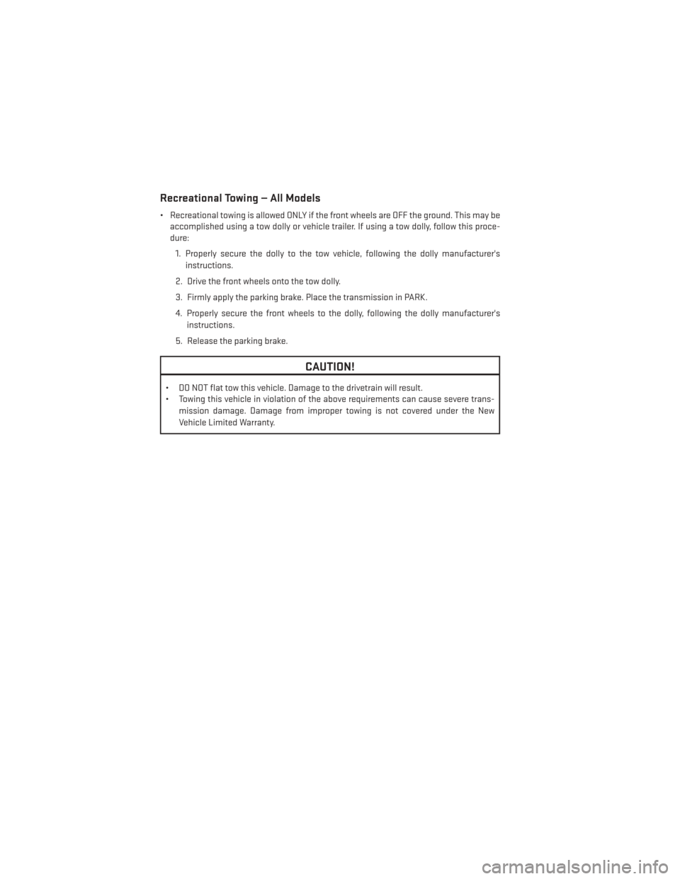
Recreational Towing — All Models
• Recreational towing is allowed ONLY if the front wheels are OFF the ground. This may beaccomplished using a tow dolly or vehicle trailer. If using a tow dolly, follow this proce-
dure:
1. Properly secure the dolly to the tow vehicle, following the dolly manufacturer's instructions.
2. Drive the front wheels onto the tow dolly.
3. Firmly apply the parking brake. Place the transmission in PARK.
4. Properly secure the front wheels to the dolly, following the dolly manufacturer's instructions.
5. Release the parking brake.
CAUTION!
• DO NOT flat tow this vehicle. Damage to the drivetrain will result.
• Towing this vehicle in violation of the above requirements can cause severe trans- mission damage. Damage from improper towing is not covered under the New
Vehicle Limited Warranty.
UTILITY
94
Page 99 of 156
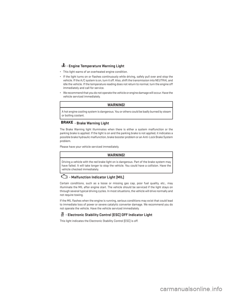
- Engine Temperature Warning Light
• This light warns of an overheated engine condition.
• If the light turns on or flashes continuously while driving, safely pull over and stop thevehicle. If the A/C system is on, turn it off. Also, shift the transmission into NEUTRAL and
idle the vehicle. If the temperature reading does not return to normal, turn the engine off
immediately and call for service.
• We recommend that you do not operate the vehicle or engine damage will occur. Have the vehicle serviced immediately.
WARNING!
A hot engine cooling system is dangerous. You or others could be badly burned by steam
or boiling coolant.
BRAKE- Brake Warning Light
The Brake Warning light illuminates when there is either a system malfunction or the
parking brake is applied. If the light is on and the parking brake is not applied, it indicates a
possible brake hydraulic malfunction, brake booster problem or an Anti-Lock Brake System
problem.
Please have your vehicle serviced immediately.
WARNING!
Driving a vehicle with the red brake light on is dangerous. Part of the brake system may
have failed. It will take longer to stop the vehicle. You could have a collision. Have the
vehicle checked immediately.
- Malfunction Indicator Light (MIL)
Certain conditions, such as a loose or missing gas cap, poor fuel quality, etc., may
illuminate the MIL after engine start. The vehicle should be serviced if the light stays on
through several typical driving cycles. In most situations, the vehicle will drive normally and
not require towing.
If the MIL flashes when the engine is running, serious conditions may exist that could lead
to immediate loss of power or severe catalytic converter damage. We recommend you do
not operate the vehicle. Have the vehicle serviced immediately.
- Electronic Stability Control (ESC) OFF Indicator Light
This light indicates the Electronic Stability Control (ESC) is off.
WHAT TO DO IN EMERGENCIES
97
Page 100 of 156
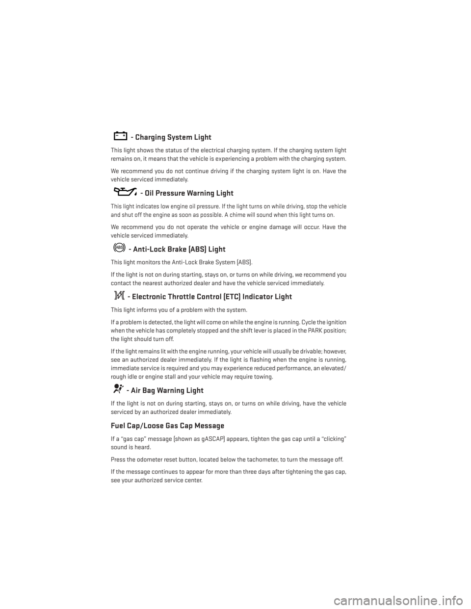
- Charging System Light
This light shows the status of the electrical charging system. If the charging system light
remains on, it means that the vehicle is experiencing a problem with the charging system.
We recommend you do not continue driving if the charging system light is on. Have the
vehicle serviced immediately.
- Oil Pressure Warning Light
This light indicates low engine oil pressure. If the light turns on while driving, stop the vehicle
and shut off the engine as soon as possible. A chime will sound when this light turns on.
We recommend you do not operate the vehicle or engine damage will occur. Have the
vehicle serviced immediately.
- Anti-Lock Brake (ABS) Light
This light monitors the Anti-Lock Brake System (ABS).
If the light is not on during starting, stays on, or turns on while driving, we recommend you
contact the nearest authorized dealer and have the vehicle serviced immediately.
- Electronic Throttle Control (ETC) Indicator Light
This light informs you of a problem with the system.
If a problem is detected, the light will come on while the engine is running. Cycle the ignition
when the vehicle has completely stopped and the shift lever is placed in the PARK position;
the light should turn off.
If the light remains lit with the engine running, your vehicle will usually be drivable; however,
see an authorized dealer immediately. If the light is flashing when the engine is running,
immediate service is required and you may experience reduced performance, an elevated/
rough idle or engine stall and your vehicle may require towing.
- Air Bag Warning Light
If the light is not on during starting, stays on, or turns on while driving, have the vehicle
serviced by an authorized dealer immediately.
Fuel Cap/Loose Gas Cap Message
If a “gas cap” message (shown as gASCAP) appears, tighten the gas cap until a “clicking”
sound is heard.
Press the odometer reset button, located below the tachometer, to turn the message off.
If the message continues to appear for more than three days after tightening the gas cap,
see your authorized service center.
WHAT TO DO IN EMERGENCIES
98
Page 102 of 156
CAUTION!
Driving with a hot cooling system could damage your vehicle. If the temperature gauge
reads HOT (H), pull over and stop the vehicle. Idle the vehicle with the air conditioner
turned off until the pointer drops back into the normal range. If the pointer remains on
HOT (H), and you hear continuous chimes, turn the engine off immediately, and call for
service.
WARNING!
You or others can be badly burned by hot engine coolant (antifreeze) or steam from your
radiator. If you see or hear steam coming from under the hood, do not open the hood until
the radiator has had time to cool. Never try to open a cooling system pressure cap when
the radiator or coolant bottle is hot.
TIREFIT KIT
Your vehicle may be equipped with a TIREFIT Kit.
Small punctures up to 1/4” (6 mm) in the tire tread can be sealed with TIREFIT. Foreign
objects (e.g., screws or nails) should not be removed from the tire. TIREFIT can be used in
outside temperatures down to approximately -4°F (-20°C).
This kit will provide a temporary tire seal, allowing you to drive your vehicle up to 100 miles
(160 km) with a maximum speed of 55 mph (90 km/h).
TIREFIT Storage
• The TIREFIT kit is stowed behind the rear left side trim panel in the rear cargo area.
WHAT TO DO IN EMERGENCIES
100
Page 108 of 156
WARNING!
• Do not attempt to seal a tire on the side of the vehicle closest to traffic. Pull farenough off the road to avoid the danger of being hit when using the TIREFIT kit.
• Do not use TIREFIT or drive the vehicle under the following circumstances:
• If the puncture in the tire tread is approximately 1/4”. (6 mm) or larger.
• If the tire has any sidewall damage.
• If the tire has any damage from driving with extremely low tire pressure.
• If the tire has any damage from driving on a flat tire.
• If the wheel has any damage.
• If you are unsure of the condition of the tire or the wheel.
• Keep TIREFIT away from open flames or heat source.
• A loose TIREFIT kit thrown forward in a collision or hard stop could endanger the
occupants of the vehicle. Always stow the TIREFIT kit in the place provided. Failure to
follow these warnings can result in injuries that are serious or fatal to you, your
passengers, and others around you.
• Take care not to allow the contents of TIREFIT to come in contact with hair, eyes, or
clothing. TIREFIT is harmful if inhaled, swallowed, or absorbed through the skin. It
causes skin, eye, and respiratory irritation. Flush immediately with plenty of water if
there is any contact with eyes or skin. Change clothing as soon as possible, if there is
any contact with clothing.
• TIREFIT Sealant solution contains latex. In case of an allergic reaction or rash,
consult a physician immediately. Keep TIREFIT out of reach of children. If swallowed,
rinse mouth immediately with plenty of water and drink plenty of water. Do not induce
vomiting! Consult a physician immediately.
• TIREFIT is not a permanent flat tire repair. Have the tire inspected and repaired or
replaced after using TIREFIT. Do not exceed 55 mph (88 km/h) until the tire is
repaired or replaced. Failure to follow this warning can result in injuries that are
serious or fatal to you, your passengers, and others around you.
WHAT TO DO IN EMERGENCIES
106
Page 109 of 156
JACKING AND TIRE CHANGING
Jack Location
• Your vehicle may be equipped with jack-ing and tire changing equipment.
• The jack, jack handle and winch handle tools are stowed behind the rear left side
trim panel in the rear cargo area. Turn the
two cover latches to release the cover.
• Remove the pouch containing the scis- sors jack, jack handle, and tools.
Spare Tire Removal
• The spare tire is stowed inside a protec-tive cover located under the center of the
vehicle between the front doors by means
of a cable winch mechanism. The “spare
tire drive” nut is located on the floor, under
a plastic cap at the front of the floor con-
sole or under front super console forward bin liner.
Jack Location
WHAT TO DO IN EMERGENCIES
107
Page 117 of 156
10. Place the deflated (flat) tire and compact spare tire cover assembly in the rear cargoarea. Do not stow the deflated tire in the spare tire location. Have the full-sized tire
repaired or replaced, as soon as possible.
11. Stow the cable and wheel spacer before driving the vehicle. Reassemble the winch handle extensions to form a “T” and fit the winch T-handle over the drive nut. Rotate the
nut to the right until the winch mechanism clicks at least three times.
NOTE:
Refer to the “Spare Tire Tools” section for instructions on assembling the T-handle.
12. Stow the jack, jack handle and winch handle tools back in the stowage compartment.
13. Check the compact spare tire pressure as soon as possible. Correct the tire pressure, as required.
Securing The Spare Tire
1. Assemble the winch handle extensions to form a T-handle and fit the winch T-handle overthe drive nut. Rotate the nut to the left until the winch mechanism stops turning freely.
This will allow enough slack in the cable to allow you to pull the wheel spacer out from
under the vehicle.
2. Assemble the winch handle extensions to form the spare tire hook, and pull the wheel spacer from under the vehicle.
3. Turn the compact spare tire so that the valve stem is down, and place the tire into the spare tire/cover assembly. Slide the wheel spacer through the center of the wheel and
spare tire/cover assembly, so that the two retainer tabs snap out and engage the spare
tire cover on the opposite side.
4. Using the winch T-handle, rotate the drive nut to the right until the compact spare tire/cover assembly is drawn into place against the underside of the vehicle.
5. Continue to rotate the nut to the right until you hear the winch mechanism click three times. It cannot be overtightened. Check under the vehicle to ensure the compact spare
tire/cover assembly is positioned correctly against the underside of the vehicle.
WHAT TO DO IN EMERGENCIES
115
Page 118 of 156
Road Tire Installation
Vehicles Equipped With Wheel Covers
1. Mount the road tire on the axle.
2. To ease the installation process for steel wheels with wheel covers, install two lug nutson the mounting studs which are on each side of the valve stem. Install the lug nuts with
the cone shaped end of the nut toward the wheel. Lightly tighten the lug nuts.
3. Align the valve notch in the wheel cover with the valve stem on the wheel. Install
the cover by hand, snapping the cover
over the two lug nuts. Do not use a ham-
mer or excessive force to install the
cover.
4. Install the remaining lug nuts with the cone shaped end of the nut toward the
wheel. Lightly tighten the lug nuts.
5. Lower the vehicle to the ground by turn- ing the jack handle counterclockwise.
6. Finish tightening the lug nuts. Push down on the wrench while at the end of the
handle for increased leverage. Tighten
the lug nuts in a star pattern until each
nut has been tightened twice. The correct
tightness of each lug nut is 100 ft/lbs
(135 N·m). If in doubt about the correct
tightness, have them checked with a torque wrench by your authorized dealer or service
station.
7. After 25 miles (40 km) check the lug nut torque with a torque wrench to ensure that all lug nuts are properly seated against the wheel.
Wheel Cover Installation
1 — Valve Stem
2 — Valve Notch
3 — Wheel Lug Nut
4 — Wheel Cover
5 — Mounting Stud
WHAT TO DO IN EMERGENCIES
116
Page 119 of 156
Vehicles Without Wheel Covers
1. Mount the road tire on the axle.
2. Install the remaining lug nuts with the cone shaped end of the nut toward the wheel.Lightly tighten the lug nuts.
3. Lower the vehicle to the ground by turning the jack handle counterclockwise.
4. Finish tightening the lug nuts. Push down on the wrench while at the end of the handle for increased leverage. Tighten the lug nuts in a star pattern until each nut has been
tightened twice. The correct tightness of each lug nut is 100 ft/lbs (135 N·m). If in doubt
about the correct tightness, have them checked with a torque wrench by your authorized
dealer or service station.
5. After 25 miles (40 km) check the lug nut torque with a torque wrench to ensure that all lug nuts are properly seated against the wheel.
CAUTION!
• The winch mechanism is designed for use with the winch T-handle only. Use of air wrench or other power tools is not recommended and can damage the winch.
• Do not attempt to raise the vehicle by jacking on locations other than those indicated
in the Jacking Instructions for this vehicle.
• Be sure to mount the spare tire with the valve stem facing outward. The vehicle could
be damaged if the spare tire is mounted incorrectly.
• The compact spare tire/cover assembly must be used when the compact spare tire is
stored. Failure to use this cover could drastically reduce the life of the compact spare
tire.
• The winch mechanism is designed specifically to stow a compact spare tire only. Do
not attempt to use the winch to stow the full size flat tire, or any other full-size tire.
Vehicle damage may result.
WHAT TO DO IN EMERGENCIES
117