wheel DODGE GRAND CARAVAN 2014 5.G Owner's Manual
[x] Cancel search | Manufacturer: DODGE, Model Year: 2014, Model line: GRAND CARAVAN, Model: DODGE GRAND CARAVAN 2014 5.GPages: 156, PDF Size: 3.83 MB
Page 116 of 156
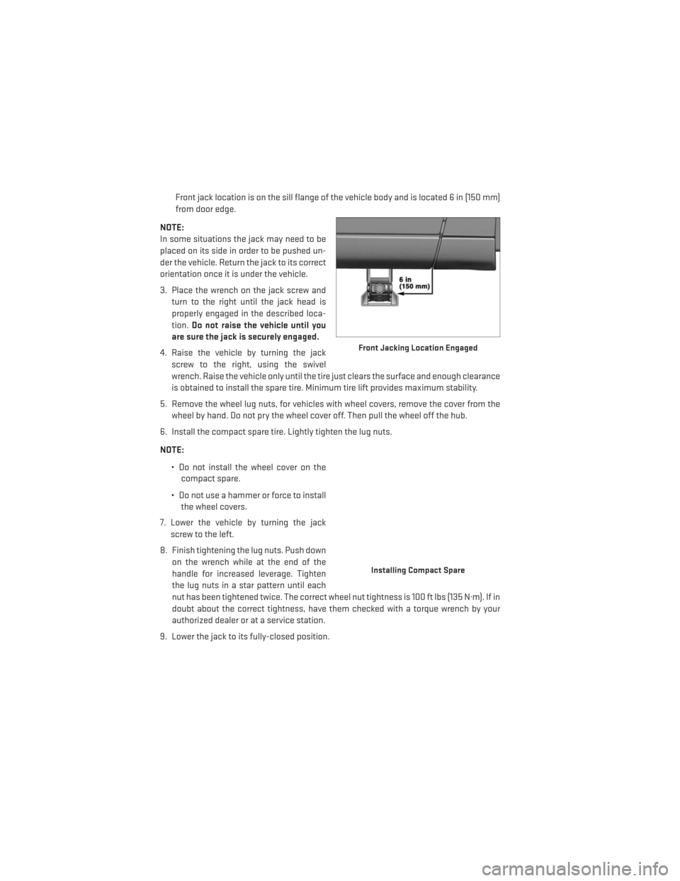
Front jack location is on the sill flange of the vehicle body and is located 6 in (150 mm)
from door edge.
NOTE:
In some situations the jack may need to be
placed on its side in order to be pushed un-
der the vehicle. Return the jack to its correct
orientation once it is under the vehicle.
3. Place the wrench on the jack screw and turn to the right until the jack head is
properly engaged in the described loca-
tion. Do not raise the vehicle until you
are sure the jack is securely engaged.
4. Raise the vehicle by turning the jack screw to the right, using the swivel
wrench. Raise the vehicle only until the tire just clears the surface and enough clearance
is obtained to install the spare tire. Minimum tire lift provides maximum stability.
5. Remove the wheel lug nuts, for vehicles with wheel covers, remove the cover from the wheel by hand. Do not pry the wheel cover off. Then pull the wheel off the hub.
6. Install the compact spare tire. Lightly tighten the lug nuts.
NOTE:
• Do not install the wheel cover on thecompact spare.
• Do not use a hammer or force to install the wheel covers.
7. Lower the vehicle by turning the jack screw to the left.
8. Finish tightening the lug nuts. Push down on the wrench while at the end of the
handle for increased leverage. Tighten
the lug nuts in a star pattern until each
nut has been tightened twice. The correct wheel nut tightness is 100 ft lbs (135 N·m). If in
doubt about the correct tightness, have them checked with a torque wrench by your
authorized dealer or at a service station.
9. Lower the jack to its fully-closed position.
Front Jacking Location Engaged
Installing Compact Spare
WHAT TO DO IN EMERGENCIES
114
Page 117 of 156
10. Place the deflated (flat) tire and compact spare tire cover assembly in the rear cargoarea. Do not stow the deflated tire in the spare tire location. Have the full-sized tire
repaired or replaced, as soon as possible.
11. Stow the cable and wheel spacer before driving the vehicle. Reassemble the winch handle extensions to form a “T” and fit the winch T-handle over the drive nut. Rotate the
nut to the right until the winch mechanism clicks at least three times.
NOTE:
Refer to the “Spare Tire Tools” section for instructions on assembling the T-handle.
12. Stow the jack, jack handle and winch handle tools back in the stowage compartment.
13. Check the compact spare tire pressure as soon as possible. Correct the tire pressure, as required.
Securing The Spare Tire
1. Assemble the winch handle extensions to form a T-handle and fit the winch T-handle overthe drive nut. Rotate the nut to the left until the winch mechanism stops turning freely.
This will allow enough slack in the cable to allow you to pull the wheel spacer out from
under the vehicle.
2. Assemble the winch handle extensions to form the spare tire hook, and pull the wheel spacer from under the vehicle.
3. Turn the compact spare tire so that the valve stem is down, and place the tire into the spare tire/cover assembly. Slide the wheel spacer through the center of the wheel and
spare tire/cover assembly, so that the two retainer tabs snap out and engage the spare
tire cover on the opposite side.
4. Using the winch T-handle, rotate the drive nut to the right until the compact spare tire/cover assembly is drawn into place against the underside of the vehicle.
5. Continue to rotate the nut to the right until you hear the winch mechanism click three times. It cannot be overtightened. Check under the vehicle to ensure the compact spare
tire/cover assembly is positioned correctly against the underside of the vehicle.
WHAT TO DO IN EMERGENCIES
115
Page 118 of 156
Road Tire Installation
Vehicles Equipped With Wheel Covers
1. Mount the road tire on the axle.
2. To ease the installation process for steel wheels with wheel covers, install two lug nutson the mounting studs which are on each side of the valve stem. Install the lug nuts with
the cone shaped end of the nut toward the wheel. Lightly tighten the lug nuts.
3. Align the valve notch in the wheel cover with the valve stem on the wheel. Install
the cover by hand, snapping the cover
over the two lug nuts. Do not use a ham-
mer or excessive force to install the
cover.
4. Install the remaining lug nuts with the cone shaped end of the nut toward the
wheel. Lightly tighten the lug nuts.
5. Lower the vehicle to the ground by turn- ing the jack handle counterclockwise.
6. Finish tightening the lug nuts. Push down on the wrench while at the end of the
handle for increased leverage. Tighten
the lug nuts in a star pattern until each
nut has been tightened twice. The correct
tightness of each lug nut is 100 ft/lbs
(135 N·m). If in doubt about the correct
tightness, have them checked with a torque wrench by your authorized dealer or service
station.
7. After 25 miles (40 km) check the lug nut torque with a torque wrench to ensure that all lug nuts are properly seated against the wheel.
Wheel Cover Installation
1 — Valve Stem
2 — Valve Notch
3 — Wheel Lug Nut
4 — Wheel Cover
5 — Mounting Stud
WHAT TO DO IN EMERGENCIES
116
Page 119 of 156
Vehicles Without Wheel Covers
1. Mount the road tire on the axle.
2. Install the remaining lug nuts with the cone shaped end of the nut toward the wheel.Lightly tighten the lug nuts.
3. Lower the vehicle to the ground by turning the jack handle counterclockwise.
4. Finish tightening the lug nuts. Push down on the wrench while at the end of the handle for increased leverage. Tighten the lug nuts in a star pattern until each nut has been
tightened twice. The correct tightness of each lug nut is 100 ft/lbs (135 N·m). If in doubt
about the correct tightness, have them checked with a torque wrench by your authorized
dealer or service station.
5. After 25 miles (40 km) check the lug nut torque with a torque wrench to ensure that all lug nuts are properly seated against the wheel.
CAUTION!
• The winch mechanism is designed for use with the winch T-handle only. Use of air wrench or other power tools is not recommended and can damage the winch.
• Do not attempt to raise the vehicle by jacking on locations other than those indicated
in the Jacking Instructions for this vehicle.
• Be sure to mount the spare tire with the valve stem facing outward. The vehicle could
be damaged if the spare tire is mounted incorrectly.
• The compact spare tire/cover assembly must be used when the compact spare tire is
stored. Failure to use this cover could drastically reduce the life of the compact spare
tire.
• The winch mechanism is designed specifically to stow a compact spare tire only. Do
not attempt to use the winch to stow the full size flat tire, or any other full-size tire.
Vehicle damage may result.
WHAT TO DO IN EMERGENCIES
117
Page 120 of 156
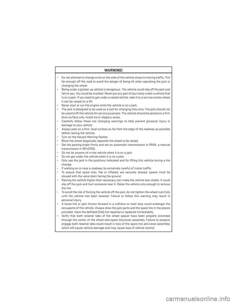
WARNING!
• Do not attempt to change a tire on the side of the vehicle close to moving traffic. Pullfar enough off the road to avoid the danger of being hit when operating the jack or
changing the wheel.
• Being under a jacked-up vehicle is dangerous. The vehicle could slip off the jack and
fall on you. You could be crushed. Never put any part of your body under a vehicle that
is on a jack. If you need to get under a raised vehicle, take it to a service center where
it can be raised on a lift.
• Never start or run the engine while the vehicle is on a jack.
• The jack is designed to be used as a tool for changing tires only. The jack should not
be used to lift the vehicle for service purposes. The vehicle should be jacked on a firm
level surface only. Avoid ice or slippery areas.
• Carefully follow these tire changing warnings to help prevent personal injury or
damage to your vehicle:
• Always park on a firm, level surface as far from the edge of the roadway as possible
before raising the vehicle.
• Turn on the Hazard Warning flasher.
• Block the wheel diagonally opposite the wheel to be raised.
• Set the parking brake firmly and set an automatic transmission in PARK; a manual
transmission in REVERSE.
• Do not let anyone sit in the vehicle when it is on a jack.
• Do not get under the vehicle when it is on a jack.
• Only use the jack in the positions indicated and for lifting this vehicle during a tire
change.
• If working on or near a roadway, be extremely careful of motor traffic.
• To assure that spare tires, flat or inflated, are securely stowed, spares must be
stowed with the valve stem facing the ground.
• Raising the vehicle higher than necessary can make the vehicle less stable. It could
slip off the jack and hurt someone near it. Raise the vehicle only enough to remove
the tire.
• To avoid the risk of forcing the vehicle off the jack, do not tighten the wheel nuts fully
until the vehicle has been lowered. Failure to follow this warning may result in
personal injury.
• A loose tire or jack thrown forward in a collision or hard stop could endanger the
occupants of the vehicle. Always stow the jack parts and the spare tire in the places
provided. Have the deflated (flat) tire repaired or replaced immediately.
• Verify that both retainer tabs of the wheel spacer have been properly extended
through the center of the wheel and spare tire/cover assembly. Failure to properly
engage both retainer tabs could result in loss of the spare tire and cover assembly,
which will cause vehicle damage and may cause loss of vehicle control.
WHAT TO DO IN EMERGENCIES
118
Page 123 of 156
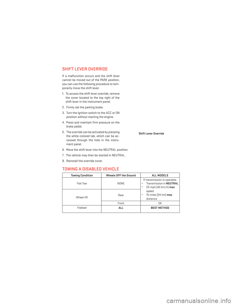
SHIFT LEVER OVERRIDE
If a malfunction occurs and the shift lever
cannot be moved out of the PARK position,
you can use the following procedure to tem-
porarily move the shift lever:
1. To access the shift lever override, removethe cover located to the top right of the
shift lever in the instrument panel.
2. Firmly set the parking brake.
3. Turn the ignition switch to the ACC or ON position without starting the engine.
4. Press and maintain firm pressure on the brake pedal.
5. The override can be activated by pressing the white-colored tab, which can be ac-
cessed through the hole in the instru-
ment panel.
6. Move the shift lever into the NEUTRAL position.
7. The vehicle may then be started in NEUTRAL.
8. Reinstall the override cover.
TOWING A DISABLED VEHICLE
Towing Condition Wheels OFF the Ground ALL MODELS
Flat Tow NONEIf transmission is operable:
• Transmission in NEUTRAL
• 25 mph (40 km/h) max
speed
• 15 miles (24 km) max
distance
Wheel lift Rear
Front OK
Flatbed ALLBEST METHOD
Shift Lever Override
WHAT TO DO IN EMERGENCIES
121
Page 124 of 156
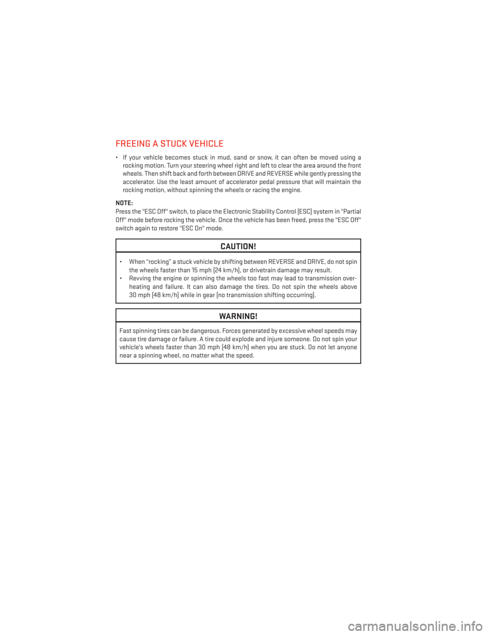
FREEING A STUCK VEHICLE
• If your vehicle becomes stuck in mud, sand or snow, it can often be moved using arocking motion. Turn your steering wheel right and left to clear the area around the front
wheels. Then shift back and forth between DRIVE and REVERSE while gently pressing the
accelerator. Use the least amount of accelerator pedal pressure that will maintain the
rocking motion, without spinning the wheels or racing the engine.
NOTE:
Press the "ESC Off" switch, to place the Electronic Stability Control (ESC) system in "Partial
Off" mode before rocking the vehicle. Once the vehicle has been freed, press the "ESC Off"
switch again to restore "ESC On" mode.
CAUTION!
• When “rocking” a stuck vehicle by shifting between REVERSE and DRIVE, do not spin the wheels faster than 15 mph (24 km/h), or drivetrain damage may result.
• Revving the engine or spinning the wheels too fast may lead to transmission over-
heating and failure. It can also damage the tires. Do not spin the wheels above
30 mph (48 km/h) while in gear (no transmission shifting occurring).
WARNING!
Fast spinning tires can be dangerous. Forces generated by excessive wheel speeds may
cause tire damage or failure. A tire could explode and injure someone. Do not spin your
vehicle's wheels faster than 30 mph (48 km/h) when you are stuck. Do not let anyone
near a spinning wheel, no matter what the speed.
WHAT TO DO IN EMERGENCIES
122
Page 137 of 156
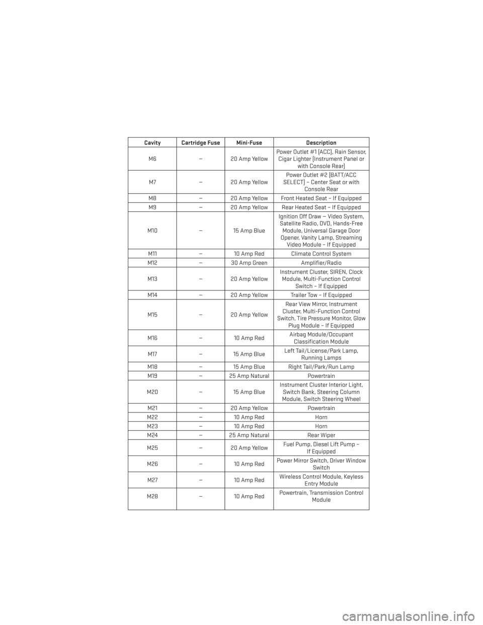
Cavity Cartridge Fuse Mini-FuseDescription
M6 — 20 Amp Yellow Power Outlet #1 (ACC), Rain Sensor,
Cigar Lighter (Instrument Panel or with Console Rear)
M7 — 20 Amp Yellow Power Outlet #2 (BATT/ACC
SELECT) – Center Seat or with Console Rear
M8 — 20 Amp Yellow Front Heated Seat – If Equipped
M9 — 20 Amp Yellow Rear Heated Seat – If Equipped
M10 — 15 Amp Blue Ignition Off Draw — Video System,
Satellite Radio, DVD, Hands-Free Module, Universal Garage Door
Opener, Vanity Lamp, Streaming Video Module – If Equipped
M11 — 10 Amp Red Climate Control System
M12 — 30 Amp Green Amplifier/Radio
M13 — 20 Amp Yellow Instrument Cluster, SIREN, Clock
Module, Multi-Function Control Switch – If Equipped
M14 — 20 Amp Yellow Trailer Tow – If Equipped
M15 — 20 Amp Yellow Rear View Mirror, Instrument
Cluster, Multi-Function Control
Switch, Tire Pressure Monitor, Glow Plug Module – If Equipped
M16 — 10 Amp Red Airbag Module/Occupant
Classification Module
M17 — 15 Amp Blue Left Tail/License/Park Lamp,
Running Lamps
M18 — 15 Amp Blue Right Tail/Park/Run Lamp
M19 — 25 Amp Natural Powertrain
M20 — 15 Amp Blue Instrument Cluster Interior Light,
Switch Bank, Steering Column
Module, Switch Steering Wheel
M21 — 20 Amp Yellow Powertrain
M22 — 10 Amp Red Horn
M23 — 10 Amp Red Horn
M24 — 25 Amp Natural Rear Wiper
M25 — 20 Amp Yellow Fuel Pump, Diesel Lift Pump –
If Equipped
M26 — 10 Amp Red Power Mirror Switch, Driver Window
Switch
M27 — 10 Amp Red Wireless Control Module, Keyless
Entry Module
M28 — 10 Amp Red Powertrain, Transmission Control
Module
MAINTAINING YOUR VEHICLE
135
Page 139 of 156
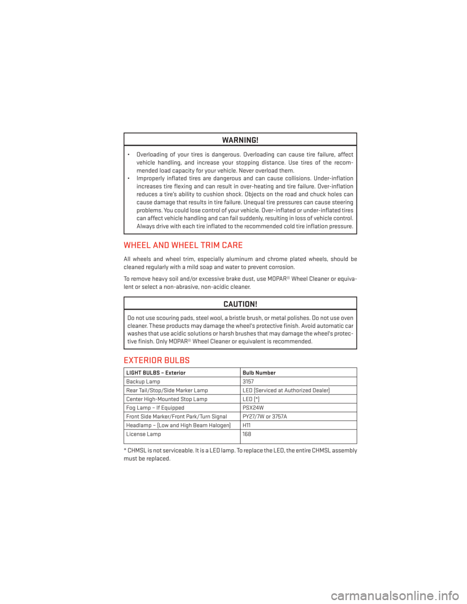
WARNING!
• Overloading of your tires is dangerous. Overloading can cause tire failure, affectvehicle handling, and increase your stopping distance. Use tires of the recom-
mended load capacity for your vehicle. Never overload them.
• Improperly inflated tires are dangerous and can cause collisions. Under-inflation
increases tire flexing and can result in over-heating and tire failure. Over-inflation
reduces a tire’s ability to cushion shock. Objects on the road and chuck holes can
cause damage that results in tire failure. Unequal tire pressures can cause steering
problems. You could lose control of your vehicle. Over-inflated or under-inflated tires
can affect vehicle handling and can fail suddenly, resulting in loss of vehicle control.
Always drive with each tire inflated to the recommended cold tire inflation pressure.
WHEEL AND WHEEL TRIM CARE
All wheels and wheel trim, especially aluminum and chrome plated wheels, should be
cleaned regularly with a mild soap and water to prevent corrosion.
To remove heavy soil and/or excessive brake dust, use MOPAR® Wheel Cleaner or equiva-
lent or select a non-abrasive, non-acidic cleaner.
CAUTION!
Do not use scouring pads, steel wool, a bristle brush, or metal polishes. Do not use oven
cleaner. These products may damage the wheel's protective finish. Avoid automatic car
washes that use acidic solutions or harsh brushes that may damage the wheel's protec-
tive finish. Only MOPAR® Wheel Cleaner or equivalent is recommended.
EXTERIOR BULBS
LIGHT BULBS – Exterior Bulb Number
Backup Lamp 3157
Rear Tail/Stop/Side Marker Lamp LED (Serviced at Authorized Dealer)
Center High-Mounted Stop Lamp LED (*)
Fog Lamp – If Equipped PSX24W
Front Side Marker/Front Park/Turn Signal PY27/7W or 3757A
Headlamp – (Low and High Beam Halogen) H11
License Lamp 168
* CHMSL is not serviceable. It is a LED lamp. To replace the LED, the entire CHMSL assembly
must be replaced.
MAINTAINING YOUR VEHICLE
137
Page 146 of 156
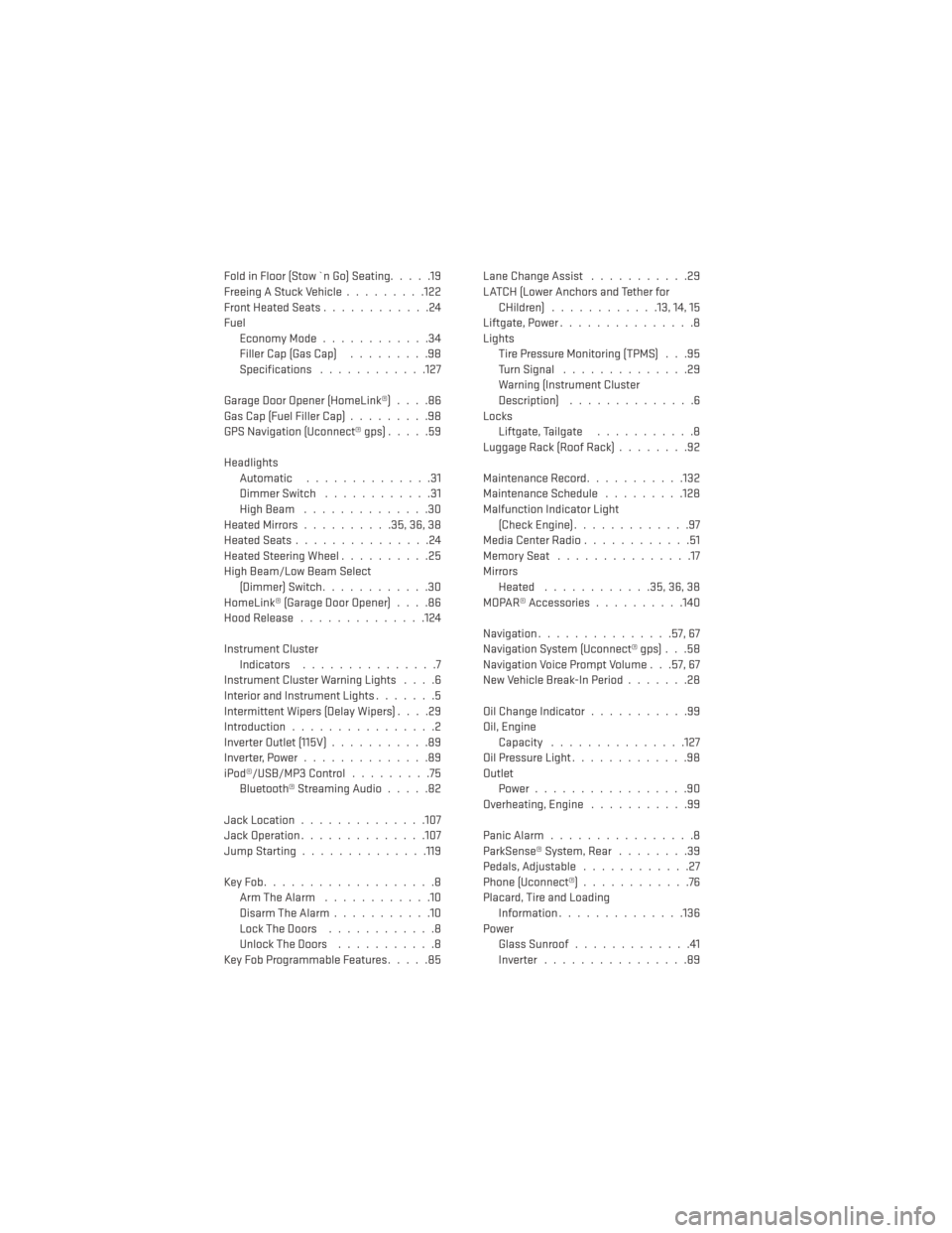
Fold in Floor (Stow `n Go) Seating.....19
Freeing A Stuck Vehicle .........122
Front Heated Seats ............24
Fuel Economy Mode ............34
Filler Cap (Gas Cap) .........98
Specifications ............127
GarageDoorOpener(HomeLink®)....86
Gas Cap (Fuel Filler Cap) .........98
GPS Navigation (Uconnect® gps) .....59
Headlights Automatic ..............31
Dimmer Switch ............31
HighBeam ..............30
HeatedMirrors..........35,36,38
HeatedSeats...............24
Heated Steering Wheel ..........25
High Beam/Low Beam Select (Dimmer) Switch ............30
HomeLink® (Garage Door Opener) ....86
Hood Release ..............124
Instrument Cluster Indicators ...............7
Instrument Cluster Warning Lights ....6
Interior and Instrument Lights .......5
Intermittent Wipers (Delay Wipers) ....29
Introduction ................2
Inverter Outlet (115V) ...........89
Inverter,Power..............89
iPod®/USB/MP3 Control .........75
Bluetooth®StreamingAudio.....82
Jack Location ..............107
Jack Operation ..............107
Jump Starting ..............119
KeyFob...................8 Arm The Alarm ............10
Disarm The Alarm ...........10
LockTheDoors ............8
Unlock The Doors ...........8
Key Fob Programmable Features .....85Lane Change Assist
...........29
LATCH (Lower Anchors and Tether for CHildren) ............13, 14, 15
Liftgate, Power ...............8
Lights Tire Pressure Monitoring (TPMS) . . .95
TurnSignal ..............29
Warning (Instrument Cluster
Description) ..............6
Locks Liftgate, Tailgate ...........8
LuggageRack(RoofRack)........92
Maintenance Record ...........132
Maintenance Schedule .........128
Malfunction Indicator Light (Check Engine) .............97
Media Center Radio ............51
MemorySeat ...............17
Mirrors Heated ............35,36,38
MOPAR® Accessories ..........140
Navigation ...............57,67
Navigation System (Uconnect® gps) . . .58
Navigation Voice Prompt Volume . . .57, 67
New Vehicle Break-In Period .......28
Oil Change Indicator ...........99
Oil, Engine Capacity ...............127
Oil Pressure Light .............98
Outlet P
ower.................90
Overheating, Engine ...........99
Panic Alarm ................8
ParkSense® System, Rear ........39
Pedals,Adjustable ............27
Phone (Uconnect®) ............76
Placard, Tire and Loading Information ..............136
Power Glass Sunroof .............41
Inverter ................89
INDEX
144