jacking DODGE GRAND CARAVAN 2014 5.G User Guide
[x] Cancel search | Manufacturer: DODGE, Model Year: 2014, Model line: GRAND CARAVAN, Model: DODGE GRAND CARAVAN 2014 5.GPages: 156, PDF Size: 3.83 MB
Page 3 of 156
INTRODUCTION/WELCOME
WELCOME FROM CHRYSLER GROUP LLC . . . 2
CONTROLS AT A GLANCE
DRIVER COCKPIT................4
INSTRUMENT CLUSTER .............6
GETTING STARTED
KEYFOB .....................8
REMOTE START.................9
VEHICLE SECURITY ALARM ..........10
SEATBELT ...................10
SUPPLEMENTAL RESTRAINT SYSTEM (SRS) —
AIRBAGS ....................11
CHILD RESTRAINTS ..............12
FRONT SEATS .................16
REARSEATS ..................19
HEATEDSEATS ................24
HEATED STEERING WHEEL ..........25
TILT/TELESCOPING STEERING COLUMN . . . 26
ADJUSTABLE PEDALS .............27
OPERATING YOUR VEHICLE
ENGINE BREAK-IN RECOMMENDATIONS . . . 28
TURN SIGNAL/WIPER/WASHER/HIGH
BEAM LEVER..................29
HEADLIGHT SWITCH AND HALO LIGHT
SWITCH .....................31
SPEED CONTROL ................32
ELECTRONIC RANGE SELECTION (ERS) . . . 34
FUEL ECONOMY (ECON) MODE ........34
MANUAL CLIMATE CONTROLS ........35
THREE ZONE MANUAL CLIMATE CONTROLS . . 36THREE ZONE AUTOMATIC TEMPERATURE
CONTROLS (ATC)................37
PARKSENSE® REAR PARK ASSIST ......39
PARKVIEW® REAR BACK-UP CAMERA ....39
BLIND SPOT MONITORING WITH REAR
CROSS PATH ..................39
POWER SLIDING SIDE DOORS .........40
POWER LIFTGATE ................41
POWER SUNROOF ...............41
WIND BUFFETING ...............43
ELECTRONICS
YOUR VEHICLE'S SOUND SYSTEM ......44
Uconnect® 130 .................46
Uconnect® 130 WITH SiriusXM
SATELLITE RADIO ...............48
Uconnect® 430/430N .............51
Uconnect® 730N ................60
SiriusXM SATELLITE RADIO/TRAVEL LINK . . 71
STEERING WHEEL AUDIO CONTROLS ....75
iPod®/USB/MP3 CONTROL ..........75
Uconnect® PHONE ...............76
Uconnect® VOICE COMMAND .........79
Bluetooth® STREAMING AUDIO ........82VIDEO ENTERTAINMENT SYSTEM (VES™) . . 82
ELECTRONIC VEHICLE INFORMATION
CENTER (EVIC)
.................84
PROGRAMMABLE FEATURES .........85
UNIVERSAL GARAGE DOOR OPENER
(HomeLink®) ..................86
POWER INVERTER ...............89
POWER OUTLETS ...............90
UTILITY
IN-FLOORSTORAGE—STOW'NGO® .....92
ROOF LUGGAGE RACK .............92
TRAILER TOWING WEIGHTS
(MAXIMUM TRAILER WEIGHT RATINGS) . . . 93
RECREATIONAL TOWING
(BEHIND MOTORHOME, ETC.) .........93
WHAT TO DO IN EMERGENCIES
ROADSIDE ASSISTANCE............95
INSTRUMENT CLUSTER WARNING LIGHTS . . 95
IF YOUR ENGINE OVERHEATS .........99
TIREFIT KIT ..................100
JACKING AND TIRE CHANGING .......107
JUMP-STARTING ...............119
SHIFT LEVER OVERRIDE ...........121
TOWING A DISABLED VEHICLE ........121
FREEING A STUCK VEHICLE .........122
EVENT DATA RECORDER (EDR) ........123
MAINTAINING YOUR VEHICLE
OPENING THE HOOD.............124
ADDING FUEL .................125
ENGINE COMPARTMENT ...........126
FLUIDS AND CAPACITIES ...........127
MAINTENANCE SCHEDULE .........128
MAINTENANCE RECORD ...........131
FUSES .....................133
TIRE PRESSURES ...............136
WHEEL AND WHEEL TRIM CARE .......137
EXTERIOR BULBS ...............137
CONSUMER ASSISTANCE
CHRYSLER GROUP LLC CUSTOMER
CENTER....................138
CHRYSLER CANADA INC. CUSTOMER
CENTER ....................138
PUBLICATIONS ORDERING ..........138
ASSISTANCE FOR THE HEARING
IMPAIRED ...................138
REPORTING SAFETY DEFECTS IN THE
UNITEDSTATES ................139
MOPAR® ACCESSORIES
AUTHENTIC ACCESSORIES BY MOPAR® . . 140
FAQ’s
FREQUENTLY ASKED QUESTIONS ......141
INDEX....................143
TABLE OF CONTENTS
Page 109 of 156
JACKING AND TIRE CHANGING
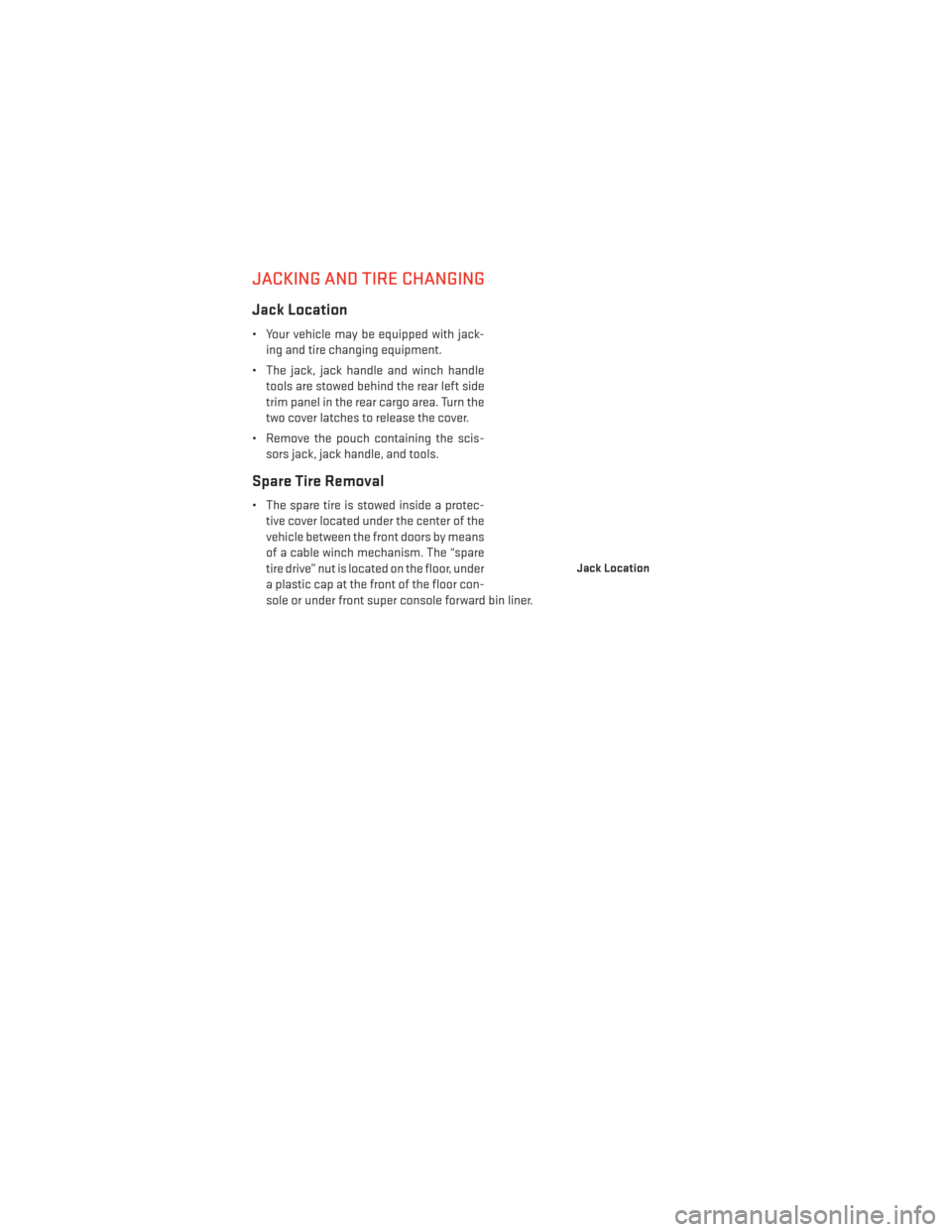
Jack Location
• Your vehicle may be equipped with jack-ing and tire changing equipment.
• The jack, jack handle and winch handle tools are stowed behind the rear left side
trim panel in the rear cargo area. Turn the
two cover latches to release the cover.
• Remove the pouch containing the scis- sors jack, jack handle, and tools.
Spare Tire Removal
• The spare tire is stowed inside a protec-tive cover located under the center of the
vehicle between the front doors by means
of a cable winch mechanism. The “spare
tire drive” nut is located on the floor, under
a plastic cap at the front of the floor con-
sole or under front super console forward bin liner.
Jack Location
WHAT TO DO IN EMERGENCIES
107
Page 114 of 156
Preparations For Jacking
1. Park the vehicle on a firm, level surface. Avoid ice or slippery areas.
2. Turn on the Hazard Warning flasher.
3. Set the parking brake.
4. Place the shift lever into PARK.
5. Turn OFF the ignition.
NOTE:
Passengers should not remain in the vehicle
when the vehicle is being jacked.
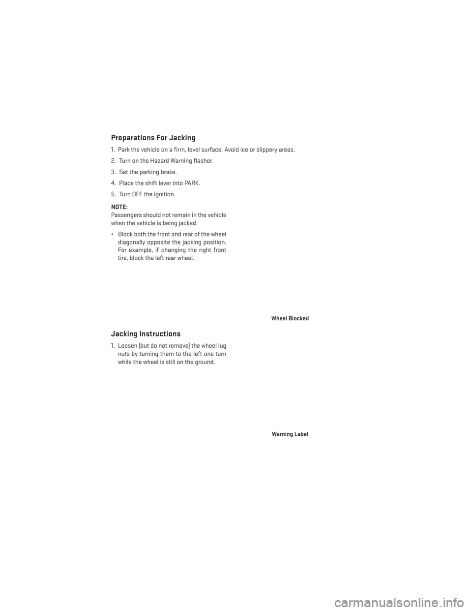
• Block both the front and rear of the wheeldiagonally opposite the jacking position.
For example, if changing the right front
tire, block the left rear wheel.
Jacking Instructions
1. Loosen (but do not remove) the wheel lug
nuts by turning them to the left one turn
while the wheel is still on the ground.
Wheel Blocked
Warning Label
WHAT TO DO IN EMERGENCIES
112
Page 115 of 156
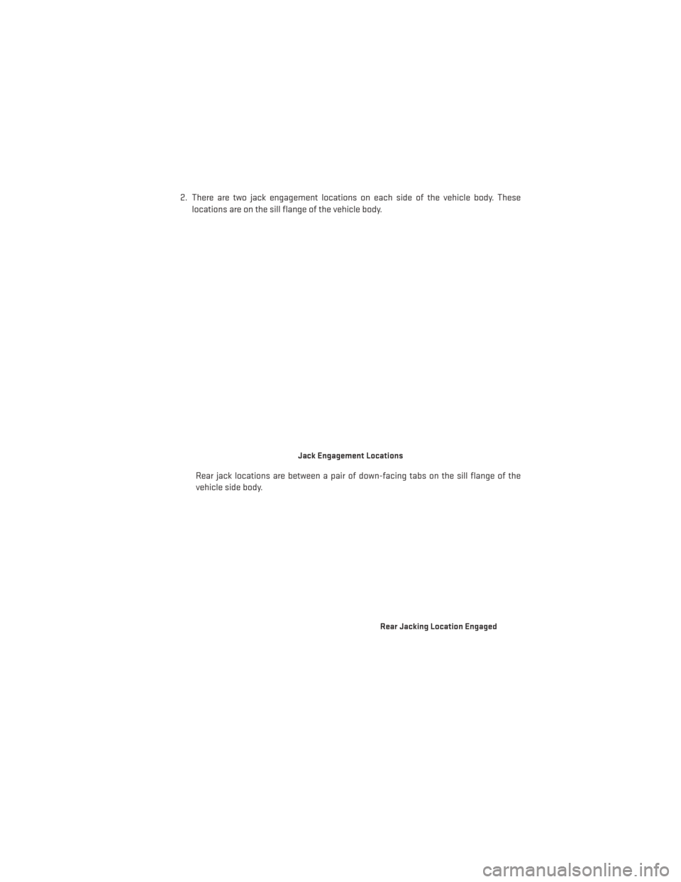
2. There are two jack engagement locations on each side of the vehicle body. Theselocations are on the sill flange of the vehicle body.
Rear jack locations are between a pair of down-facing tabs on the sill flange of the
vehicle side body.
Jack Engagement Locations
Rear Jacking Location Engaged
WHAT TO DO IN EMERGENCIES
113
Page 116 of 156
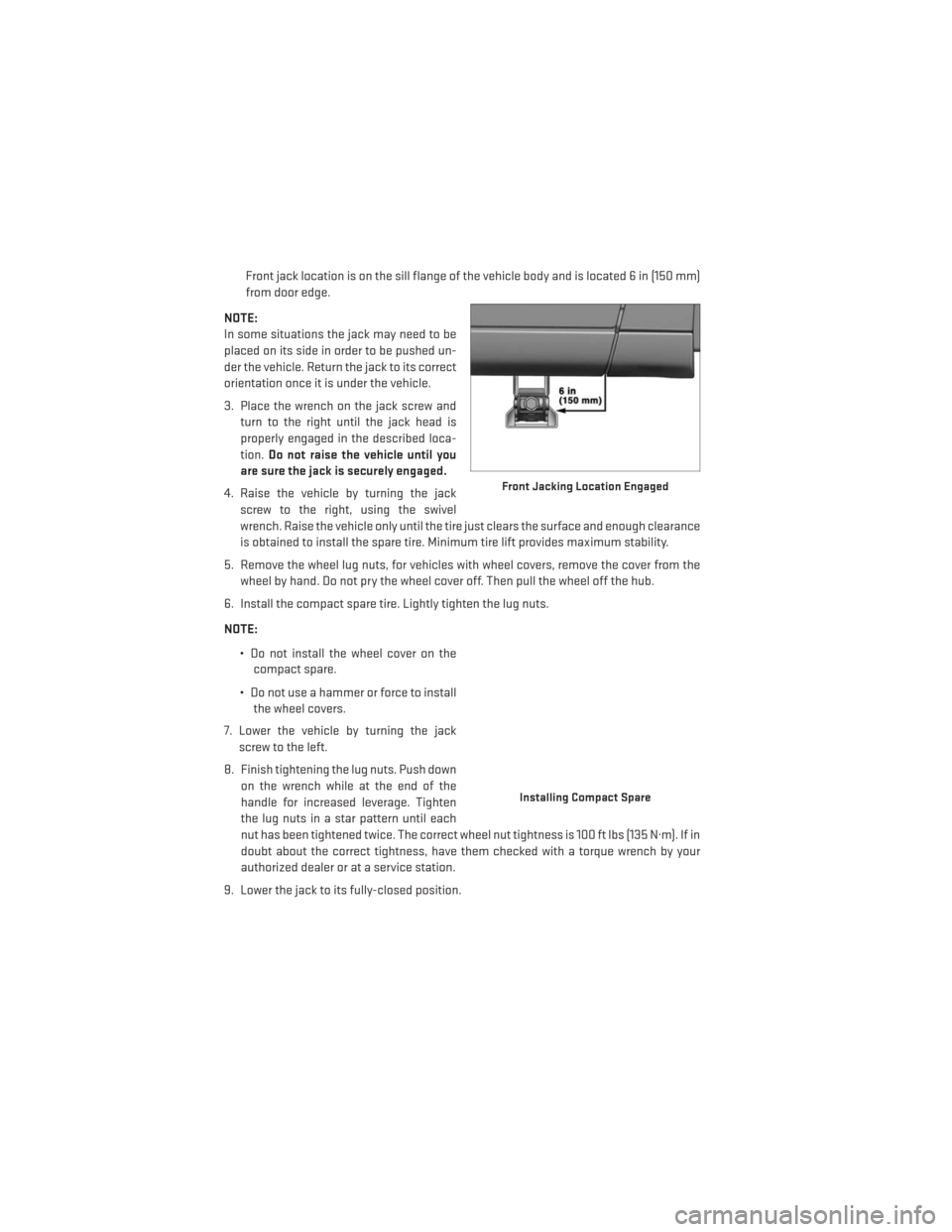
Front jack location is on the sill flange of the vehicle body and is located 6 in (150 mm)
from door edge.
NOTE:
In some situations the jack may need to be
placed on its side in order to be pushed un-
der the vehicle. Return the jack to its correct
orientation once it is under the vehicle.
3. Place the wrench on the jack screw and turn to the right until the jack head is
properly engaged in the described loca-
tion. Do not raise the vehicle until you
are sure the jack is securely engaged.
4. Raise the vehicle by turning the jack screw to the right, using the swivel
wrench. Raise the vehicle only until the tire just clears the surface and enough clearance
is obtained to install the spare tire. Minimum tire lift provides maximum stability.
5. Remove the wheel lug nuts, for vehicles with wheel covers, remove the cover from the wheel by hand. Do not pry the wheel cover off. Then pull the wheel off the hub.
6. Install the compact spare tire. Lightly tighten the lug nuts.
NOTE:
• Do not install the wheel cover on thecompact spare.
• Do not use a hammer or force to install the wheel covers.
7. Lower the vehicle by turning the jack screw to the left.
8. Finish tightening the lug nuts. Push down on the wrench while at the end of the
handle for increased leverage. Tighten
the lug nuts in a star pattern until each
nut has been tightened twice. The correct wheel nut tightness is 100 ft lbs (135 N·m). If in
doubt about the correct tightness, have them checked with a torque wrench by your
authorized dealer or at a service station.
9. Lower the jack to its fully-closed position.
Front Jacking Location Engaged
Installing Compact Spare
WHAT TO DO IN EMERGENCIES
114
Page 119 of 156
Vehicles Without Wheel Covers
1. Mount the road tire on the axle.
2. Install the remaining lug nuts with the cone shaped end of the nut toward the wheel.Lightly tighten the lug nuts.
3. Lower the vehicle to the ground by turning the jack handle counterclockwise.
4. Finish tightening the lug nuts. Push down on the wrench while at the end of the handle for increased leverage. Tighten the lug nuts in a star pattern until each nut has been
tightened twice. The correct tightness of each lug nut is 100 ft/lbs (135 N·m). If in doubt
about the correct tightness, have them checked with a torque wrench by your authorized
dealer or service station.
5. After 25 miles (40 km) check the lug nut torque with a torque wrench to ensure that all lug nuts are properly seated against the wheel.
CAUTION!
• The winch mechanism is designed for use with the winch T-handle only. Use of air wrench or other power tools is not recommended and can damage the winch.
• Do not attempt to raise the vehicle by jacking on locations other than those indicated
in the Jacking Instructions for this vehicle.
• Be sure to mount the spare tire with the valve stem facing outward. The vehicle could
be damaged if the spare tire is mounted incorrectly.
• The compact spare tire/cover assembly must be used when the compact spare tire is
stored. Failure to use this cover could drastically reduce the life of the compact spare
tire.
• The winch mechanism is designed specifically to stow a compact spare tire only. Do
not attempt to use the winch to stow the full size flat tire, or any other full-size tire.
Vehicle damage may result.
WHAT TO DO IN EMERGENCIES
117
Page 145 of 156
Adjustable Pedals.............27
Airbag...................11
Airbag Light ...............98
Alarm Arm The System ...........10
Disarm The System ..........10
Vehicle Security Alarm ........10
Alarm (Security Alarm) ..........10
Anti-Lock Warning Light .........98
Assistance Towing ............95
Audio Jack ............47, 50, 55
Audio Settings ............46,49
Audio Systems (Radio) ..........46
Automatic Headlights ...........31
Automatic Temperature Control (ATC) . .37
Automatic Transmission Fluid Type ..............127
Auxiliary Audio/Video Input Jacks ....83
AxleFluid ................127
Back-UpCamera.............39
Blind Spot Monitoring ..........39
BrakeFluid................127
Break-In Recommendations, New Vehicle ..............28
BulbReplacement............137
Calibration, Compass...........84
Cargo Compartment Luggage Carrier ...........92
CD (Compact Disc) Player .......47, 50
Change Oil Indicator ...........99
Changing A Flat Tire ...........107
Charging System Light ..........98
Child Restraints CarSeat................12
Child Restraints ............12
Child Seat Installation .........14
Installing Child Restraints Using The
Vehicle Seat Belt ...........14
Lower Anchors And Tethers For
Children................12
Clock Setting ...........46,48,51
Cluster Warning/Indicator Lights Anti-Lock Brake (ABS) Light .....98
Charging System Light ........98
Electronic Throttle Control (ETC)
Indicator Light ............98 Malfunction Indicator Light (MIL) . . .97
Oil Pressure Warning Light
......98
Tire Pressure Monitoring System
(TPMS) Light .............95
Compass Calibration ...........84
Cooling System Coolant Capacity ..........127
Cruise Control (Speed Control) ......32
Cruise Light ................32
Customer Assistance ..........138
Defects, Reporting ............139
DimmerControl..............31
Dimmer Switch, Headlight ........31
Disabled Vehicle Towing .........95
Disarming, Security System .......10
Driver Cockpit ...............4
Economy (Fuel) Mode ...........34
Electronics Your Vehicle's Sound System . .44, 45
Electronic Speed Control (Cruise Control) ............
32
Electronic Stability Control (ESC) .....95
Electronic Stability Control (ESC) OFF Indicator ................97
Electronic Throttle Control Warning Light .............98
Electronic Vehicle Information Center (EVIC) ...........84,85
Emergency, In Case of Brake Warning Light .........97
Freeing Vehicle When Stuck . . . .122
Jacking .............107,112
Overheating .............99
Towing ................95
Engine Break-In Recommendations .....28
Compartment ............126
Oil Selection .............127
Overheating .............99
EventDataRecorder.......... .123
Exterior Lights ..............137
Flash-To-Pass ..............30
Fluid Capacities .............127
Fluids ...................127
FogLights.................31
INDEX
143
Page 147 of 156
Lift Gate................8
Outlet (Auxiliary Electrical Outlet) . .90
Seats .................16
Steering ...............127
Preparation for Jacking .........112
Programmable Electronic Features . . .85
Radio Operation ............47, 49
Rain Sensitive Wiper System .......29
RearCamera...............39
RearCrossPath .............39
Rear Heated Seats ............24
Rear ParkSense System .........39
Recreational Towing ...........93
Remote Keyless Entry (RKE) Arm The Alarm ............10
Disarm The Alarm ...........10
LockTheDoors ............8
Remote Keyless Entry (RKE) ......8
UnlockTheDoors ...........8
Remote Starting System ..........9
Replacement Bulbs ...........137
Reporting Safety Defects ........139
Rocking Vehicle When Stuck ......122
Roof Rack (Luggage Rack) ........92
Satellite Radio (Uconnect® studios) ........48,50
Schedule, Maintenance .........128
Seat Belt Automatic Locking Retractor (ALR) . .10
Child Restraints ..........10,12
Energy Management Feature .....10
Lap/ShoulderBelts..........10
Seat Belt Pretensioner ........10
SeatBeltReminder..........10
Seats..................16,17 Adjustment ..............17
Fold in Floor (Stow `n Go) .......19
Heated ................24
Lumbar Support ...........16
Manual.................17
Memory ................17
Power .................16
Stow`nGo(FoldinFloor) .......19
Security Alarm Arm The System ...........10 Disarm The System
..........10
Security Alarm ............10
Shift Lever Override ...........121
Signals, Turn ...............29
Sirius Satellite Radio ...........71
SIRIUSTravelLink.............71
SpareTire ................107
Spark Plugs ...............127
Speed Control Accel/Decel .............32
Cancel ................33
Resume ...............33
Set ..................32
Starting Remote ................9
Steering Tilt Column ..............26
Wheel, Heated ............25
Steering Wheel Audio Controls ......75
Stow `n Go (Fold in Floor) Seats ......19
Stuck, Freeing ..............122
SunRoof .................41
Supplemental Restraint System - Airbag .................11
Tilt Steering Column ...........26
TIREFIT...............100,101
Tires Air Pressure .............136
Changing ..............
107
Jacking .............107,112
SpareTire ..............107
Touchscreen Radio Cleaning Your Touchscreen
Radio ...............57,66
Towing ..................93 Disabled Vehicle ...........121
Recreational .............93
Trailer Towing Trailer and Tongue Weight ......93
Trailer Weight ...............93
Transmission Fluid .................127
TurnSignals ...............29
Uconnect® Voice Command .......79
INDEX
145