water pump DODGE GRAND CARAVAN 2015 5.G User Guide
[x] Cancel search | Manufacturer: DODGE, Model Year: 2015, Model line: GRAND CARAVAN, Model: DODGE GRAND CARAVAN 2015 5.GPages: 164, PDF Size: 22.27 MB
Page 106 of 164

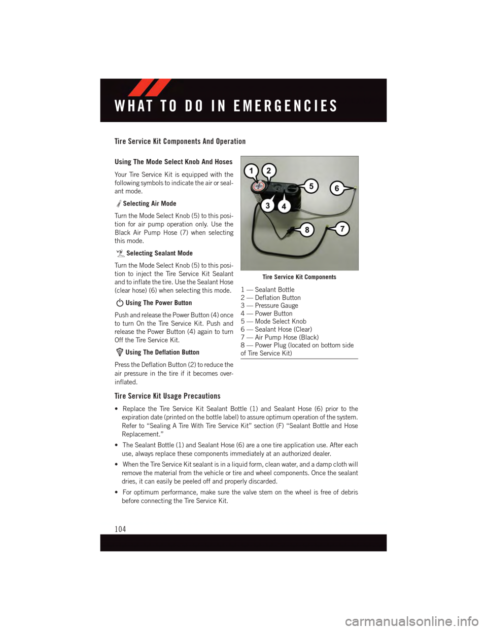
Tire Service Kit Components And Operation
Using The Mode Select Knob And Hoses
Yo u r Ti r e S e r v i c e K i t i s e q u i p p e d w i t h t h e
following symbols to indicate the air or seal-
ant mode.
Selecting Air Mode
Tu r n t h e M o d e S e l e c t K n o b ( 5 ) t o t h i s p o s i -
tion for air pump operation only. Use the
Black Air Pump Hose (7) when selecting
this mode.
Selecting Sealant Mode
Tu r n t h e M o d e S e l e c t K n o b ( 5 ) t o t h i s p o s i -
tion to inject the Tire Service Kit Sealant
and to inflate the tire. Use the Sealant Hose
(clear hose) (6) when selecting this mode.
Using The Power Button
Push and release the Power Button (4) once
to turn On the Tire Service Kit. Push and
release the Power Button (4) again to turn
Off the Tire Service Kit.
Using The Deflation Button
Press the Deflation Button (2) to reduce the
air pressure in the tire if it becomes over-
inflated.
Tire Service Kit Usage Precautions
•ReplacetheTireServiceKitSealantBottle(1)andSealantHose(6)priortothe
expiration date (printed on the bottle label) to assure optimum operation of the system.
Refer to “Sealing A Tire With Tire Service Kit” section (F) “Sealant Bottle and Hose
Replacement.”
•TheSealantBottle(1)andSealantHose(6)areaonetireapplicationuse.Aftereach
use, always replace these components immediately at an authorized dealer.
•WhentheTireServiceKitsealantisinaliquidform,cleanwater,andadampclothwill
remove the material from the vehicle or tire and wheel components. Once the sealant
dries, it can easily be peeled off and properly discarded.
•Foroptimumperformance,makesurethevalvestemonthewheelisfreeofdebris
before connecting the Tire Service Kit.
Tire Service Kit Components
1—SealantBottle2—DeflationButton3—PressureGauge4—PowerButton5—ModeSelectKnob6—SealantHose(Clear)7—AirPumpHose(Black)8—PowerPlug(locatedonbottomsideof Tire Service Kit)
WHAT TO DO IN EMERGENCIES
104
Page 140 of 164

Totally Integrated Power Module (Fuses)
The Totally Integrated Power Module is located in the engine compartment near the
battery. Refer to the applicable “Engine Compartment” illustration in this section. This
center contains cartridge fuses and mini-fuses. A label that identifies each component
may be printed or embossed on the inside of the cover.
CAUTION!
•WheninstallingtheTotallyIntegratedPowerModulecover,itisimportanttoensure
the cover is properly positioned and fully latched. Failure to do so may allow water
to get into the Integrated Power Module, and possibly result in a electrical system
failure.
•Whenreplacingablownfuse,itisimportanttouseonlyafusehavingthecorrect
amperage rating. The use of a fuse with a rating other than indicated may result in
adangerouselectricalsystemoverload.Ifaproperlyratedfusecontinuestoblow,
it indicates a problem in the circuit that must be corrected.
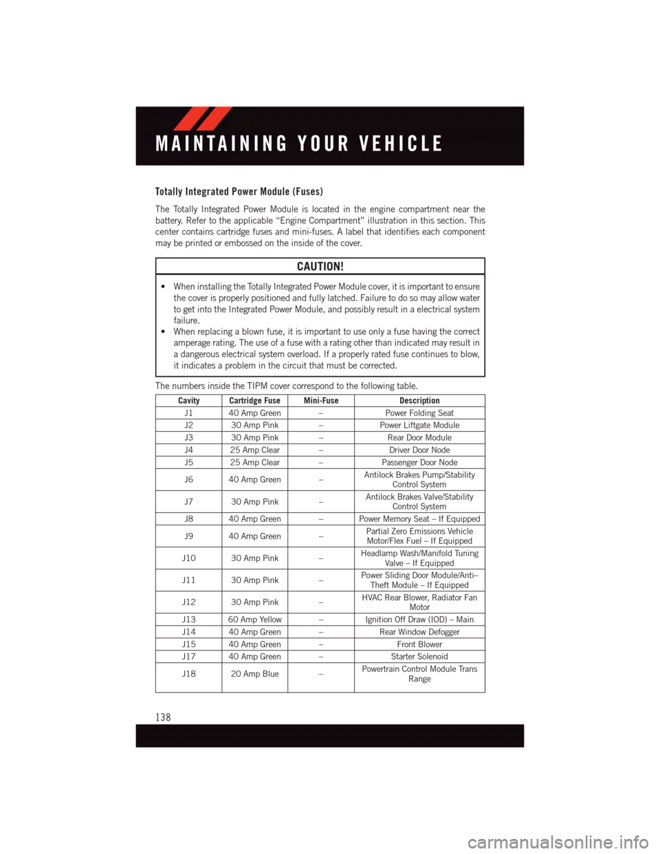
The numbers inside the TIPM cover correspond to the following table.
Cavity Cartridge Fuse Mini-FuseDescription
J1 40 Amp Green –Power Folding Seat
J2 30 Amp Pink –Power Liftgate Module
J3 30 Amp Pink –Rear Door Module
J4 25 Amp Clear –Driver Door Node
J5 25 Amp Clear –Passenger Door Node
J6 40 Amp Green –Antilock Brakes Pump/StabilityControl System
J7 30 Amp Pink –Antilock Brakes Valve/StabilityControl System
J8 40 Amp Green – Power Memory Seat – If Equipped
J9 40 Amp Green –Partial Zero Emissions VehicleMotor/Flex Fuel – If Equipped
J10 30 Amp Pink –Headlamp Wash/Manifold TuningValve – If Equipped
J11 30 Amp Pink –Power Sliding Door Module/Anti–Theft Module – If Equipped
J12 30 Amp Pink –HVAC Rear Blower, Radiator FanMotor
J13 60 Amp Yellow – Ignition Off Draw (IOD) – Main
J14 40 Amp Green –Rear Window Defogger
J15 40 Amp Green –Front Blower
J17 40 Amp Green –Starter Solenoid
J18 20 Amp Blue –Powertrain Control Module TransRange
MAINTAINING YOUR VEHICLE
138