lug DODGE GRAND CARAVAN 2016 5.G Owner's Manual
[x] Cancel search | Manufacturer: DODGE, Model Year: 2016, Model line: GRAND CARAVAN, Model: DODGE GRAND CARAVAN 2016 5.GPages: 707, PDF Size: 5.24 MB
Page 470 of 707
ENGINE BLOCK HEATER — IF EQUIPPED
The engine block heater warms the engine, and permits
quicker starts in cold weather. Connect the cord to a
standard 110-115 Volt AC electrical outlet with a
grounded, three-wire extension cord.
The engine block heater must be plugged in at least one
hour to have an adequate warming effect on the engine.
The engine block heater cord is routed under the hood on
the driver’s side of the vehicle. It has a removable cap
that is located on the driver side of the Integrated Power
Module.
WARNING!
Remember to disconnect the engine block heater
cord before driving. Damage to the 110-115 Volt
electrical cord could cause electrocution.
AUTOMATIC TRANSMISSION
CAUTION!
Damage to the transmission may occur if the follow-
ing precautions are not observed:
•Shift into or out of PARK or REVERSE only after
the vehicle has come to a complete stop.
• Do not shift between PARK, REVERSE, NEU-
TRAL, or DRIVE when the engine is above idle
speed.
• Before shifting into any gear, make sure your foot
is firmly pressing the brake pedal.
NOTE: You must press and hold the brake pedal while
shifting out of PARK.
468 STARTING AND OPERATING
Page 511 of 707
To determine the maximum loading conditions of your
vehicle, locate the statement “The combined weight of
occupants and cargo should never exceed XXX lbs or
XXX kg” on the Tire and Loading Information placard.
The combined weight of occupants, cargo/luggage and
trailer tongue weight (if applicable) should never exceed
the weight referenced here.
Steps For Determining Correct Load Limit
1. Locate the statement “The combined weight of occu-pants and cargo should never exceed XXX lbs or
XXX kg” on your vehicle’s placard.
2. Determine the combined weight of the driver and passengers that will be riding in your vehicle.
3. Subtract the combined weight of the driver and pas- sengers from XXX lbs or XXX kg. 4. The resulting figure equals the available amount of
cargo and luggage load capacity. For example, if
“XXX” amount equals 1,400 lbs (635 kg) and there will
be five 150 lb (68 kg) passengers in your vehicle, the
amount of available cargo and luggage load capacity
is 650 lbs (295 kg) (since 5 x 150 lbs (68 kg) = 750 lbs
(340 kg), and 1400 lbs (635 kg) – 750 lbs (340 kg) =
650 lbs [295 kg]).
5. Determine the combined weight of luggage and cargo being loaded on the vehicle. That weight may not
safely exceed the available cargo and luggage load
capacity calculated in step 4.
5
STARTING AND OPERATING 509
Page 512 of 707
NOTE:
•If your vehicle will be towing a trailer, load from your
trailer will be transferred to your vehicle. The follow-
ing table shows examples on how to calculate total
load, cargo/luggage, and towing capacities of your
vehicle with varying seating configurations and num-
ber and size of occupants. This table is for illustration
purposes only and may not be accurate for the seating
and load carry capacity of your vehicle.
• For the following example, the combined weight of
occupants and cargo should never exceed 865 lbs
(392 kg).
510 STARTING AND OPERATING
Page 515 of 707
WARNING!(Continued)
•Unequal tire pressures from one side of the vehicle
to the other can cause the vehicle to drift to the
right or left.
• Always drive with each tire inflated to the recom-
mended cold tire inflation pressure.
Both under-inflation and over-inflation affect the stability
of the vehicle and can produce a feeling of sluggish
response or over responsiveness in the steering.
NOTE:
• Unequal tire pressures from side to side may cause
erratic and unpredictable steering response.
• Unequal tire pressure from side to side may cause the
vehicle to drift left or right.
Fuel Economy
Underinflated tires will increase tire rolling resistance
resulting in higher fuel consumption.
Tread Wear
Improper cold tire inflation pressures can cause abnor-
mal wear patterns and reduced tread life, resulting in the
need for earlier tire replacement.
Ride Comfort And Vehicle Stability
Proper tire inflation contributes to a comfortable ride.
Over-inflation produces a jarring and uncomfortable
ride.
Tire Inflation Pressures
The proper cold tire inflation pressure is listed on the
driver’s side B-Pillar or rear edge of the driver’s side
door.
5
STARTING AND OPERATING 513
Page 540 of 707
MMT In Gasoline
Methylcyclopentadienyl Manganese Tricarbonyl (MMT)
is a manganese-containing metallic additive that is
blended into some gasoline to increase octane. Gasoline
blended with MMT provides no performance advantage
beyond gasoline of the same octane number without
MMT. Gasoline blended with MMT reduces spark plug
life and reduces emissions system performance in some
vehicles. The manufacturer recommends that gasoline
without MMT be used in your vehicle. The MMT content
of gasoline may not be indicated on the gasoline pump,
therefore, you should ask your gasoline retailer whether
the gasoline contains MMT. MMT is prohibited in Federal
and California reformulated gasoline.
Materials Added To Fuel
Besides using unleaded gasoline with the proper octane
rating, gasolines that contain detergents, corrosion and
stability additives are recommended. Using gasolines
that have these additives will help improve fuel
economy, reduce emissions, and maintain vehicle perfor-
mance. Designated TOP TIER Detergent Gasoline con-
tains a higher level of detergents to further aide in
minimizing engine and fuel system deposits. When avail-
able the usage of Top Tier Detergent gasoline is recom-
mended. Visit www.toptiergas.com for a list of TOP TIER
Detergent Gasoline Retailers.
Indiscriminate use of fuel system cleaning agents should
be avoided. Many of these materials intended for gum
and varnish removal may contain active solvents or
similar ingredients. These can harm fuel system gasket
and diaphragm materials.
538 STARTING AND OPERATING
Page 552 of 707
WARNING!
It is important that you do not exceed the maximum
front or rear GAWR. A dangerous driving condition
can result if either rating is exceeded. You could lose
control of the vehicle and have a collision.
Tongue Weight (TW)
The tongue weight is the downward force exerted on the
hitch ball by the trailer. The recommended tongue weight
is 10% to 15% of the vehicle’s GTW for a conventional
hitch. You must consider this as part of the load on your
vehicle.
Frontal Area
The frontal area is the maximum height multiplied by the
maximum width of the front of a trailer.
Trailer Sway Control
The trailer sway control can be a mechanical telescoping
link that can be installed between the hitch receiver and
the trailer tongue that typically provides adjustable fric-
tion associated with the telescoping motion to dampen
any unwanted trailer swaying motions while traveling.
If equipped, the electronic Trailer Sway Control (TSC)
recognizes a swaying trailer and automatically applies
individual wheel brakes and/or reduces engine power to
attempt to eliminate the trailer sway.
Weight-Carrying Hitch
A weight-carrying hitch supports the trailer tongue
weight, just as if it were luggage located at a hitch ball or
some other connecting point of the vehicle. These kinds
of hitches are the most popular on the market today and
they are commonly used to tow small and medium sized
trailers.
550 STARTING AND OPERATING
Page 555 of 707
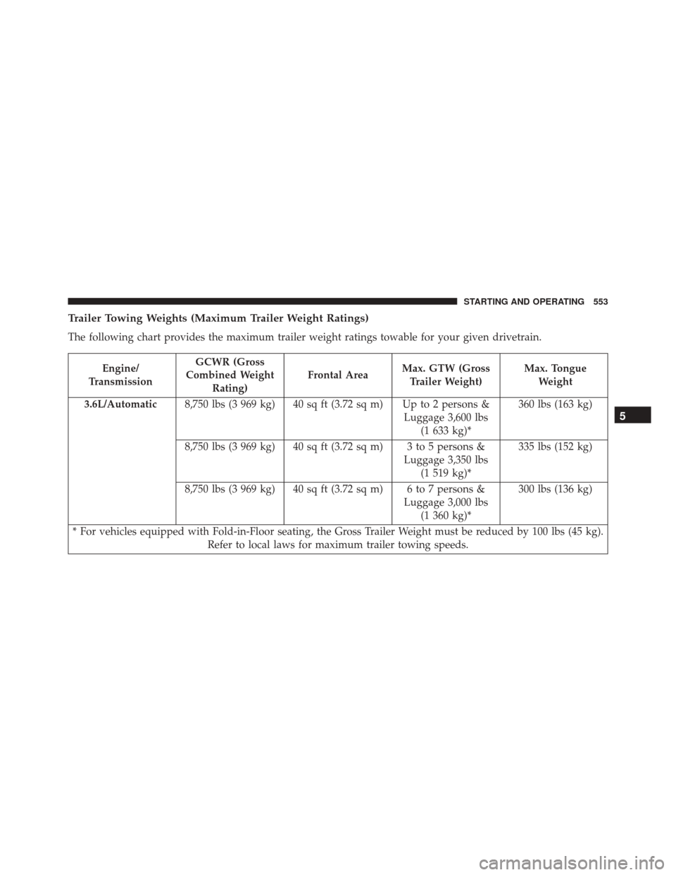
Trailer Towing Weights (Maximum Trailer Weight Ratings)
The following chart provides the maximum trailer weight ratings towable for your given drivetrain.
Engine/
Transmission GCWR (Gross
Combined Weight Rating) Frontal Area
Max. GTW (Gross
Trailer Weight) Max. Tongue
Weight
3.6L/Automatic 8,750 lbs (3 969 kg) 40 sq ft (3.72 sq m) Up to 2 persons &
Luggage 3,600 lbs(1 633 kg)* 360 lbs (163 kg)
8,750 lbs (3 969 kg) 40 sq ft (3.72 sq m) 3 to 5 persons & Luggage 3,350 lbs(1 519 kg)* 335 lbs (152 kg)
8,750 lbs (3 969 kg) 40 sq ft (3.72 sq m) 6 to 7 persons & Luggage 3,000 lbs(1 360 kg)* 300 lbs (136 kg)
* For vehicles equipped with Fold-in-Floor seating, the Gross Trailer Weight must be reduced by 100 lbs (45 kg). Refer to local laws for maximum trailer towing speeds.
5
STARTING AND OPERATING 553
Page 572 of 707
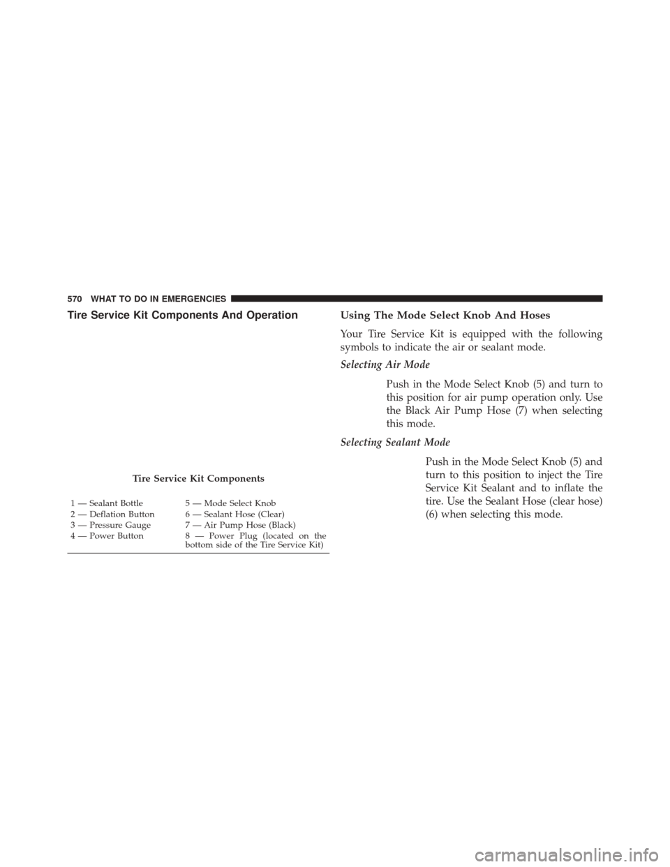
Tire Service Kit Components And OperationUsing The Mode Select Knob And Hoses
Your Tire Service Kit is equipped with the following
symbols to indicate the air or sealant mode.
Selecting Air Mode
Push in the Mode Select Knob (5) and turn to
this position for air pump operation only. Use
the Black Air Pump Hose (7) when selecting
this mode.
Selecting Sealant Mode
Push in the Mode Select Knob (5) and
turn to this position to inject the Tire
Service Kit Sealant and to inflate the
tire. Use the Sealant Hose (clear hose)
(6) when selecting this mode.
Tire Service Kit Components
1 — Sealant Bottle 5 — Mode Select Knob
2 — Deflation Button 6 — Sealant Hose (Clear)
3 — Pressure Gauge 7 — Air Pump Hose (Black)
4 — Power Button 8 — Power Plug (located on the bottom side of the Tire Service Kit)
570 WHAT TO DO IN EMERGENCIES
Page 576 of 707
2. Verify that the valve stem (on the wheel with thedeflated tire) is in a position that is near to the ground.
This will allow the Tire Service Kit Hoses (6) and (7) to
reach the valve stem and keep the Tire Service Kit flat
on the ground. This will provide the best positioning
of the kit when injecting the sealant into the deflated
tire and running the air pump. Move the vehicle as
necessary to place the valve stem in this position
before proceeding.
3. Place the transmission in PARK (auto transmission) or in Gear (manual transmission) and place the ignition
in the OFF position.
4. Set the parking brake.(B) Setting Up To Use Tire Service Kit:
1. Push in the Mode Select Knob (5) and turn to the Sealant Mode position.
2. Uncoil the Sealant Hose (6) and then remove the cap from the fitting at the end of the hose.
3. Place the Tire Service Kit flat on the ground next to the deflated tire.
4. Remove the cap from the valve stem and then screw the fitting at the end of the Sealant Hose (6) onto the
valve stem.
5. Uncoil the Power Plug (8) and insert the plug into the vehicle’s 12 Volt power outlet.
NOTE: Do not remove foreign objects (e.g., screws or
nails) from the tire.
574 WHAT TO DO IN EMERGENCIES
Page 577 of 707
(C) Injecting Tire Service Kit Sealant Into The
Deflated Tire:
•Always start the engine before turning ON the Tire
Service Kit.
NOTE: Manual transmission vehicles must have the
parking brake engaged and the shift lever in NEUTRAL.
• After pushing the Power Button (4), the sealant (white
fluid) will flow from the Sealant Bottle (1) through the
Sealant Hose (6) and into the tire.
NOTE: Sealant may leak out through the puncture in the
tire.
If the sealant (white fluid) does not flow within0–10
seconds through the Sealant Hose (6):
1. Push the Power Button (4) to turn Off the Tire Service Kit. Disconnect the Sealant Hose (6) from the valve
stem. Make sure the valve stem is free of debris. Reconnect the Sealant Hose (6) to the valve stem.
Check that the Mode Select Knob (5) is in the Sealant
Mode position and not Air Mode. Push the Power
Button (4) to turn On the Tire Service Kit.
2. Connect the Power Plug (8) to a different 12 Volt power outlet in your vehicle or another vehicle, if
available. Make sure the engine is running before
turning ON the Tire Service Kit.
3. The Sealant Bottle (1) may be empty due to previous use. Call for assistance.
NOTE: If the Mode Select Knob (5) is on Air Mode and
the pump is operating, air will dispense from the Air
Pump Hose (7) only, not the Sealant Hose (6).
6
WHAT TO DO IN EMERGENCIES 575