fuel pump DODGE GRAND CARAVAN 2016 5.G Owners Manual
[x] Cancel search | Manufacturer: DODGE, Model Year: 2016, Model line: GRAND CARAVAN, Model: DODGE GRAND CARAVAN 2016 5.GPages: 707, PDF Size: 5.24 MB
Page 307 of 707
1. Tachometer•This gauge measures engine revolutions per minute
(RPM x 1000). Before the pointer reaches the red area,
ease up on the accelerator to prevent engine damage.
2. Speedometer •Indicates vehicle speed.
3. Fuel Gauge •The pointer shows the level of fuel in the fuel tank
when the ignition switch is in the ON/RUN position
The fuel pump symbol points to the side of the
vehicle where the fuel door is located.
4. Odometer Display/Electronic Vehicle Infor-mation Center (EVIC) — If Equipped
Odometer Display / Trip Odometer Display The odom-
eter display shows the total distance the vehicle has been
driven. U.S. Federal regulations require that upon transfer of
vehicle ownership, the seller certify to the purchaser the
correct mileage that the vehicle has been driven. If your
odometer needs to be repaired or serviced, the repair
technician should leave the odometer reading the same
as it was before the repair or service. If s/he cannot do so,
then the odometer must be set at zero, and a sticker must
be placed in the door jamb stating what the mileage was
before the repair or service. It is a good idea for you to
make a record of the odometer reading before the repair/
service, so that you can be sure that it is properly reset, or
that the door jamb sticker is accurate if the odometer
must be reset at zero.
This also displays Trip A and Trip B, DTE, MPG or
L/100km, OAT (Outside Air Temperature) information to
Base Cluster, use STEP and RESET button (on steering
wheel) to access or reset the display.
4
UNDERSTANDING YOUR INSTRUMENT PANEL 305
Page 315 of 707
•The pointer shows the level of fuel in the fuel tank
when the ignition switch is in the ON/RUN position
The fuel pump symbol points to the side of the
vehicle where the fuel door is located.
5. Temperature Gauge
• The temperature gauge shows engine coolant tem-
perature. Any reading within the normal range indi-
cates that the engine cooling system is operating
satisfactorily.
• The gauge pointer will likely indicate a higher tem-
perature when driving in hot weather or up moun-
tain grades. It should not be allowed to exceed the
upper limits of the normal operating range.CAUTION!
Driving with a hot engine cooling system could
damage your vehicle. If the temperature gauge reads
“H” pull over and stop the vehicle. Idle the vehicle
with the air conditioner turned off until the pointer
drops back into the normal range. If the pointer
remains on the “H” and you hear continuous chimes,
turn the engine off immediately and call an autho-
rized dealer for service.
4
UNDERSTANDING YOUR INSTRUMENT PANEL 313
Page 539 of 707
The use of reformulated gasoline is recommended. Prop-
erly blended reformulated gasoline will provide im-
proved performance and durability of engine and fuel
system components.
Gasoline/Oxygenate Blends
Some fuel suppliers blend unleaded gasoline with oxy-
genates such as ethanol.
CAUTION!
DO NOT use gasoline containing methanol or gaso-
line containing more than 15% ethanol (E-15). Use of
these blends may result in starting and drivability
problems, damage critical fuel system components,
cause emissions to exceed the applicable standard,
and/or cause the “Malfunction Indicator Light” to
illuminate. Please observe pump labels as they
should clearly communicate if a fuel contains greater
than 15% ethanol (E-15).
Problems that result from using gasoline containing more
than 15% ethanol (E-15) or gasoline containing methanol are
not the responsibility of the manufacturer and may void or
not be covered under New Vehicle Limited Warranty.
E-85 Usage In Non-Flex Fuel Vehicles
Non-Flex Fuel Vehicles (FFV) are compatible with gaso-
line containing up to 15% ethanol (E-15). Gasoline with
higher ethanol content may void the New Vehicle Lim-
ited Warranty.
If a Non-FFV vehicle is inadvertently fueled with E-85
fuel, the engine will have some or all of these symptoms:
•Operate in a lean mode.
• OBD II “Malfunction Indicator Light” on.
• Poor engine performance.
• Poor cold start and cold drivability.
• Increased risk for fuel system component corrosion.
5
STARTING AND OPERATING 537
Page 540 of 707
MMT In Gasoline
Methylcyclopentadienyl Manganese Tricarbonyl (MMT)
is a manganese-containing metallic additive that is
blended into some gasoline to increase octane. Gasoline
blended with MMT provides no performance advantage
beyond gasoline of the same octane number without
MMT. Gasoline blended with MMT reduces spark plug
life and reduces emissions system performance in some
vehicles. The manufacturer recommends that gasoline
without MMT be used in your vehicle. The MMT content
of gasoline may not be indicated on the gasoline pump,
therefore, you should ask your gasoline retailer whether
the gasoline contains MMT. MMT is prohibited in Federal
and California reformulated gasoline.
Materials Added To Fuel
Besides using unleaded gasoline with the proper octane
rating, gasolines that contain detergents, corrosion and
stability additives are recommended. Using gasolines
that have these additives will help improve fuel
economy, reduce emissions, and maintain vehicle perfor-
mance. Designated TOP TIER Detergent Gasoline con-
tains a higher level of detergents to further aide in
minimizing engine and fuel system deposits. When avail-
able the usage of Top Tier Detergent gasoline is recom-
mended. Visit www.toptiergas.com for a list of TOP TIER
Detergent Gasoline Retailers.
Indiscriminate use of fuel system cleaning agents should
be avoided. Many of these materials intended for gum
and varnish removal may contain active solvents or
similar ingredients. These can harm fuel system gasket
and diaphragm materials.
538 STARTING AND OPERATING
Page 547 of 707
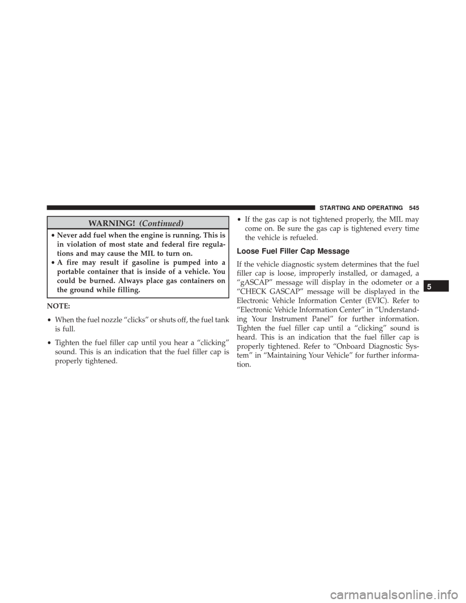
WARNING!(Continued)
•Never add fuel when the engine is running. This is
in violation of most state and federal fire regula-
tions and may cause the MIL to turn on.
• A fire may result if gasoline is pumped into a
portable container that is inside of a vehicle. You
could be burned. Always place gas containers on
the ground while filling.
NOTE:
• When the fuel nozzle “clicks” or shuts off, the fuel tank
is full.
• Tighten the fuel filler cap until you hear a “clicking”
sound. This is an indication that the fuel filler cap is
properly tightened. •
If the gas cap is not tightened properly, the MIL may
come on. Be sure the gas cap is tightened every time
the vehicle is refueled.
Loose Fuel Filler Cap Message
If the vehicle diagnostic system determines that the fuel
filler cap is loose, improperly installed, or damaged, a
“gASCAP” message will display in the odometer or a
“CHECK GASCAP” message will be displayed in the
Electronic Vehicle Information Center (EVIC). Refer to
“Electronic Vehicle Information Center” in “Understand-
ing Your Instrument Panel” for further information.
Tighten the fuel filler cap until a “clicking” sound is
heard. This is an indication that the fuel filler cap is
properly tightened. Refer to “Onboard Diagnostic Sys-
tem” in “Maintaining Your Vehicle” for further informa-
tion.
5
STARTING AND OPERATING 545
Page 651 of 707
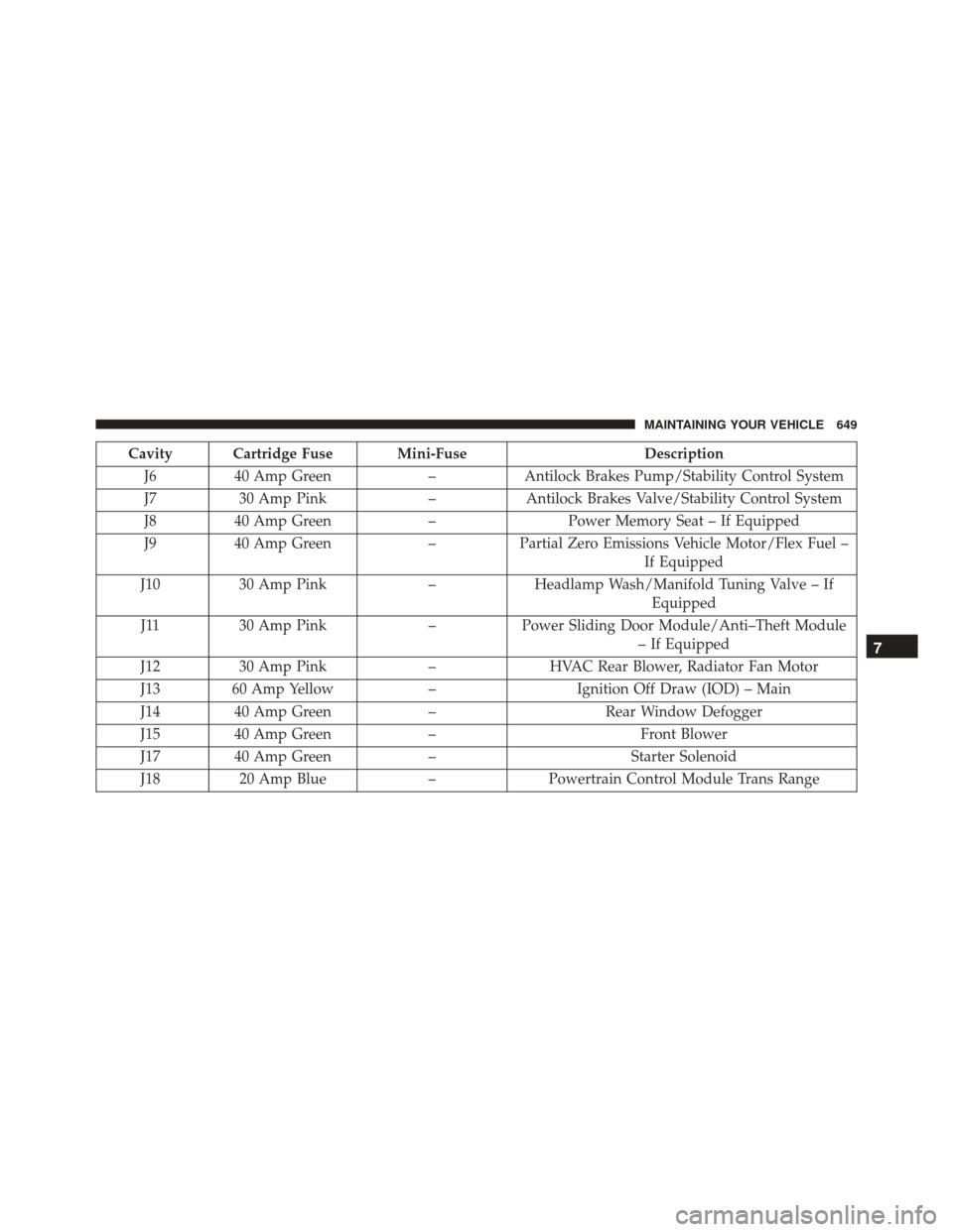
Cavity Cartridge Fuse Mini-FuseDescription
J6 40 Amp Green –Antilock Brakes Pump/Stability Control System
J7 30 Amp Pink –Antilock Brakes Valve/Stability Control System
J8 40 Amp Green –Power Memory Seat – If Equipped
J9 40 Amp Green –Partial Zero Emissions Vehicle Motor/Flex Fuel –
If Equipped
J10 30 Amp Pink –Headlamp Wash/Manifold Tuning Valve – If
Equipped
J11 30 Amp Pink –Power Sliding Door Module/Anti–Theft Module
– If Equipped
J12 30 Amp Pink –HVAC Rear Blower, Radiator Fan Motor
J13 60 Amp Yellow –Ignition Off Draw (IOD) – Main
J14 40 Amp Green –Rear Window Defogger
J15 40 Amp Green – Front Blower
J17 40 Amp Green – Starter Solenoid
J18 20 Amp Blue –Powertrain Control Module Trans Range
7
MAINTAINING YOUR VEHICLE 649
Page 654 of 707
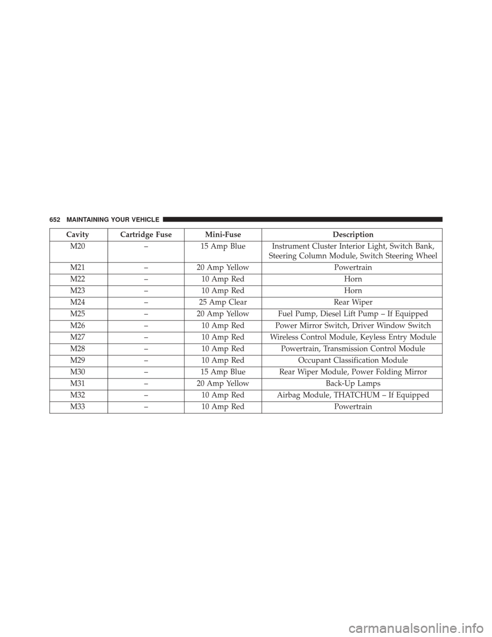
Cavity Cartridge Fuse Mini-FuseDescription
M20 –15 Amp Blue Instrument Cluster Interior Light, Switch Bank,
Steering Column Module, Switch Steering Wheel
M21 –20 Amp Yellow Powertrain
M22 –10 Amp Red Horn
M23 –10 Amp Red Horn
M24 –25 Amp Clear Rear Wiper
M25 –20 Amp Yellow Fuel Pump, Diesel Lift Pump – If Equipped
M26 –10 Amp Red Power Mirror Switch, Driver Window Switch
M27 –10 Amp Red Wireless Control Module, Keyless Entry Module
M28 –10 Amp Red Powertrain, Transmission Control Module
M29 –10 Amp Red Occupant Classification Module
M30 –15 Amp Blue Rear Wiper Module, Power Folding Mirror
M31 –20 Amp Yellow Back-Up Lamps
M32 –10 Amp Red Airbag Module, THATCHUM – If Equipped
M33 –10 Amp Red Powertrain
652 MAINTAINING YOUR VEHICLE
Page 655 of 707
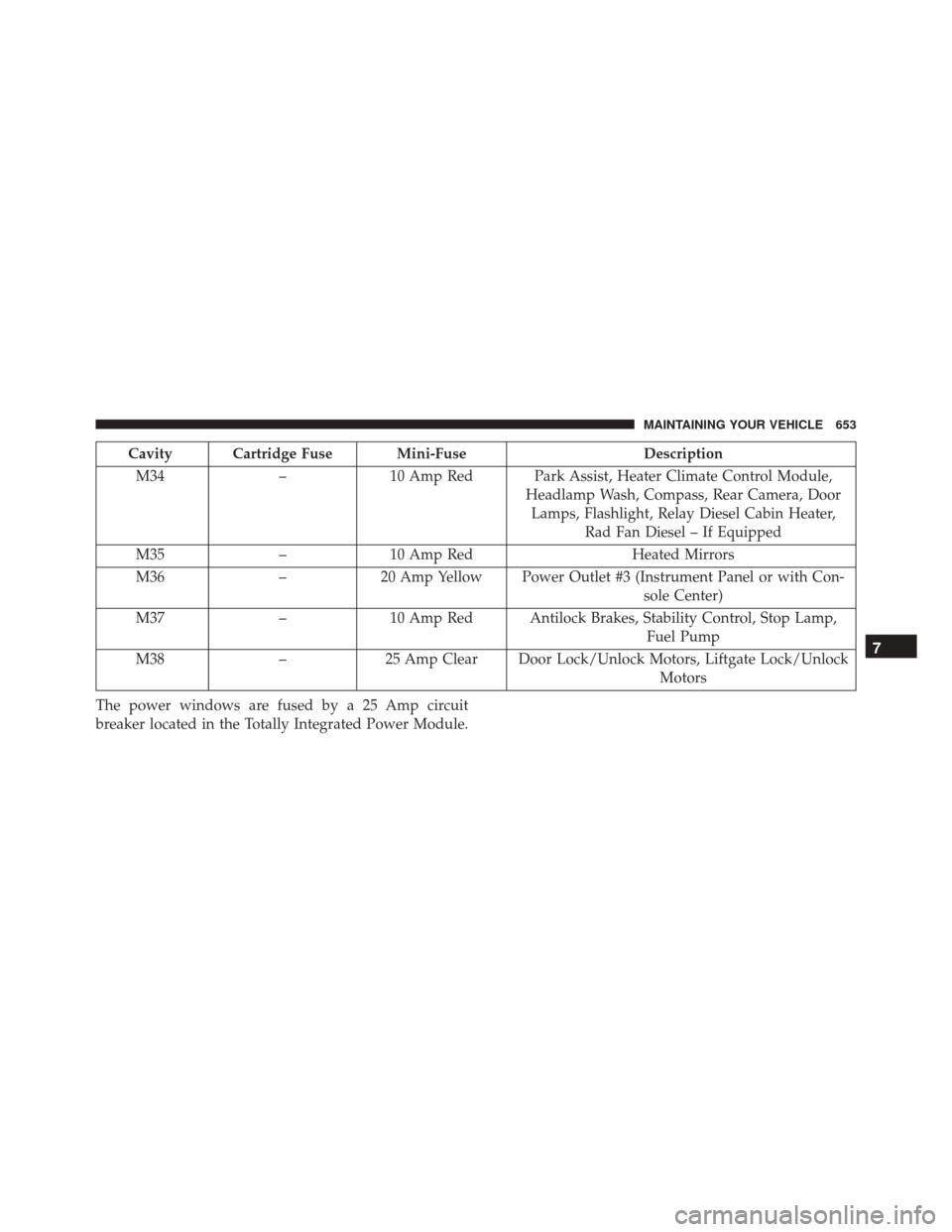
Cavity Cartridge Fuse Mini-FuseDescription
M34 –10 Amp Red Park Assist, Heater Climate Control Module,
Headlamp Wash, Compass, Rear Camera, DoorLamps, Flashlight, Relay Diesel Cabin Heater, Rad Fan Diesel – If Equipped
M35 –10 Amp Red Heated Mirrors
M36 –20 Amp Yellow Power Outlet #3 (Instrument Panel or with Con-
sole Center)
M37 –10 Amp Red Antilock Brakes, Stability Control, Stop Lamp,
Fuel Pump
M38 –25 Amp Clear Door Lock/Unlock Motors, Liftgate Lock/Unlock
Motors
The power windows are fused by a 25 Amp circuit
breaker located in the Totally Integrated Power Module.
7
MAINTAINING YOUR VEHICLE 653