hvac DODGE GRAND CARAVAN 2019 Owners Manual
[x] Cancel search | Manufacturer: DODGE, Model Year: 2019, Model line: GRAND CARAVAN, Model: DODGE GRAND CARAVAN 2019Pages: 490, PDF Size: 3.84 MB
Page 111 of 490
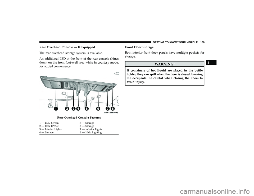
Rear Overhead Console — If Equipped
The rear overhead storage system is available.
An additional LED at the front of the rear console shines
down on the front foot-well area while in courtesy mode,
for added convenience.Front Door Storage
Both interior front door panels have multiple pockets for
storage.
WARNING!
If containers of hot liquid are placed in the bottle
holder, they can spill when the door is closed, burning
the occupants. Be careful when closing the doors to
avoid injury.
Rear Overhead Console Features
1 — LCD Screen5 — Storage
2 — Rear HVAC 6 — Storage
3 — Interior Lights 7 — Interior Lights
4 — Storage 8 — Halo Lighting
3
GETTING TO KNOW YOUR VEHICLE 109
Page 209 of 490
NOTE:
•Air bag covers may not be obvious in the interior trim,
but they will open during air bag deployment.
• After any collision, the vehicle should be taken to an
authorized dealer immediately.
Enhanced Accident Response System
In the event of an impact, if the communication network
remains intact, and the power remains intact, depending
on the nature of the event, the ORC will determine whether
to have the Enhanced Accident Response System perform
the following functions:
• Cut off fuel to the engine (If Equipped)
• Cut off battery power to the electric motor (If Equipped)
• Flash hazard lights as long as the battery has power
• Turn on the interior lights, which remain on as long as
the battery has power or for 15 minutes from the
intervention of the Enhanced Accident Response Sys-
tem.
• Unlock the power door locks. Your vehicle may also be designed to perform any of these
other functions in response to the Enhanced Accident
Response System:
•
Turn off the Fuel Filter Heater, Turn off the HVAC
Blower Motor, Close the HVAC Circulation Door
• Cut off battery power to the:
• Engine
• Electric Motor (if equipped)
• Electric power steering
• Brake booster
• Electric park brake
• Automatic transmission gear selector
• Horn
• Front wiper
• Headlamp washer pump5
SAFETY 207
Page 295 of 490
The numbers inside the TIPM cover correspond to the
following table.
CavityCartridge Fuse Mini-Fuse Description
J1 40 Amp Green –Power Folding Seat
J2 30 Amp Pink –Power Liftgate Module
J3 30 Amp Pink –Rear Door Module
J4 25 Amp Clear –Driver Door Node
J5 25 Amp Clear –Passenger Door Node
J6 40 Amp Green –Antilock Brakes Pump/Stability Control Sys-
tem
J7 30 Amp Pink –Antilock Brakes Valve/Stability Control Sys-
tem
J8 40 Amp Green –Power Memory Seat – If Equipped
J9 –– Not Used
J10 30 Amp Pink –Headlamp Wash/Manifold Tuning Valve – If
Equipped
J11 30 Amp Pink –Power Sliding Door Module/Anti–Theft
Module – If Equipped
J12 30 Amp Pink –HVAC Rear Blower, Radiator Fan Motor
J13 60 Amp Yellow –Ignition Off Draw (IOD) – Main
J14 40 Amp Green –Rear Window Defogger
7
IN CASE OF EMERGENCY 293
Page 347 of 490
CAUTION!
Do not use chemical flushes in your air conditioning
system as the chemicals can damage your air condition-
ing components. Such damage is not covered by the
New Vehicle Limited Warranty.
Refrigerant Recovery And Recycling R-134a — If
Equipped
R-134a Air Conditioning Refrigerant is a hydrofluoro-
carbon (HFC) that is an ozone-friendly substance. The
manufacturer recommends that air conditioning service be
performed by an authorized dealer or other service facili-
ties using recovery and recycling equipment.
NOTE:Use only manufacturer approved A/C system PAG
compressor oil and refrigerants.
A/C Air Filter
Refer to the “Maintenance Plan” in the “Scheduled Servic-
ing” chapter for the proper maintenance intervals.
WARNING!
Do not remove the cabin air filter while the vehicle is
running, or while the ignition is in the ACC or ON/
RUN mode. With the cabin air filter removed and the
blower operating, the blower can contact hands and
may propel dirt and debris into your eyes, resulting in
personal injury.
The A/C air filter is located in the fresh air inlet behind the
glove compartment. Perform the following procedure to
replace the filter:
1. Open the glove compartment and remove all contents.
2. Push in on the sides of the glove compartment, remove tether and lower the door.
3. Pivot the glove compartment downward.
4. Disengage the two retaining tabs that secure the filter cover to the HVAC housing, and remove the cover.
8
SERVICING AND MAINTENANCE 345