Power button DODGE HORNET 2023 Owner's Manual
[x] Cancel search | Manufacturer: DODGE, Model Year: 2023, Model line: HORNET, Model: DODGE HORNET 2023Pages: 288, PDF Size: 14.2 MB
Page 132 of 288
130MULTIMEDIA
UCONNECT SETTINGS
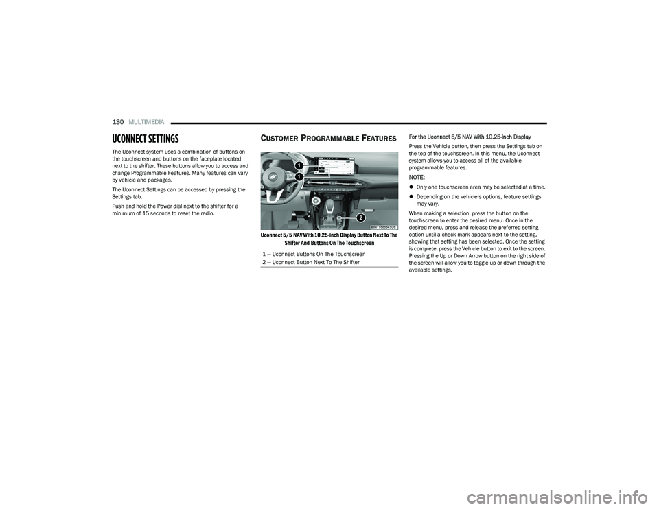
The Uconnect system uses a combination of buttons on
the touchscreen and buttons on the faceplate located
next to the shifter. These buttons allow you to access and
change Programmable Features. Many features can vary
by vehicle and packages.
The Uconnect Settings can be accessed by pressing the
Settings tab.
Push and hold the Power dial next to the shifter for a
minimum of 15 seconds to reset the radio.
CUSTOMER PROGRAMMABLE FEATURES
Uconnect 5/5 NAV With 10.25-inch Display Button Next To The
Shifter And Buttons On The Touchscreen
For the Uconnect 5/5 NAV With 10.25-inch Display
Press the Vehicle button, then press the Settings tab on
the top of the touchscreen. In this menu, the Uconnect
system allows you to access all of the available
programmable features.
NOTE:
Only one touchscreen area may be selected at a time.
Depending on the vehicle’s options, feature settings
may vary.
When making a selection, press the button on the
touchscreen to enter the desired menu. Once in the
desired menu, press and release the preferred setting
option until a check mark appears next to the setting,
showing that setting has been selected. Once the setting
is complete, press the Vehicle button to exit to the screen.
Pressing the Up or Down Arrow button on the right side of
the screen will allow you to toggle up or down through the
available settings.
1 — Uconnect Buttons On The Touchscreen
2 — Uconnect Button Next To The Shifter
23_GG_OM_EN_USC_t.book Page 130
Page 145 of 288
MULTIMEDIA143
Seats & Comfort
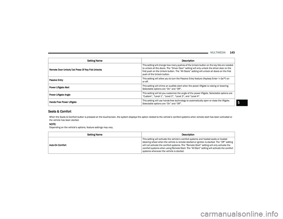
Remote Door Unlock/1st Press Of Key Fob Unlocks This setting will change how many pushes of the Unlock button on the key fob are needed
to unlock all the doors. The “Driver Door” setting will only unlock the driver door on the
first push on the Unlock button. The “All Doors” setting will unlock all doors on the first
push of the Unlock button.
Passive Entry This setting will allow you to turn the Passive Entry feature (Keyless Enter ‘n Go™) on
or off.
Power Liftgate Alert This setting will chime an audible alert when the power liftgate is raising or lowering.
Selectable options are “On” and “Off”.
Power Liftgate Angle This setting will let you customize the angle of the power liftgate. Selectable options are
“Custom”, “Level 1”, “Level 2”, “Level 3”, and “Level 4”.
Hands Free Power Liftgate This setting will use hands-free technology to automatically open or close the liftgate.
Selectable options are “On” and “Off”.
Setting Name
Description
When the Seats & Comfort button is pressed on the touchscreen, the system displays the option related to the vehicle’s comfort systems when remote start has been activated or
the vehicle has been started.
NOTE:Depending on the vehicle’s options, feature settings may vary.
Setting NameDescription
Auto-On Comfort This setting will activate the vehicle’s comfort systems and heated seats or heated
steering wheel when the vehicle is remote started or ignition is started. The “Off” setting
will not activate the comfort systems. The “Remote Start” setting will only activate the
comfort systems when using Remote Start. The “All Start” setting will activate the comfort
systems whenever the vehicle is started.
5
23_GG_OM_EN_USC_t.book Page 143
Page 206 of 288
204IN CASE OF EMERGENCY
SOS Call
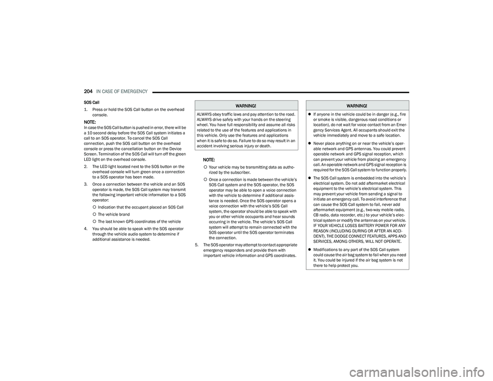
1. Press or hold the SOS Call button on the overhead
console.
NOTE:In case the SOS Call button is pushed in error, there will be
a 10 second delay before the SOS Call system initiates a
call to an SOS operator. To cancel the SOS Call
connection, push the SOS call button on the overhead
console or press the cancellation button on the Device
Screen. Termination of the SOS Call will turn off the green
LED light on the overhead console.
2. The LED light located next to the SOS button on the overhead console will turn green once a connection
to a SOS operator has been made.
3. Once a connection between the vehicle and an SOS operator is made, the SOS Call system may transmit
the following important vehicle information to a SOS
operator:
Indication that the occupant placed an SOS Call
The vehicle brand
The last known GPS coordinates of the vehicle
4. You should be able to speak with the SOS operator through the vehicle audio system to determine if
additional assistance is needed.
NOTE:
Your vehicle may be transmitting data as autho -
rized by the subscriber.
Once a connection is made between the vehicle’s
SOS Call system and the SOS operator, the SOS
operator may be able to open a voice connection
with the vehicle to determine if additional assis -
tance is needed. Once the SOS operator opens a
voice connection with the vehicle’s SOS Call
system, the operator should be able to speak with
you or other vehicle occupants and hear sounds
occurring in the vehicle. The vehicle’s SOS Call
system will attempt to remain connected with the
SOS operator until the SOS operator terminates
the connection.
5. The SOS operator may attempt to contact appropriate emergency responders and provide them with
important vehicle information and GPS coordinates.
WARNING!
ALWAYS obey traffic laws and pay attention to the road.
ALWAYS drive safely with your hands on the steering
wheel. You have full responsibility and assume all risks
related to the use of the features and applications in
this vehicle. Only use the features and applications
when it is safe to do so. Failure to do so may result in an
accident involving serious injury or death.
WARNING!
If anyone in the vehicle could be in danger (e.g., fire
or smoke is visible, dangerous road conditions or
location), do not wait for voice contact from an Emer -
gency Services Agent. All occupants should exit the
vehicle immediately and move to a safe location.
Never place anything on or near the vehicle’s oper -
able network and GPS antennas. You could prevent
operable network and GPS signal reception, which
can prevent your vehicle from placing an emergency
call. An operable network and GPS signal reception is
required for the SOS Call system to function properly.
The SOS Call system is embedded into the vehicle’s
electrical system. Do not add aftermarket electrical
equipment to the vehicle’s electrical system. This
may prevent your vehicle from sending a signal to
initiate an emergency call. To avoid interference that
can cause the SOS Call system to fail, never add
aftermarket equipment (e.g., two-way mobile radio,
CB radio, data recorder, etc.) to your vehicle’s elec -
trical system or modify the antennas on your vehicle.
IF YOUR VEHICLE LOSES BATTERY POWER FOR ANY
REASON (INCLUDING DURING OR AFTER AN ACCI -
DENT), THE DODGE CONNECT FEATURES, APPS AND
SERVICES, AMONG OTHERS, WILL NOT OPERATE.
Modifications to any part of the SOS Call system
could cause the air bag system to fail when you need
it. You could be injured if the air bag system is not
there to help protect you.
23_GG_OM_EN_USC_t.book Page 204
Page 207 of 288
IN CASE OF EMERGENCY205
SOS Call System Limitations
Vehicles sold in Mexico DO NOT have SOS Call system
capabilities.
SOS or other emergency line operators in Mexico may not
answer or respond to SOS system calls.
If the SOS Call system detects a malfunction, any of the
following may occur at the time the malfunction is
detected, and at the beginning of each ignition cycle:
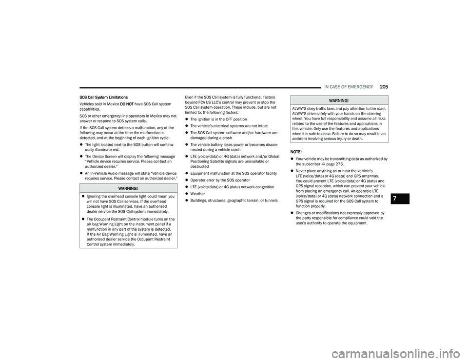
The light located next to the SOS button will continu -
ously illuminate red.
The Device Screen will display the following message
“Vehicle device requires service. Please contact an
authorized dealer.”
An In-Vehicle Audio message will state “Vehicle device
requires service. Please contact an authorized dealer.” Even if the SOS Call system is fully functional, factors
beyond FCA US LLC’s control may prevent or stop the
SOS Call system operation. These include, but are not
limited to, the following factors:
The ignition is in the OFF position
The vehicle’s electrical systems are not intact
The SOS Call system software and/or hardware are
damaged during a crash
The vehicle battery loses power or becomes discon -
nected during a vehicle crash
LTE (voice/data) or 4G (data) network and/or Global
Positioning Satellite signals are unavailable or
obstructed
Equipment malfunction at the SOS operator facility
Operator error by the SOS operator
LTE (voice/data) or 4G (data) network congestion
Weather
Buildings, structures, geographic terrain, or tunnels
NOTE:
Your vehicle may be transmitting data as authorized by
the subscriber Úpage 275.
Never place anything on or near the vehicle’s
LTE (voice/data) or 4G (data) and GPS antennas.
You could prevent LTE (voice/data) or 4G (data) and
GPS signal reception, which can prevent your vehicle
from placing an emergency call. An operable LTE
(voice/data) or 4G (data) network connection and a
GPS signal is required for the SOS Call system to
function properly.
Changes or modifications not expressly approved by
the party responsible for compliance could void the
user's authority to operate the equipment.
WARNING!
Ignoring the overhead console light could mean you
will not have SOS Call services. If the overhead
console light is illuminated, have an authorized
dealer service the SOS Call system immediately.
The Occupant Restraint Control module turns on the
air bag Warning Light on the instrument panel if a
malfunction in any part of the system is detected.
If the Air Bag Warning Light is illuminated, have an
authorized dealer service the Occupant Restraint
Control system immediately.
WARNING!
ALWAYS obey traffic laws and pay attention to the road.
ALWAYS drive safely with your hands on the steering
wheel. You have full responsibility and assume all risks
related to the use of the features and applications in
this vehicle. Only use the features and applications
when it is safe to do so. Failure to do so may result in an
accident involving serious injury or death.
7
23_GG_OM_EN_USC_t.book Page 205
Page 216 of 288
214IN CASE OF EMERGENCY
16. Apply the adhesive label from the sealant bottle
where it can be easily seen by the driver as a
reminder that the tire has been treated with a Tire
Inflator Kit, as well as not to exceed the speed
restriction for the treated tire.
CHECKING AND RESTORING TIRE
P
RESSURE
The compressor can also be used to check and, if
necessary, restore the tire pressure.
Proceed as follows:
1. Plug the power cord in the vehicle’s power outlet.
2. Release the quick connector and connect it directly to
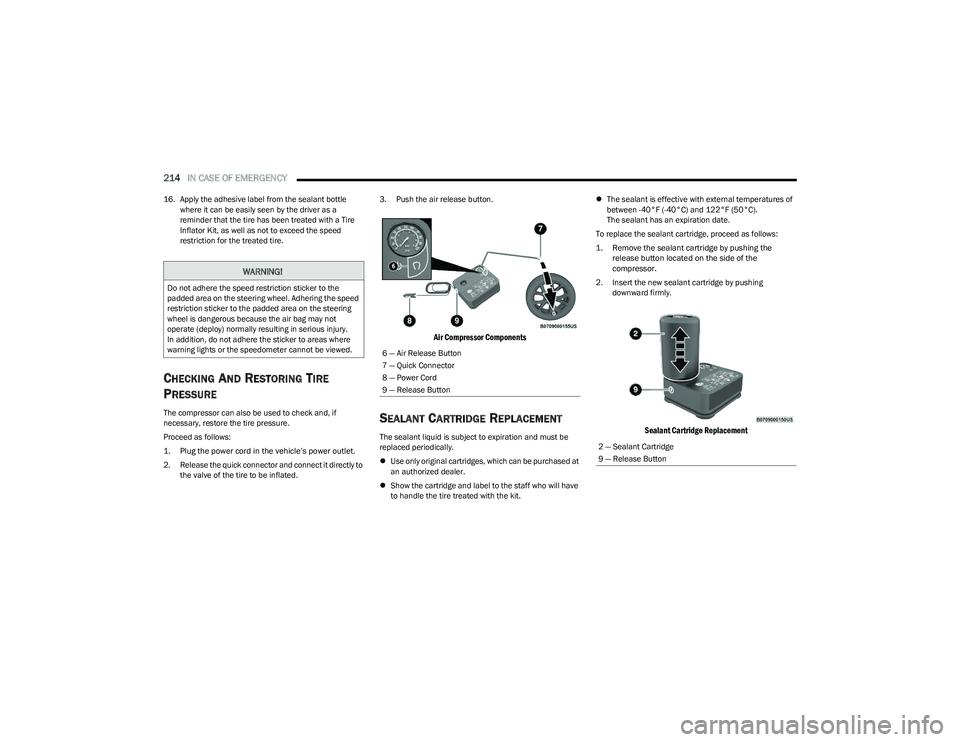
the valve of the tire to be inflated. 3. Push the air release button.
Air Compressor Components
SEALANT CARTRIDGE REPLACEMENT
The sealant liquid is subject to expiration and must be
replaced periodically.
Use only original cartridges, which can be purchased at
an authorized dealer.
Show the cartridge and label to the staff who will have
to handle the tire treated with the kit.
The sealant is effective with external temperatures of
between -40°F (-40°C) and 122°F (50°C).
The sealant has an expiration date.
To replace the sealant cartridge, proceed as follows:
1. Remove the sealant cartridge by pushing the release button located on the side of the
compressor.
2. Insert the new sealant cartridge by pushing downward firmly.
Sealant Cartridge Replacement
WARNING!
Do not adhere the speed restriction sticker to the
padded area on the steering wheel. Adhering the speed
restriction sticker to the padded area on the steering
wheel is dangerous because the air bag may not
operate (deploy) normally resulting in serious injury.
In addition, do not adhere the sticker to areas where
warning lights or the speedometer cannot be viewed.
6 — Air Release Button
7 — Quick Connector
8 — Power Cord
9 — Release Button
2 — Sealant Cartridge
9 — Release Button
23_GG_OM_EN_USC_t.book Page 214