change wheel DODGE HORNET 2023 Owners Manual
[x] Cancel search | Manufacturer: DODGE, Model Year: 2023, Model line: HORNET, Model: DODGE HORNET 2023Pages: 288, PDF Size: 14.2 MB
Page 8 of 288
6
SERVICING AND MAINTENANCE
SCHEDULED SERVICING ................................................ 223
Maintenance Plan ..................................................... 224
ENGINE COMPARTMENT................................................. 226 2.0L Engine .............................................................. 226Checking Oil Level ..................................................... 227
Adding Washer Fluid ................................................ 227Maintenance-Free Battery........................................ 227Pressure Washing ..................................................... 228
VEHICLE MAINTENANCE ................................................. 228 Engine Oil................................................................... 228
Engine Oil Filter ......................................................... 228
Engine Air Cleaner Filter ........................................... 229
Air Conditioner Maintenance ................................... 229
Body Lubrication ....................................................... 230Wiper Blades ............................................................ 230
Exhaust System ........................................................ 232
Cooling System.......................................................... 233
Brake System ........................................................... 236
Automatic Transmission —
If Equipped ................................................................ 236
Fuses ......................................................................... 237
Bulb Replacement ................................................... 246
TIRES ................................................................................ 246 Tire Safety Information ............................................ 246
Tires — General Information .................................... 254
Tire Types................................................................... 257
Spare Tires — If Equipped ........................................ 258Snow Traction Devices ............................................ 259
Tire Rotation Recommendations ............................ 260 DEPARTMENT OF TRANSPORTATION UNIFORM
TIRE QUALITY GRADES .................................................. 260
Treadwear ................................................................. 260Traction Grades ........................................................ 261Temperature Grades ................................................ 261
STORING THE VEHICLE ................................................... 261
BODYWORK ...................................................................... 262 Protection From Atmospheric Agents ...................... 262Body And Underbody Maintenance ......................... 262
Preserving The Bodywork ......................................... 263
INTERIORS ....................................................................... 263 Seats And Fabric Parts ............................................. 263
Plastic And Coated Parts .......................................... 264Leather Surfaces ...................................................... 264
Glass Surfaces ......................................................... 264
TECHNICAL SPECIFICATIONS
VEHICLE IDENTIFICATION NUMBER (VIN)..................... 265
BRAKE SYSTEM .............................................................. 265
WHEEL AND TIRE TORQUE SPECIFICATIONS .............. 265 Torque Specifications ............................................... 265
FUEL REQUIREMENTS ..................................................... 266 2.0L Engine ............................................................... 266Reformulated Gasoline ........................................... 266Gasoline/Oxygenate Blends ................................... 266E-85 Usage In Non-Flex Fuel Vehicles ..................... 267CNG And LP Fuel System Modifications.................. 267
Methylcyclopentadienyl Manganese
Tricarbonyl (MMT) In Gasoline ................................. 267
Materials Added To Fuel .......................................... 267Fuel System Cautions ............................................... 267 FLUID CAPACITIES ...........................................................268
ENGINE FLUIDS AND LUBRICANTS ................................269
CHASSIS FLUIDS AND LUBRICANTS ..............................269
CUSTOMER ASSISTANCE
SUGGESTIONS FOR OBTAINING SERVICE FOR
YOUR VEHICLE ................................................................. 270 Prepare For The Appointment .................................. 270
Prepare A List ............................................................ 270Be Reasonable With Requests ................................. 270
IF YOU NEED ASSISTANCE .............................................270 Roadside Assistance ................................................. 271
FCA US LLC Customer Center ................................... 272
FCA Canada Inc. Customer Care .............................. 272
Mexico ........................................................................ 272
Puerto Rico And US Virgin Islands............................ 272
Customer Assistance For The Hearing Or
Speech Impaired (TDD/TTY) ..................................... 272
Service Contract ....................................................... 272
WARRANTY INFORMATION.............................................273
MOPAR® PARTS ..............................................................273
REPORTING SAFETY DEFECTS ......................................273 In The 50 United States And Washington, D.C........ 273
In Canada................................................................... 273
PUBLICATION ORDER FORMS .......................................274
CHANGE OF OWNERSHIP OR ADDRESS.......................274
GENERAL INFORMATION................................................. 275
23_GG_OM_EN_USC_t.book Page 6
Page 21 of 288
GETTING TO KNOW YOUR VEHICLE19
TO EXIT REMOTE START MODE
To drive the vehicle after starting the Remote Start
system, push and release the START/STOP ignition button
prior to the end of the 15 minute cycle.
The Remote Start system will turn the engine off if the
Remote Start button on the key fob is pushed again, or if
the engine is allowed to run for the entire 15 minute cycle.
Once the ignition is placed in the ON/RUN position, the
climate controls will resume previously set operations
(temperature, blower control, etc.).
NOTE:
For vehicles not equipped with the Keyless
Enter ‘n Go™ — Passive Entry feature, the ignition
switch must be in the ON/RUN position in order to drive
the vehicle.
For vehicles equipped with the Keyless Enter ‘n Go™ —
Passive Entry feature, the message “Remote Start
Active — Push Start Button” will show in the instrument
cluster display until you push the START/STOP ignition
button.
To avoid unintentional shutdowns, the system will
disable for two seconds after receiving a valid
Remote Start request.
REMOTE START FRONT DEFROST
A
CTIVATION — IF EQUIPPED
When Remote Start is active, and the outside ambient
temperature is 40°F (4.5°C) or below, the system will
automatically activate front defrost for 15 minutes or less.
The timing is dependent on the ambient temperature.
Once the timer expires, the system will automatically
adjust the settings depending on ambient conditions. See
“Remote Start Comfort Systems — If Equipped” in the next
section for detailed operation.
REMOTE START COMFORT SYSTEMS —
I
F EQUIPPED
When Remote Start is activated, the front and rear defrost
will automatically turn on in cold weather. The heated
steering wheel and driver heated seat feature will turn on
if programmed in the Comfort menu screen within
Uconnect Settings
Úpage 130. In warm weather, the
driver vented seat feature will automatically turn on when
Remote Start is activated, if programmed in the Comfort
menu screen. The vehicle will adjust the climate control
settings depending on the outside ambient temperature.
Automatic Temperature Control (ATC) — If Equipped
The climate controls will automatically adjust to the
optimal temperature and mode settings depending on the
outside ambient temperature. This will occur until the
ignition is placed in the ON/RUN position where the
climate controls will resume their previous settings. Manual Temperature Control (MTC) — If Equipped
In ambient temperatures of 40°F (4.5°C) or below, the
climate settings will default to maximum heat, with
fresh air entering the cabin. If the front defrost timer
expires, the vehicle will enter Mix mode.
In ambient temperatures from 40°F (4.5°C) to 78°F
(26°C), the climate settings will be based on the last
settings selected by the driver.
In ambient temperatures of 78°F (26°C) or above, the
climate settings will default to MAX A/C, Bi-Level mode,
with Recirculation on.
For more information on ATC, MTC, and climate control
settings, see
Úpage 46.
NOTE:These features will stay on through the duration of Remote
Start, or until the ignition is placed in the ON/RUN
position. The climate control settings will change, and exit
the automatic defaults, if manually adjusted by the driver
while the vehicle is in Remote Start mode. This includes
turning the climate controls off using the OFF button.
REMOTE START WINDSHIELD WIPER
D
E-ICER ACTIVATION — IF EQUIPPED
When Remote Start is active and the outside ambient
temperature is less than 33°F (0.6°C), the Windshield
Wiper De-Icer will activate. Exiting Remote Start will
resume its previous operation. If the Windshield Wiper
De-Icer was active, the timer and operation will continue.
2
23_GG_OM_EN_USC_t.book Page 19
Page 50 of 288
48GETTING TO KNOW YOUR VEHICLE
Driver And Passenger Temperature
Control Buttons
These buttons provide the driver and passenger with
independent temperature control.
SYNC Button
Press the SYNC button on the touchscreen to
toggle the Sync feature on/off. The SYNC
indicator is illuminated when SYNC is on. SYNC
is used to synchronize the passenger
temperature setting with the driver temperature setting.
Changing the passenger temperature setting while in
SYNC will automatically exit this feature.
NOTE:The SYNC button is only available on the touchscreen.
Blower Control
Blower Control is used to regulate the amount of
air forced through the Climate Control system.
There are seven blower speeds available.
Adjusting the blower will cause automatic mode
to switch to manual operation. The speeds can be selected
using either the blower control buttons on the faceplate or
the buttons on the touchscreen.
Faceplate
Press the small blower icon button to decrease the blower
speed, or press the large blower icon button to increase
the blower speed.
Touchscreen
Blower speed can also be selected by pressing a number
on the blower bar area.
Mode Control
Select Mode by pressing one of the Mode
buttons on the touchscreen, or the faceplate,
to change the airflow distribution mode. The
airflow distribution mode can be adjusted so air
comes from the instrument panel outlets, floor outlets,
defrost outlets and demist outlets.
Panel Mode
Air comes from the outlets in the instrument
panel. Each of these outlets can be individually
adjusted to direct the flow of air. The air vanes
of the center outlets and outboard outlets can
be moved up and down or side to side to regulate airflow
direction. There is a shut-off wheel located below the air
vanes to shut off or adjust the amount of airflow from
these outlets.
Bi-Level Mode
Air comes from the instrument panel outlets
and floor outlets. A slight amount of air is
directed through the defrost and side window
demister outlets.
NOTE:Bi-Level mode is designed under comfort conditions to
provide cooler air out of the panel outlets and warmer air
from the floor outlets.
Floor Mode
Air comes from the floor outlets. A slight
amount of air is directed through the defrost,
side window demister outlets, and panel
outboard outlets.
Defrost Mode
Air comes from the windshield and side
window demist outlets. When the defrost
button is selected, the blower level may
increase. Use Defrost mode with maximum
temperature settings for best windshield and side window
defrosting and defogging. When toggling the front defrost
mode button, the Climate Control system will return to the
previous setting.
Mix Mode
Air is directed through the floor, defrost, and
side window demister outlets. This setting
works best in cold or snowy conditions that
require extra heat to the windshield. This
setting is good for maintaining comfort while reducing
moisture on the windshield. A slight amount of air is also
directed through the panel outboard outlets.
Push upward on the driver’s or
passenger’s side toggle switch on the
faceplate, or press and slide the
temperature bar towards the red arrow
button on the touchscreen for warmer
temperature settings.
Push downward the driver’s or
passenger’s side toggle switch on the
faceplate, or press and slide the
temperature bar towards the blue arrow
button on the touchscreen for cooler
temperature settings.
23_GG_OM_EN_USC_t.book Page 48
Page 51 of 288
GETTING TO KNOW YOUR VEHICLE49
Combine Modes
Dual Level Combination
Front Defrost and Panel Mode
Tri-Level Combination
Front Defrost, Panel Mode, and Floor Mode
Climate Control OFF Button
Press and release this button on the
touchscreen, or push and release the
button on the faceplate to turn the
Climate Control ON/OFF.
AUTOMATIC TEMPERATURE
CONTROL (ATC)
Automatic Operation
1. Push the AUTO button on the faceplate, or the
AUTO button on the touchscreen (if equipped) on the
Automatic Temperature Control (ATC) Panel.
2. Next, adjust the temperature you would like the system to maintain by adjusting the temperature
control buttons. Once the desired temperature is
displayed, the system achieves and automatically
maintains that comfort level.
3. When the system is set up for your comfort level, it is not necessary to change the settings. You experience
the greatest efficiency by simply allowing the system
to function automatically.
NOTE:
It is not necessary to move the temperature settings for
cold or hot vehicles. The system automatically adjusts
the temperature, mode, and blower speed to provide
comfort as quickly as possible.
The temperature can be displayed in US or Metric units
by selecting the US/Metric customer-programmable
feature.
To provide you with maximum comfort in the Automatic
mode during cold start-ups, the blower fan remains on low
until the engine warms up. The blower increases in speed
and transition into Auto mode.
Manual Operation Override
This system offers a full complement of manual override
features. The AUTO symbol in the front ATC display will be
turned off when the system is being used in the manual
mode.
CLIMATE VOICE COMMANDS
Adjust vehicle temperatures hands-free and keep
everyone comfortable while you keep moving ahead.
Push the VR button on the steering wheel. After the beep,
say one of the following commands:
“Set the driver temperature to 70 degrees ”
“Set the passenger temperature to 70 degrees ”
Did You Know: Voice Command for Climate may only be
used to adjust the interior temperature of your vehicle.
Voice Command will not work to adjust the heated seats
or steering wheel if equipped.
OPERATING TIPS
Refer to the chart at the end of this section for suggested
control settings for various weather conditions.
Summer Operation
The engine cooling system must be protected with a
high-quality antifreeze coolant to provide proper corrosion
protection and to protect against engine overheating.
OAT coolant (conforming to MS.90032) is recommended.
The driver or front passenger can combine
two or three of the modes described by
selecting them individually on the climate
control screen. Combine modes by
pressing each icon on the touchscreen.
2
23_GG_OM_EN_USC_t.book Page 49
Page 70 of 288
68GETTING TO KNOW YOUR INSTRUMENT PANEL
Unstored Messages
This message type is displayed indefinitely or until the
condition that activated the message is cleared. Exam -
ples of this message type are “Turn Signal On” (if a turn
signal is left on) and “Lights On” (if driver leaves the
vehicle with the lights on).
Unstored Messages Until RUN
These messages deal primarily with the Remote Start
feature. This message type is displayed until the igni -
tion is in the RUN state. Examples of this message type
are “Remote Start Canceled - Door Ajar” and
“Press Brake Pedal and Push Button to Start.”
Five Second Unstored Messages
When the appropriate conditions occur, this type of
message takes control of the main display area for
five seconds and then returns to the previous screen.
An example of this message type is “Automatic High
Beams On.”
OIL CHANGE RESET
Use this QR code to access your digital
experience.
Your vehicle is equipped with an
engine oil change indicator system.
A message will display in the instru -
ment cluster display for five
seconds to indicate the next sched -
uled oil change interval is due. The
engine oil change indicator system is duty cycle based,
which means the engine oil change interval may fluc -
tuate, dependent upon your personal driving style.
Unless reset, this message will continue to display
each time the ignition is cycled to the ON/RUN position.
To reset the oil change indicator after performing the
scheduled maintenance, refer to the following procedure:
1. Without pressing the brake pedal, push the ENGINE START/STOP button and cycle the ignition to the
ON/RUN position (do not start the engine).
2. Fully press the accelerator pedal, slowly, three times within ten seconds.
3. Cycle the ignition to the OFF position.
NOTE:If the indicator message illuminates when you start the
vehicle, the oil change indicator system did not reset. If
necessary, repeat this procedure.
OIL CHANGE INDICATOR SYSTEM
Your vehicle is equipped with an engine oil change
indicator system. The “Oil Change Due” message will
display in the instrument cluster display for five seconds
after a single chime has sounded, to indicate the next
scheduled oil change interval. The engine oil change
indicator system is duty cycle based, which means the
engine oil change interval may fluctuate, dependent upon
your personal driving style.
GEAR SHIFT INDICATOR (GSI) —
I
F EQUIPPED
The GSI system is enabled on vehicles with a manual
transmission, or when a vehicle with an automatic
transmission is in manual shift mode. The GSI provides
the driver with a visual indication when the recommended gear shift point has been reached. This indication notifies
the driver that changing gear will allow a reduction in fuel
consumption. When the up shift indicator is shown on the
instrument cluster display, the GSI is advising the driver to
engage a higher gear. When the down shift indicator is
shown on the display, the GSI is advising the driver to
engage a lower gear.
The GSI remains illuminated until the driver changes
gears, or the driving conditions return to a situation where
changing gear is not required to improve fuel
consumption.
INSTRUMENT CLUSTER DISPLAY MENU
I
TEMS
The instrument cluster display can be used to view the
main menu items for several features. Use the up and
down arrow buttons to scroll through the driver
interactive display menu options until the desired menu is
reached.
NOTE:The instrument cluster display menu items display in the
center of the instrument cluster. Menu items may vary
depending on your vehicle features.
Main Menu
Use the Thumbwheel to scroll Up and Down through the
Menu options. Press the Thumbwheel to enter and exit the
highlighted menu option.
NOTE:These Menu options may vary based on your vehicles trim
level.
23_GG_OM_EN_USC_t.book Page 68
Page 71 of 288
GETTING TO KNOW YOUR INSTRUMENT PANEL69
SPEEDOMETER
The Speedometer menu options may consist of the
following:
Digital speed and speed unit (MPH or km/h)
Gear Shift Indicator (GSI)
Gear
Drive mode name
The speed units can be changed from MPH to km/h by
pressing the Thumbwheel.
NAVIGATION — IF EQUIPPED
Turn the Thumbwheel up or down to increase or decrease
the zoom on this screen. Press the Thumbwheel to go
back to the initial frame. The zoom level is automatically
reset to the factory settings whenever the engine is
restarted.
The following information is shown:
Direction Indicators
Distance to next change of direction (in miles or kilome -
ters, depending on instrument panel settings)
Suggested lanes
Address of the road to be followed after the change of
direction Press and hold the Thumbwheel to disable the indications
in the right-hand ring for the current navigation. If a
predicted route is selected, the route shall start without
further confirmation.
NOTE:During projection modes (Apple CarPlay® or
Android Auto™) the native map is not available.
PHONE
This menu displays the current status of a phone
connected to the vehicle via Bluetooth®. The System
supports up to two phones connected at the same time.
Information available in cluster depends on which phone
is dynamically selected by the user in each moment (i.e.
the phone in focus), to enter and select one of the phone
connected user should press Thumbwheel
If no phone is connected, the menu will not function when
the
OK button is pushed. Otherwise, if a phone is
connected, push the OK button to enter the menu.
The following items will display:
Recent calls: displays a list of the last 10 calls.
SMS reader: displays the last 10 text messages and if
they are read or unread.
Favorite numbers: displays a maximum of 10 favorite
numbers.
PERFORMANCE
Performance page content automatically changes
according to the selected drive mode.
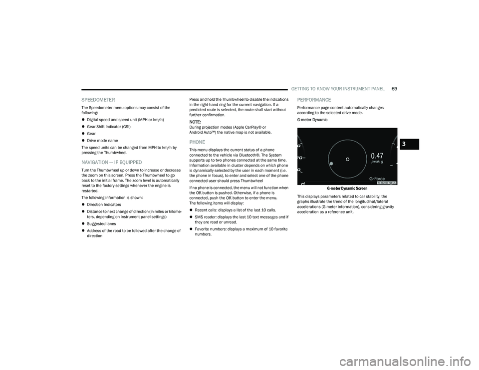
G-meter Dynamic
G-meter Dynamic Screen
This displays parameters related to car stability, the
graphs illustrate the trend of the longitudinal/lateral
accelerations (G-meter information), considering gravity
acceleration as a reference unit.
3
23_GG_OM_EN_USC_t.book Page 69
Page 93 of 288
STARTING AND OPERATING91
NOTE:
The Mode button also activates the Adaptive Cruise
Control (ACC) system. Pushing the Mode button will
switch between activating the Active Speed Limiter or
the Adaptive Cruise Control systems. They cannot be
active at the same time.
The Active Speed Limiter can be set while the vehicle is
in motion, or with the gear selector in the PARK posi -
tion.
ACTIVATION
To activate the feature, push the Mode button located on
the left side of the steering wheel. A white indicator light in
the instrument cluster display to signal that Active Speed
Limiter has been enabled.
After the Active Speed Limiter system is enabled, activate
the system by setting the speed limit of the vehicle by
pushing the SET switch upward or downward.
Pushing the SET switch upward or downward to the first
detent, and releasing, will result in a 1 mph (1 km/h)
speed adjustment. Each subsequent movement of the
switch to the first detent will result in an adjustment of
1 mph (1 km/h).
If the switch is pushed upward or downward briefly to
the second detent, the set speed will adjust in 5 mph
(10 km/h) increments. The new set speed is reflected in
the instrument cluster display. If the switch is held upward or downward, the set speed
will continue to adjust until the switch is released.
NOTE:
Once the speed as been set, the indicator light in the
instrument cluster display will change to green.
If Adaptive Cruise Control (ACC) or the Active Speed
Limiter is active when the ignition is placed in the
OFF position, it will remain activated when the vehicle
is started again.
ACC will be unavailable while the Active Speed Limiter
is in use.
EXCEEDING THE SET SPEED
By fully pressing the accelerator pedal, the programmed
maximum speed can be exceeded while the device is
active.
In the event that the Active Speed Limiter set value is
exceeded manually with a driver acceleration, an audible
chime will sound. The indicator light will flash rapidly, and
a message will appear in the instrument cluster display.
The feature will remain disabled until the vehicle speed
drops below the set Active Speed Limiter value, where it
will reactivate automatically.
NOTE:While driving at a higher speed than previously set, the set
limit can be updated by pushing the SET switch upward or
downward to the new desired speed.
DEACTIVATION
To turn off Active Speed Limiter, push the Mode button
again. The indicator light in the instrument cluster display
will no longer be illuminated to confirm that the feature
has been turned off, and Adaptive Cruise Control will be
active.
The Active Speed Limiter can be deactivated by pressing
the CANC button. In this case, the system is not completely
turned off, and the driver can reactivate the Active Speed
Limiter by pressing the RES button to the previously set
speed.
INTELLIGENT SPEED ASSIST (ISA) —
IF EQUIPPED
The Intelligent Speed Assist (ISA) system
combines the Active Speed Limiter and
Traffic Sign Recognition (TSR) systems to
automatically adjust the maximum speed of
the vehicle based on detected speed limit signs.
When the ISA system is activated, the maximum speed of
the vehicle will be adjusted according to the detected
traffic signs depending on the Sign Capture Mode selected
within Uconnect Settings
Úpage 130.
4
23_GG_OM_EN_USC_t.book Page 91
Page 94 of 288
92STARTING AND OPERATING
ACTIVATION
To activate the feature, make sure the Traffic Sign
Recognition (TSR), and Intelligent Speed Assist (ISA) systems
are both enabled within Uconnect Settings
Ú
page 130, then
activate the Active Speed Limiter system by pushing the Mode
button located on the left of the steering wheel.
The white ISA indicator light in the instrument cluster
display will illuminate to signal that the system has been
enabled, but not yet detected a speed limit sign.
NOTE:Adaptive Cruise Control will be unavailable while the
ISA system is in use.
SIGN CAPTURE MODES
The way in which the ISA system sets a new maximum
vehicle speed depends on the Sign Capture Mode set
within the Uconnect system. When a new maximum speed
limit is set, the ISA indicator light in the instrument cluster
display will change from white to green.
Confirmation Mode
When Confirmation Mode is selected, and the Traffic Sign
Recognition (TSR) system detects a new speed limit sign,
the driver will confirm this new speed by pushing the
SET switch upward briefly, then releasing. This
confirmation of the new speed must be done within
five seconds of a newly detect speed limit sign being
shown in the instrument cluster display. Automatic Mode
When Automatic Mode is selected, the ISA system will
automatically adjust the maximum vehicle speed when
the TSR system detects a new speed limit sign. The new
speed is shown in the instrument cluster display.
The driver can reject this new speed by pushing the SET
switch upward briefly, then releasing within five seconds
of the new speed limit sign being detected and the speed
being adjusted.
NOTE:If a newly detected speed limit sign indicates a speed
higher or lower than the current maximum speed limit of
the Active Speed Limiter system, a message along with an
up arrow or a down arrow will appear in the instrument
cluster display to alert the driver.
EXCEEDING THE SET SPEED
By fully pressing the accelerator pedal, the maximum set
speed of the vehicle can be exceeded while the system is
active.
When the maximum set speed is exceeded, the green
indicator light on the instrument cluster display will blink
until the accelerator pedal is released and the vehicle
speed drops below the previously set maximum vehicle
speed. The ISA system will then resume normal operation.
DEACTIVATION
The ISA system will deactivate in the following situations:
When the Mode button is pushed again
When the TSR system is deactivated
When the TSR system cannot detect/display any speed
limit
When the TSR system detects the end of the speed
limit zone
CRUISE CONTROL SYSTEMS
Your vehicle is equipped with the Adaptive Cruise Control
(ACC) system. ACC will adjust the vehicle speed up to the
preset speed to maintain a distance with the vehicle
ahead.
NOTE:If Active Speed Limiter is enabled, Adaptive Cruise Control
will be unavailable, and vice versa.
ADAPTIVE CRUISE CONTROL (ACC)
Adaptive Cruise Control (ACC) increases the driving
convenience provided by Cruise Control while traveling on
highways and major roadways. However, it is not a safety
system and not designed to prevent collisions.
23_GG_OM_EN_USC_t.book Page 92
Page 96 of 288
94STARTING AND OPERATING
Adaptive Cruise Control Off
When ACC is deactivated, all ACC visualizations will not be
shown in the instrument cluster display.
Adaptive Cruise Control Ready
When ACC is activated, but the vehicle speed setting has
not been selected, the white ACC icon will illuminate above
dashes in place of a speed in the instrument cluster
display.
Adaptive Cruise Control Set
When the vehicle has reached the desired speed, push
the SET switch up or down briefly, then release. When the
ACC speed is set, the green ACC icon over the set speed
will illuminate in the instrument cluster display.
When the ACC menu screen is not being viewed in the
instrument cluster display, a green triangle will illuminate
on the speedometer at the location of the set speed.
NOTE:If the ACC system is canceled or paused, the triangle on
the speedometer will change to white, indicating the
saved set speed for when the RES button pushed.
Activating Adaptive Cruise Control (ACC)
The minimum set speed for the ACC system is 19 mph
(30 km/h).
NOTE:You cannot engage ACC under the following conditions:
When the brakes are applied
When the parking brake is applied
When the gear selector is in PARK, REVERSE or
NEUTRAL
When the vehicle speed is below the minimum speed
range
When the brakes are overheated
When the driver’s door is open at low speeds
When the driver’s seat belt is unbuckled at low speeds
When there is a stationary vehicle in front of your
vehicle in close proximity
To Activate/Deactivate
Push and release the Mode button located on the left side
of the steering wheel to activate ACC. Then proceed to
setting the desired speed as described in the next section.
NOTE:Active Speed Limiter will be unavailable while ACC is in
use.
To turn the system off, push and release the Mode button
again. At this time, the system will turn off and Active
Speed Limiter will be active.
The system will also turn off during any of the conditions
listed in “To Turn Off”
Úpage 95.
To Set A Desired Speed
When the vehicle has reached the desired speed, push
the SET switch up or down briefly, then release. The
instrument cluster display will show the set speed.
If ACC is set when the vehicle speed is
below
19 mph
(30 km/h), the set speed will default to 19 mph (30 km/h).
If either system is set when the vehicle speed is above
19 mph (30 km/h), the set speed shall be the current speed of the vehicle.
NOTE:
Keeping your foot on the accelerator pedal can cause
the vehicle to continue to accelerate beyond the set
speed.
If you continue to accelerate beyond the set speed
while ACC is enabled, the system will not be controlling
the distance between your vehicle and the vehicle
ahead. The vehicle speed will only be determined by
the position of the accelerator pedal.
WARNING!
Leaving the Adaptive Cruise Control (ACC) system on
when not in use is dangerous. You could accidentally
set the system or cause it to go faster than you want.
You could lose control and have a collision. Always leave
the system off when you are not using it.
WARNING!
If the Active Speed Limiter is active, the system will not
react to vehicles ahead. In addition, the proximity
warning does not activate and no alarm will sound even
if you are too close to the vehicle ahead since neither
the presence of the vehicle ahead nor the
vehicle-to-vehicle distance is detected. Be sure to
maintain a safe distance between your vehicle and the
vehicle ahead. Always be aware which mode is
selected.
23_GG_OM_EN_USC_t.book Page 94
Page 104 of 288
102STARTING AND OPERATING
TURNING ACTIVE DRIVING ASSIST ON
O
R OFF
Active Driving Assist On/Off Button
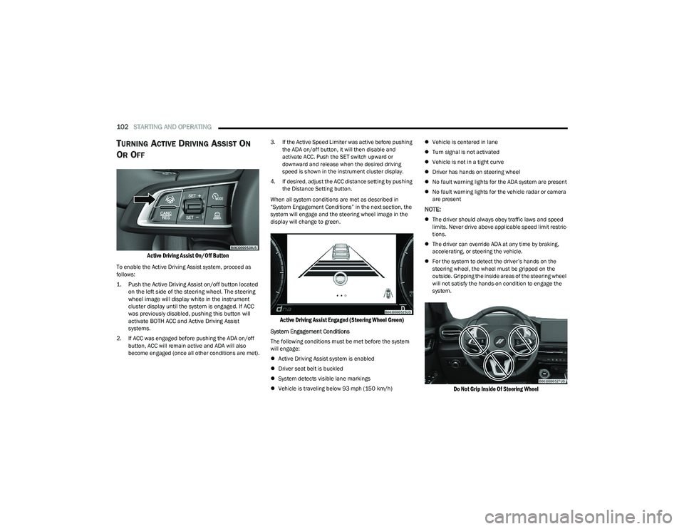
To enable the Active Driving Assist system, proceed as
follows:
1. Push the Active Driving Assist on/off button located
on the left side of the steering wheel. The steering
wheel image will display white in the instrument
cluster display until the system is engaged. If ACC
was previously disabled, pushing this button will
activate BOTH ACC and Active Driving Assist
systems.
2. If ACC was engaged before pushing the ADA on/off button, ACC will remain active and ADA will also
become engaged (once all other conditions are met). 3. If the Active Speed Limiter was active before pushing
the ADA on/off button, it will then disable and
activate ACC. Push the SET switch upward or
downward and release when the desired driving
speed is shown in the instrument cluster display.
4. If desired, adjust the ACC distance setting by pushing the Distance Setting button.
When all system conditions are met as described in
“System Engagement Conditions” in the next section, the
system will engage and the steering wheel image in the
display will change to green.
Active Driving Assist Engaged (Steering Wheel Green)
System Engagement Conditions
The following conditions must be met before the system
will engage:
Active Driving Assist system is enabled
Driver seat belt is buckled
System detects visible lane markings
Vehicle is traveling below 93 mph (150 km/h)
Vehicle is centered in lane
Turn signal is not activated
Vehicle is not in a tight curve
Driver has hands on steering wheel
No fault warning lights for the ADA system are present
No fault warning lights for the vehicle radar or camera
are present
NOTE:
The driver should always obey traffic laws and speed
limits. Never drive above applicable speed limit restric -
tions.
The driver can override ADA at any time by braking,
accelerating, or steering the vehicle.
For the system to detect the driver’s hands on the
steering wheel, the wheel must be gripped on the
outside. Gripping the inside areas of the steering wheel
will not satisfy the hands-on condition to engage the
system.
Do Not Grip Inside Of Steering Wheel
23_GG_OM_EN_USC_t.book Page 102