seats DODGE HORNET 2023 Owners Manual
[x] Cancel search | Manufacturer: DODGE, Model Year: 2023, Model line: HORNET, Model: DODGE HORNET 2023Pages: 288, PDF Size: 14.2 MB
Page 4 of 288
2
INTRODUCTION
SYMBOLS KEY ....................................................................... 8
ROLLOVER WARNING .......................................................... 8VEHICLE MODIFICATIONS/ALTERATIONS ......................... 8
SYMBOL GLOSSARY ............................................................. 9
GETTING TO KNOW YOUR VEHICLE
KEYS ....................................................................................13 Key Fobs ..................................................................... 13
SENTRY KEY ........................................................................16
IGNITION SWITCH ...............................................................16 Keyless Enter ‘n Go™ Ignition .................................... 16
REMOTE START — IF EQUIPPED ......................................18 How To Use Remote Start .......................................... 18
To Exit Remote Start Mode ....................................... 19
Remote Start Front Defrost Activation —
If Equipped .................................................................. 19
Remote Start Comfort Systems — If Equipped ......... 19
Remote Start Windshield Wiper De-Icer
Activation — If Equipped ............................................. 19
Remote Start Abort Message —
If Equipped .................................................................. 20
VEHICLE SECURITY SYSTEM — IF EQUIPPED .................20 To Arm The System .................................................... 20
To Disarm The System ............................................... 21
Volumetric/Anti-Lift Protection — If Equipped ........... 21
Security System Manual Override.............................. 21 DOORS ................................................................................. 22
Manual Door Locks......................................................22
Power Door Locks ........................................................ 22
Keyless Enter ‘n Go™ — Passive Entry ....................... 23
Automatic Door Locks —
If Equipped ................................................................... 25
Automatic Unlock Doors On Exit ................................. 25
Dead Lock Device — If Equipped ................................ 25
Child-Protection Door Lock System — Rear Doors.....25
STEERING WHEEL .............................................................. 26 Tilt/Telescoping Steering Column ..............................26
Heated Steering Wheel —
If Equipped .................................................................. 26
DRIVER MEMORY SETTINGS — IF EQUIPPED ................. 27 Programming The Memory Feature............................ 27
Memory Position Recall............................................... 27
SEATS ................................................................................... 27 Manual Adjustment (Front Seats) — If Equipped ...... 28
Manual Adjustment (Rear Seats) ............................... 28
Power Adjustment (Front Seats) — If Equipped ......... 29
Front Heated Seats — If Equipped..............................30
Front Ventilated Seats —
If Equipped ................................................................... 31
Rear Seat Armrest — If Equipped ............................... 31
Head Restraints ........................................................... 31 UCONNECT VOICE RECOGNITION QUICK
TIPS — IF EQUIPPED .......................................................... 33
Introducing Voice Recognition .................................... 33
Basic Voice Commands .............................................. 33
Get Started .................................................................. 33
Additional Information ................................................ 33
MIRRORS ............................................................................ 34 Inside Rearview Mirror ................................................ 34
Illuminated Vanity Mirrors........................................... 34
Outside Mirrors ........................................................... 35
Power Adjustment Mirrors .......................................... 35
Folding Mirrors ............................................................ 36
Heated Mirrors — If Equipped ..................................... 36
UNIVERSAL GARAGE DOOR OPENER (HOMELINK®) —
IF EQUIPPED
b
................................................................. 36
Before You Begin Programming HomeLink® ............ 36
Erasing All The HomeLink® Channels ....................... 37
Identifying Whether You Have A Rolling Code Or
Non-Rolling Code Device............................................. 37
Programming HomeLink® To A Garage Door
Opener ......................................................................... 37
Programming HomeLink® To A Miscellaneous
Device .......................................................................... 38
Reprogramming A Single HomeLink® Button ........... 38
Canadian/Gate Operator Programming .................... 38
Security ........................................................................ 39
Troubleshooting Tips ................................................... 39
23_GG_OM_EN_USC_t.book Page 2
Page 8 of 288
6
SERVICING AND MAINTENANCE
SCHEDULED SERVICING ................................................ 223
Maintenance Plan ..................................................... 224
ENGINE COMPARTMENT................................................. 226 2.0L Engine .............................................................. 226Checking Oil Level ..................................................... 227
Adding Washer Fluid ................................................ 227Maintenance-Free Battery........................................ 227Pressure Washing ..................................................... 228
VEHICLE MAINTENANCE ................................................. 228 Engine Oil................................................................... 228
Engine Oil Filter ......................................................... 228
Engine Air Cleaner Filter ........................................... 229
Air Conditioner Maintenance ................................... 229
Body Lubrication ....................................................... 230Wiper Blades ............................................................ 230
Exhaust System ........................................................ 232
Cooling System.......................................................... 233
Brake System ........................................................... 236
Automatic Transmission —
If Equipped ................................................................ 236
Fuses ......................................................................... 237
Bulb Replacement ................................................... 246
TIRES ................................................................................ 246 Tire Safety Information ............................................ 246
Tires — General Information .................................... 254
Tire Types................................................................... 257
Spare Tires — If Equipped ........................................ 258Snow Traction Devices ............................................ 259
Tire Rotation Recommendations ............................ 260 DEPARTMENT OF TRANSPORTATION UNIFORM
TIRE QUALITY GRADES .................................................. 260
Treadwear ................................................................. 260Traction Grades ........................................................ 261Temperature Grades ................................................ 261
STORING THE VEHICLE ................................................... 261
BODYWORK ...................................................................... 262 Protection From Atmospheric Agents ...................... 262Body And Underbody Maintenance ......................... 262
Preserving The Bodywork ......................................... 263
INTERIORS ....................................................................... 263 Seats And Fabric Parts ............................................. 263
Plastic And Coated Parts .......................................... 264Leather Surfaces ...................................................... 264
Glass Surfaces ......................................................... 264
TECHNICAL SPECIFICATIONS
VEHICLE IDENTIFICATION NUMBER (VIN)..................... 265
BRAKE SYSTEM .............................................................. 265
WHEEL AND TIRE TORQUE SPECIFICATIONS .............. 265 Torque Specifications ............................................... 265
FUEL REQUIREMENTS ..................................................... 266 2.0L Engine ............................................................... 266Reformulated Gasoline ........................................... 266Gasoline/Oxygenate Blends ................................... 266E-85 Usage In Non-Flex Fuel Vehicles ..................... 267CNG And LP Fuel System Modifications.................. 267
Methylcyclopentadienyl Manganese
Tricarbonyl (MMT) In Gasoline ................................. 267
Materials Added To Fuel .......................................... 267Fuel System Cautions ............................................... 267 FLUID CAPACITIES ...........................................................268
ENGINE FLUIDS AND LUBRICANTS ................................269
CHASSIS FLUIDS AND LUBRICANTS ..............................269
CUSTOMER ASSISTANCE
SUGGESTIONS FOR OBTAINING SERVICE FOR
YOUR VEHICLE ................................................................. 270 Prepare For The Appointment .................................. 270
Prepare A List ............................................................ 270Be Reasonable With Requests ................................. 270
IF YOU NEED ASSISTANCE .............................................270 Roadside Assistance ................................................. 271
FCA US LLC Customer Center ................................... 272
FCA Canada Inc. Customer Care .............................. 272
Mexico ........................................................................ 272
Puerto Rico And US Virgin Islands............................ 272
Customer Assistance For The Hearing Or
Speech Impaired (TDD/TTY) ..................................... 272
Service Contract ....................................................... 272
WARRANTY INFORMATION.............................................273
MOPAR® PARTS ..............................................................273
REPORTING SAFETY DEFECTS ......................................273 In The 50 United States And Washington, D.C........ 273
In Canada................................................................... 273
PUBLICATION ORDER FORMS .......................................274
CHANGE OF OWNERSHIP OR ADDRESS.......................274
GENERAL INFORMATION................................................. 275
23_GG_OM_EN_USC_t.book Page 6
Page 18 of 288
16GETTING TO KNOW YOUR VEHICLE
SENTRY KEY
The Sentry Key Immobilizer system prevents unauthorized
vehicle operation by disabling the engine. The system
does not need to be armed or activated. Operation is
automatic, regardless of whether the vehicle is locked or
unlocked.
The system uses a key fob, keyless push button ignition
and a Radio Frequency (RF) receiver to prevent
unauthorized vehicle operation. Therefore, only key fobs
that are programmed to the vehicle can be used to start
and operate the vehicle. The system cannot reprogram a
key fob obtained from another vehicle.
After placing the ignition in the ON/RUN position, the
Vehicle Security Light will turn on for three seconds for a
bulb check. If the light remains on after the bulb check, it
indicates that there is a problem with the electronics. In
addition, if the light begins to flash after the bulb check, it
indicates that someone attempted to start the engine with
an invalid key fob. In the event that a valid key fob is used
to start the engine but there is an issue with the vehicle
electronics, the engine will start and shut off after two
seconds.
If the Vehicle Security Light turns on during normal vehicle
operation (vehicle running for longer than 10 seconds), it
indicates that there is a fault in the electronics. Should
this occur, have the vehicle serviced as soon as possible
by an authorized dealer. All of the key fobs provided with your new vehicle have
been programmed to the vehicle electronics
Úpage 275.
NOTE:A key fob that has not been programmed is also
considered an invalid key.
IGNITION SWITCH
KEYLESS ENTER ‘N GO™ IGNITION
This feature allows the driver to operate the ignition with
the push of a button as long as the key fob is in the
passenger compartment.
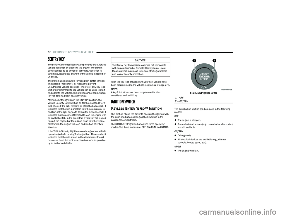
The START/STOP ignition button has three operating
modes. The three modes are: OFF, ON/RUN, and START.
START/STOP Ignition Button
The push button ignition can be placed in the following
modes:
OFF
The engine is stopped.
Some electrical devices (e.g., power locks, alarm, etc.)
are still available.
ON/RUN
Driving mode.
All electrical devices are available (e.g., climate
controls, heated seats, etc.).
START
The engine will start.
CAUTION!
The Sentry Key Immobilizer system is not compatible
with some aftermarket Remote Start systems. Use of
these systems may result in vehicle starting problems
and loss of security protection.
1 — OFF
2 — ON/RUN
23_GG_OM_EN_USC_t.book Page 16
Page 27 of 288
GETTING TO KNOW YOUR VEHICLE25
To Lock The Liftgate
With a valid Passive Entry key fob within 5 ft (1.5 m) of the
liftgate, push the Passive Entry lock button located on the
outside liftgate door handle.
NOTE:The liftgate Passive Entry lock button will lock all doors
and the liftgate Úpage 275.
AUTOMATIC DOOR LOCKS —
I
F EQUIPPED
When enabled, the door locks will lock automatically when
the vehicle's speed exceeds 12 mph (20 km/h). The auto
door lock feature is enabled or disabled within the
Uconnect system
Úpage 130.
AUTOMATIC UNLOCK DOORS ON EXIT
The doors will unlock automatically on vehicles with power
door locks if:
1. The Automatic Unlock Doors On Exit feature is
enabled.
2. All doors are closed.
3. The gear selector was not in PARK, then is placed in PARK.
4. Any door is opened.
DEAD LOCK DEVICE — IF EQUIPPED
The Dead Lock Device is a safety device that prevents the
use of the internal door handles of the vehicle and the
power door lock switch. This device prevents the doors
from opening within the passenger compartment.
The device works on all doors.
Arming The Device
The device is armed after two pushes of the lock button
on the key fob
For vehicles equipped with Passive Entry, the device
will also work by pushing the lock button on the driver’s
or passenger’s side exterior door handle
The arming of the device is indicated by three flashes of
the turn signals.
NOTE:The device does not operate if one or more doors are not
properly closed.
Disarming The Device
The device will automatically disarm by pushing the
unlock button on the key fob
By placing the ignition in the ON/RUN position
For vehicles equipped with Passive Entry, the device
will also disarm by using the driver’s or passenger’s
Passive Entry door handle to unlock and open the door
CHILD-PROTECTION DOOR LOCK
S
YSTEM — REAR DOORS
To provide a safer environment for small children riding in
the rear seats, the rear doors are equipped with a
Child-Protection Door Lock system.
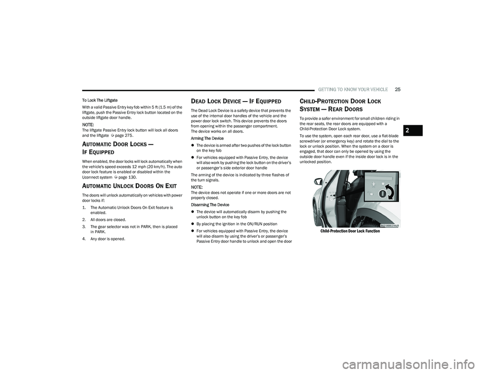
To use the system, open each rear door, use a flat-blade
screwdriver (or emergency key) and rotate the dial to the
lock or unlock position. When the system on a door is
engaged, that door can only be opened by using the
outside door handle even if the inside door lock is in the
unlocked position.
Child-Protection Door Lock Function
2
23_GG_OM_EN_USC_t.book Page 25
Page 29 of 288
GETTING TO KNOW YOUR VEHICLE27
For information on use with the Remote Start system, see Úpage 19.
DRIVER MEMORY SETTINGS — IF EQUIPPED
This feature allows the driver to save up to two different
memory profiles for easy recall through a memory switch.
Each memory profile saves desired position settings for
the following features:
Driver seat position
A set of desired radio station presets
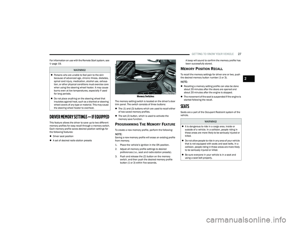
Memory Switches
The memory setting switch is located on the driver’s door
trim panel. The switch consists of three buttons:
The (1) and (3) buttons which are used to recall either
of two saved memory profiles.
The set (2) button, which is used to activate the
memory save function.
PROGRAMMING THE MEMORY FEATURE
To create a new memory profile, perform the following:
NOTE:Saving a new memory profile will erase an existing profile
from memory.
1. Place the vehicle’s ignition in the ON position.
2. Adjust all memory profile settings to desired
preferences (i.e., seat and radio station presets).
3. Push and release the (2) button on the memory switch, and then push the desired memory profile
button (1 or 3) within five seconds. A beep will sound to confirm the memory profile has
been successfully stored.
MEMORY POSITION RECALL
To recall the memory settings for driver one or two, push
the desired memory button number (1 or 3).
NOTE:
Recalling a memory setting profile can also be done
about 20 minutes after the doors are opened and
about 20 minutes after the engine is stopped.
The movement of the seat is suspended if the engine is
started following the recall.
SEATS
Seats are a part of the Occupant Restraint system of the
vehicle.
WARNING!
Persons who are unable to feel pain to the skin
because of advanced age, chronic illness, diabetes,
spinal cord injury, medication, alcohol use, exhaus -
tion, or other physical conditions must exercise care
when using the steering wheel heater. It may cause
burns even at low temperatures, especially if used
for long periods.
Do not place anything on the steering wheel that
insulates against heat, such as a blanket or steering
wheel covers of any type or material. This may cause
the steering wheel heater to overheat.
WARNING!
It is dangerous to ride in a cargo area, inside or
outside of a vehicle. In a collision, people riding in
these areas are more likely to be seriously injured or
killed.
Do not allow people to ride in any area of your vehicle
that is not equipped with seats and seat belts. In a
collision, people riding in these areas are more likely
to be seriously injured or killed.
Be sure everyone in your vehicle is in a seat and
using a seat belt properly.
2
23_GG_OM_EN_USC_t.book Page 27
Page 30 of 288
28GETTING TO KNOW YOUR VEHICLE
MANUAL ADJUSTMENT (FRONT SEATS) —
I
F EQUIPPED
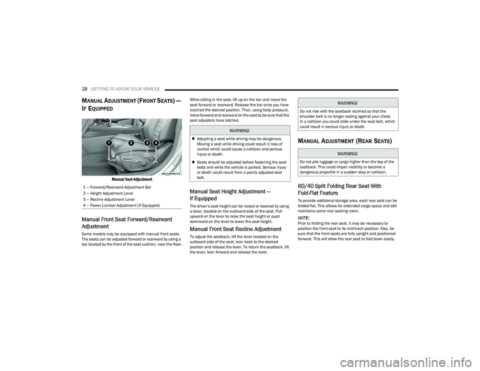
Manual Seat Adjustment
Manual Front Seat Forward/Rearward
Adjustment
Some models may be equipped with manual front seats.
The seats can be adjusted forward or rearward by using a
bar located by the front of the seat cushion, near the floor. While sitting in the seat, lift up on the bar and move the
seat forward or rearward. Release the bar once you have
reached the desired position. Then, using body pressure,
move forward and rearward on the seat to be sure that the
seat adjusters have latched.
Manual Seat Height Adjustment —
If Equipped
The driver’s seat height can be raised or lowered by using
a lever, located on the outboard side of the seat. Pull
upward on the lever to raise the seat height or push
downward on the lever to lower the seat height.
Manual Front Seat Recline Adjustment
To adjust the seatback, lift the lever located on the
outboard side of the seat, lean back to the desired
position and release the lever. To return the seatback, lift
the lever, lean forward and release the lever.
MANUAL ADJUSTMENT (REAR SEATS)
60/40 Split Folding Rear Seat With
Fold-Flat Feature
To provide additional storage area, each rear seat can be
folded flat. This allows for extended cargo space and still
maintains some rear seating room.
NOTE:Prior to folding the rear seat, it may be necessary to
position the front seat to its mid-track position. Also, be
sure that the front seats are fully upright and positioned
forward. This will allow the rear seat to fold down easily.
1 — Forward/Rearward Adjustment Bar
2 — Height Adjustment Lever
3 — Recline Adjustment Lever
4 — Power Lumbar Adjustment (If Equipped)
WARNING!
Adjusting a seat while driving may be dangerous.
Moving a seat while driving could result in loss of
control which could cause a collision and serious
injury or death.
Seats should be adjusted before fastening the seat
belts and while the vehicle is parked. Serious injury
or death could result from a poorly adjusted seat
belt.
WARNING!
Do not ride with the seatback reclined so that the
shoulder belt is no longer resting against your chest.
In a collision you could slide under the seat belt, which
could result in serious injury or death.
WARNING!
Do not pile luggage or cargo higher than the top of the
seatback. This could impair visibility or become a
dangerous projectile in a sudden stop or collision.
23_GG_OM_EN_USC_t.book Page 28
Page 31 of 288
GETTING TO KNOW YOUR VEHICLE29
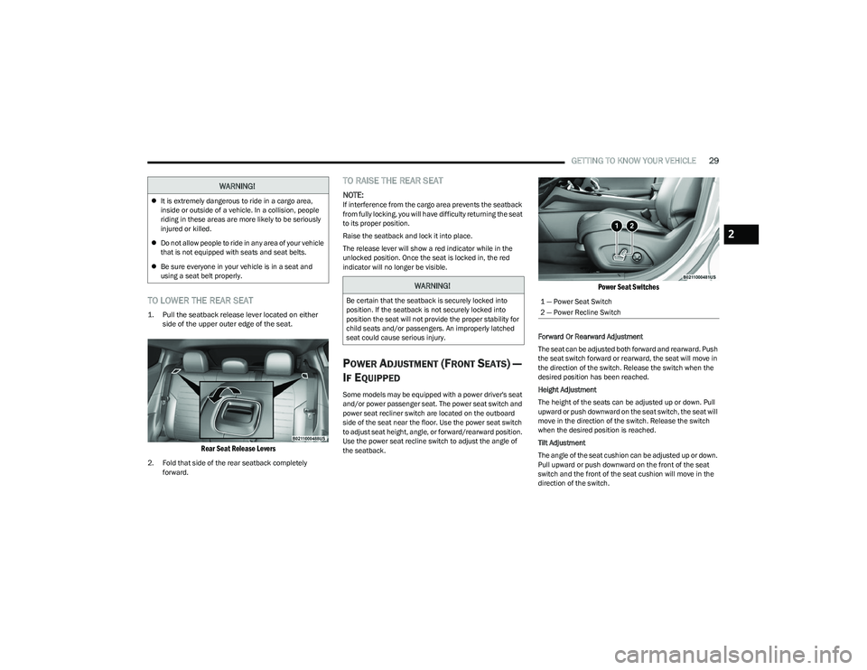
TO LOWER THE REAR SEAT
1. Pull the seatback release lever located on either
side of the upper outer edge of the seat.
Rear Seat Release Levers
2. Fold that side of the rear seatback completely forward.
TO RAISE THE REAR SEAT
NOTE:If interference from the cargo area prevents the seatback
from fully locking, you will have difficulty returning the seat
to its proper position.
Raise the seatback and lock it into place.
The release lever will show a red indicator while in the
unlocked position. Once the seat is locked in, the red
indicator will no longer be visible.
POWER ADJUSTMENT (FRONT SEATS) —
I
F EQUIPPED
Some models may be equipped with a power driver's seat
and/or power passenger seat. The power seat switch and
power seat recliner switch are located on the outboard
side of the seat near the floor. Use the power seat switch
to adjust seat height, angle, or forward/rearward position.
Use the power seat recline switch to adjust the angle of
the seatback.
Power Seat Switches
Forward Or Rearward Adjustment
The seat can be adjusted both forward and rearward. Push
the seat switch forward or rearward, the seat will move in
the direction of the switch. Release the switch when the
desired position has been reached.
Height Adjustment
The height of the seats can be adjusted up or down. Pull
upward or push downward on the seat switch, the seat will
move in the direction of the switch. Release the switch
when the desired position is reached.
Tilt Adjustment
The angle of the seat cushion can be adjusted up or down.
Pull upward or push downward on the front of the seat
switch and the front of the seat cushion will move in the
direction of the switch.
WARNING!
It is extremely dangerous to ride in a cargo area,
inside or outside of a vehicle. In a collision, people
riding in these areas are more likely to be seriously
injured or killed.
Do not allow people to ride in any area of your vehicle
that is not equipped with seats and seat belts.
Be sure everyone in your vehicle is in a seat and
using a seat belt properly.
WARNING!
Be certain that the seatback is securely locked into
position. If the seatback is not securely locked into
position the seat will not provide the proper stability for
child seats and/or passengers. An improperly latched
seat could cause serious injury.1 — Power Seat Switch
2 — Power Recline Switch
2
23_GG_OM_EN_USC_t.book Page 29
Page 32 of 288
30GETTING TO KNOW YOUR VEHICLE
Reclining The Seatback Forward Or
Rearward
The seatback can be reclined both forward and rearward.
Push the seat recliner switch forward or rearward. The
seatback will move in the direction of the switch. Release
the switch when the desired position has been reached.
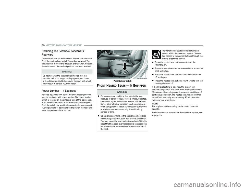
Power Lumbar — If Equipped
Vehicles equipped with power driver or passenger seats
may be equipped with power lumbar. The power lumbar
switch is located on the outboard side of the power seat.
Push the switch forward to increase the lumbar support.
Push the switch rearward to decrease the lumbar support.
Pushing upward or downward on the switch will raise and
lower the position of the support.
Power Lumbar Switch
FRONT HEATED SEATS — IF EQUIPPED
The front heated seats control buttons are
located within the Uconnect system. You can
gain access to the control buttons through the
climate or controls screen.
Press the heated seat button once to turn the
HI setting on.
Press the heated seat button a second time to turn the
MED setting on.
Press the heated seat button a third time to turn the
LO setting on.
Press the heated seat button a fourth time to turn the
heating elements off.
If the HI level setting is selected, the system will
automatically switch to a lower level after approximately
15 minutes (depending on environmental conditions) of
continuous operation. The heated seat feature will then
turn off automatically approximately 45 minutes after
switching to a lower level.
NOTE:The engine must be running for the heated seats to
operate.
For information on use with the Remote Start system, see
Úpage 19.
WARNING!
Do not ride with the seatback reclined so that the
shoulder belt is no longer resting against your chest.
In a collision you could slide under the seat belt, which
could result in serious injury or death.
WARNING!
Persons who are unable to feel pain to the skin
because of advanced age, chronic illness, diabetes,
spinal cord injury, medication, alcohol use, exhaus -
tion or other physical condition must exercise care
when using the seat heater. It may cause burns even
at low temperatures, especially if used for long
periods of time.
Do not place anything on the seat or seatback that
insulates against heat, such as a blanket or cushion.
This may cause the seat heater to overheat. Sitting in
a seat that has been overheated could cause serious
burns due to the increased surface temperature of
the seat.
23_GG_OM_EN_USC_t.book Page 30
Page 33 of 288
GETTING TO KNOW YOUR VEHICLE31
FRONT VENTILATED SEATS —
I
F EQUIPPED
Located in the seat cushion and seat back are
fans that draw the air from the passenger
compartment and move air through fine
perforations in the seat cover to help keep the
driver and front passenger cooler in higher ambient
temperatures. The fans operate at three speeds:
HI, MED, and LO.
The front ventilated seats control buttons are located
within the Uconnect system. You can gain access to the
control buttons through the climate screen or the controls
screen.
Press the ventilated seat button once to choose HI.
Press the ventilated seat button a second time to
choose MED.
Press the ventilated seat button a third time to
choose LO.
Press the ventilated seat button a fourth time to turn
the ventilated seat off.
NOTE:The engine must be running for the ventilated seats to
operate.
For information on use with the Remote Start system, see
Úpage 19.
REAR SEAT ARMREST — IF EQUIPPED
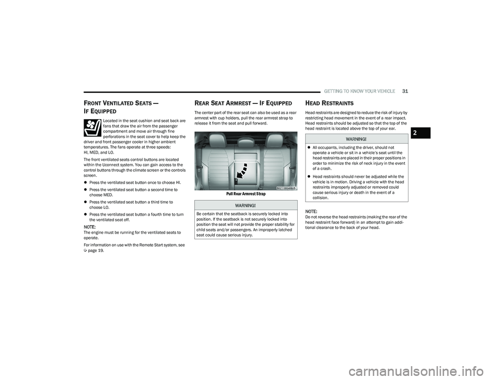
The center part of the rear seat can also be used as a rear
armrest with cup holders, pull the rear armrest strap to
release it from the seat and pull forward.
Pull Rear Armrest Strap
HEAD RESTRAINTS
Head restraints are designed to reduce the risk of injury by
restricting head movement in the event of a rear impact.
Head restraints should be adjusted so that the top of the
head restraint is located above the top of your ear.
NOTE:Do not reverse the head restraints (making the rear of the
head restraint face forward) in an attempt to gain addi -
tional clearance to the back of your head.
WARNING!
Be certain that the seatback is securely locked into
position. If the seatback is not securely locked into
position the seat will not provide the proper stability for
child seats and/or passengers. An improperly latched
seat could cause serious injury.
WARNING!
All occupants, including the driver, should not
operate a vehicle or sit in a vehicle’s seat until the
head restraints are placed in their proper positions in
order to minimize the risk of neck injury in the event
of a crash.
Head restraints should never be adjusted while the
vehicle is in motion. Driving a vehicle with the head
restraints improperly adjusted or removed could
cause serious injury or death in the event of a
collision.
2
23_GG_OM_EN_USC_t.book Page 31
Page 51 of 288
GETTING TO KNOW YOUR VEHICLE49
Combine Modes
Dual Level Combination
Front Defrost and Panel Mode
Tri-Level Combination
Front Defrost, Panel Mode, and Floor Mode
Climate Control OFF Button
Press and release this button on the
touchscreen, or push and release the
button on the faceplate to turn the
Climate Control ON/OFF.
AUTOMATIC TEMPERATURE
CONTROL (ATC)
Automatic Operation
1. Push the AUTO button on the faceplate, or the
AUTO button on the touchscreen (if equipped) on the
Automatic Temperature Control (ATC) Panel.
2. Next, adjust the temperature you would like the system to maintain by adjusting the temperature
control buttons. Once the desired temperature is
displayed, the system achieves and automatically
maintains that comfort level.
3. When the system is set up for your comfort level, it is not necessary to change the settings. You experience
the greatest efficiency by simply allowing the system
to function automatically.
NOTE:
It is not necessary to move the temperature settings for
cold or hot vehicles. The system automatically adjusts
the temperature, mode, and blower speed to provide
comfort as quickly as possible.
The temperature can be displayed in US or Metric units
by selecting the US/Metric customer-programmable
feature.
To provide you with maximum comfort in the Automatic
mode during cold start-ups, the blower fan remains on low
until the engine warms up. The blower increases in speed
and transition into Auto mode.
Manual Operation Override
This system offers a full complement of manual override
features. The AUTO symbol in the front ATC display will be
turned off when the system is being used in the manual
mode.
CLIMATE VOICE COMMANDS
Adjust vehicle temperatures hands-free and keep
everyone comfortable while you keep moving ahead.
Push the VR button on the steering wheel. After the beep,
say one of the following commands:
“Set the driver temperature to 70 degrees ”
“Set the passenger temperature to 70 degrees ”
Did You Know: Voice Command for Climate may only be
used to adjust the interior temperature of your vehicle.
Voice Command will not work to adjust the heated seats
or steering wheel if equipped.
OPERATING TIPS
Refer to the chart at the end of this section for suggested
control settings for various weather conditions.
Summer Operation
The engine cooling system must be protected with a
high-quality antifreeze coolant to provide proper corrosion
protection and to protect against engine overheating.
OAT coolant (conforming to MS.90032) is recommended.
The driver or front passenger can combine
two or three of the modes described by
selecting them individually on the climate
control screen. Combine modes by
pressing each icon on the touchscreen.
2
23_GG_OM_EN_USC_t.book Page 49