sport mode DODGE HORNET 2023 Owners Manual
[x] Cancel search | Manufacturer: DODGE, Model Year: 2023, Model line: HORNET, Model: DODGE HORNET 2023Pages: 288, PDF Size: 14.2 MB
Page 6 of 288
4
STARTING AND OPERATING
STARTING THE ENGINE ......................................................80
Normal Starting ........................................................... 80
Cold Weather Operation
(Below –22°F Or −30°C) .......................................... 81
Extended Park Starting............................................... 81
After Starting — Warming Up The Engine .................. 81
If Engine Fails To Start ............................................... 81
Stopping The Engine ................................................... 82
ENGINE BREAK-IN RECOMMENDATIONS .......................82
PARK BRAKE ....................................................................... 82 Electric Park Brake (EPB) .......................................... 82
AUTOMATIC TRANSMISSION .............................................85 Ignition Park Interlock................................................. 86
Brake/Transmission Shift Interlock (BTSI)
System ......................................................................... 86
9-Speed Automatic Transmission ............................. 86
ALL-WHEEL DRIVE (AWD) ..................................................88
SPORT MODE — IF EQUIPPED ...........................................88
POWER STEERING ..............................................................88
STOP/START SYSTEM — IF EQUIPPED.............................89 Autostop Mode ............................................................ 89
Possible Reasons The Engine Does Not Autostop.... 89
To Start The Engine While In Autostop Mode............ 90
To Manually Turn Off The Stop/Start System ........... 90
To Manually Turn On The Stop/Start System............ 90
System Malfunction .................................................... 90 ACTIVE SPEED LIMITER — IF EQUIPPED .......................... 90
Activation...................................................................... 91
Exceeding The Set Speed ........................................... 91
Deactivation ................................................................. 91
INTELLIGENT SPEED ASSIST (ISA) —
IF EQUIPPED ........................................................................ 91 Activation...................................................................... 92
Sign Capture Modes .................................................... 92
Exceeding The Set Speed ........................................... 92
Deactivation ................................................................. 92
CRUISE CONTROL SYSTEMS ............................................. 92 Adaptive Cruise Control (ACC)..................................... 92
TRAFFIC SIGN RECOGNITION —
IF EQUIPPED ........................................................................ 99 Activation/Deactivation ............................................... 99
Traffic Sign Recognition Modes .................................. 99
Indications On The Display....................................... 100
INTELLIGENT ADAPTIVE CRUISE CONTROL —
IF EQUIPPED ..................................................................... 100 Activation/Deactivation ............................................ 100
ACTIVE DRIVING ASSIST SYSTEM —
IF EQUIPPED ..................................................................... 101 Operation................................................................... 101
Turning Active Driving Assist On Or Off ................... 102
Indications On The Display....................................... 103
Minimum Risk Maneuver ......................................... 104
System Status ........................................................... 104
System Operation/Limitations................................. 104 PARKSENSE FRONT/REAR PARK ASSIST SYSTEM —
IF EQUIPPED ....................................................................105
ParkSense Sensors ................................................... 105
ParkSense Warning Display...................................... 105ParkSense Display .................................................... 105
Enabling And Disabling ParkSense .......................... 106
Service The ParkSense Park Assist System ............ 106
Cleaning The ParkSense System ............................. 106
ParkSense System Usage Precautions .................... 106
Side Distance Warning (SDW) System..................... 107
PARKSENSE ACTIVE PARK ASSIST SYSTEM —
IF EQUIPPED......................................................................108 Enabling And Disabling The ParkSense Active
Park Assist System .................................................... 109
Parallel/Perpendicular Parking Space Assistance
Operation ................................................................... 110Exiting The Parking Space ........................................ 112
LANESENSE — IF EQUIPPED .......................................... 113 LaneSense Operation ............................................... 113Turning LaneSense On Or Off ................................... 114
LaneSense Warning Message .................................. 114
Changing LaneSense Status .................................... 116
PARKVIEW REAR BACK UP CAMERA ............................ 116
SURROUND VIEW CAMERA SYSTEM —
IF EQUIPPED......................................................................117
REFUELING THE VEHICLE ................................................119
VEHICLE LOADING ...........................................................120 Certification Label ..................................................... 120
23_GG_OM_EN_USC_t.book Page 4
Page 7 of 288
5
TRAILER TOWING............................................................. 121Common Towing Definitions .................................... 121
Trailer Towing Weights
(Maximum Trailer Weight Ratings) .......................... 122Trailer And Tongue Weight ....................................... 123
Towing Requirements .............................................. 123
Towing Tips ............................................................... 125
RECREATIONAL TOWING (BEHIND MOTORHOME) .... 126 Towing This Vehicle Behind Another Vehicle .......... 126
Recreational Towing ................................................. 127
DRIVING TIPS ................................................................... 127 Driving On Slippery Surfaces.................................... 127
Driving Through Water ............................................. 128
MULTIMEDIA
UCONNECT SYSTEMS ..................................................... 129
CYBERSECURITY ............................................................. 129
UCONNECT SETTINGS ..................................................... 130Customer Programmable Features ......................... 130
STEERING WHEEL AUDIO CONTROLS —
IF EQUIPPED .................................................................... 150 Steering Wheel Rotary Control ................................. 150Controls on Central Tunnel....................................... 151
MY CAR ............................................................................. 151
PERFORMANCE PAGES .................................................. 152 Technical Gauges...................................................... 152Consumption History ................................................ 152Accessory Gauges ..................................................... 153
RADIO OPERATION AND MOBILE PHONES .................. 153 Regulatory And Safety Information .......................... 153
SAFETY
SAFETY FEATURES .......................................................... 154Anti-Lock Brake System (ABS) ................................ 154
Electronic Brake Control (EBC) System .................. 155
AUXILIARY DRIVING SYSTEMS ...................................... 159 Blind Spot Monitoring (BSM) —
If Equipped ................................................................ 159Forward Collision Warning (FCW)
With Mitigation — If Equipped .................................. 162
Tire Pressure Monitoring System (TPMS) ............... 165
OCCUPANT RESTRAINT SYSTEMS ............................... 168 Occupant Restraint Systems Features ................... 168
Important Safety Precautions .................................. 168
Seat Belt Systems .................................................... 169
Supplemental Restraint Systems (SRS).................. 175
Child Restraints ........................................................ 188
SAFETY TIPS .................................................................... 199 Transporting Passengers ......................................... 199
Transporting Pets .................................................... 199
Connected Vehicles .................................................. 199Safety Checks You Should Make Inside
The Vehicle ............................................................... 200Periodic Safety Checks You Should Make Outside
The Vehicle ................................................................ 201Exhaust Gas .............................................................. 202
Carbon Monoxide Warnings ..................................... 202
IN CASE OF EMERGENCY
HAZARD WARNING FLASHERS ......................................203
SOS SYSTEM — IF EQUIPPED.......................................... 203
JACKING AND TIRE CHANGING —
IF EQUIPPED
b
...............................................................206
Preparations For Jacking ......................................... 206
Jack And Tools Location/Spare Tire Stowage —
If Equipped................................................................. 207
Jacking Instructions ................................................. 208
TIRE INFLATOR KIT — IF EQUIPPED
b
........................211
Description................................................................. 211
Inflation Procedure.................................................... 212
Checking And Restoring Tire Pressure..................... 214
Sealant Cartridge Replacement ............................... 214
JUMP STARTING ...............................................................215 Preparations For Jump Start..................................... 215
Jump Starting Procedure .......................................... 216
REFUELING IN EMERGENCY ........................................... 217
IF YOUR ENGINE OVERHEATS ........................................218
GEAR SELECTOR OVERRIDE .......................................... 218
FREEING A STUCK VEHICLE ........................................... 219
TOWING A DISABLED VEHICLE.......................................220 Without The Key Fob ................................................. 221
All-Wheel Drive (AWD) Models ................................. 221
Tow Eye — If Equipped .............................................. 221
ENHANCED ACCIDENT RESPONSE
SYSTEM (EARS) ...............................................................222
EVENT DATA RECORDER (EDR)......................................222
23_GG_OM_EN_USC_t.book Page 5
Page 14 of 288
12
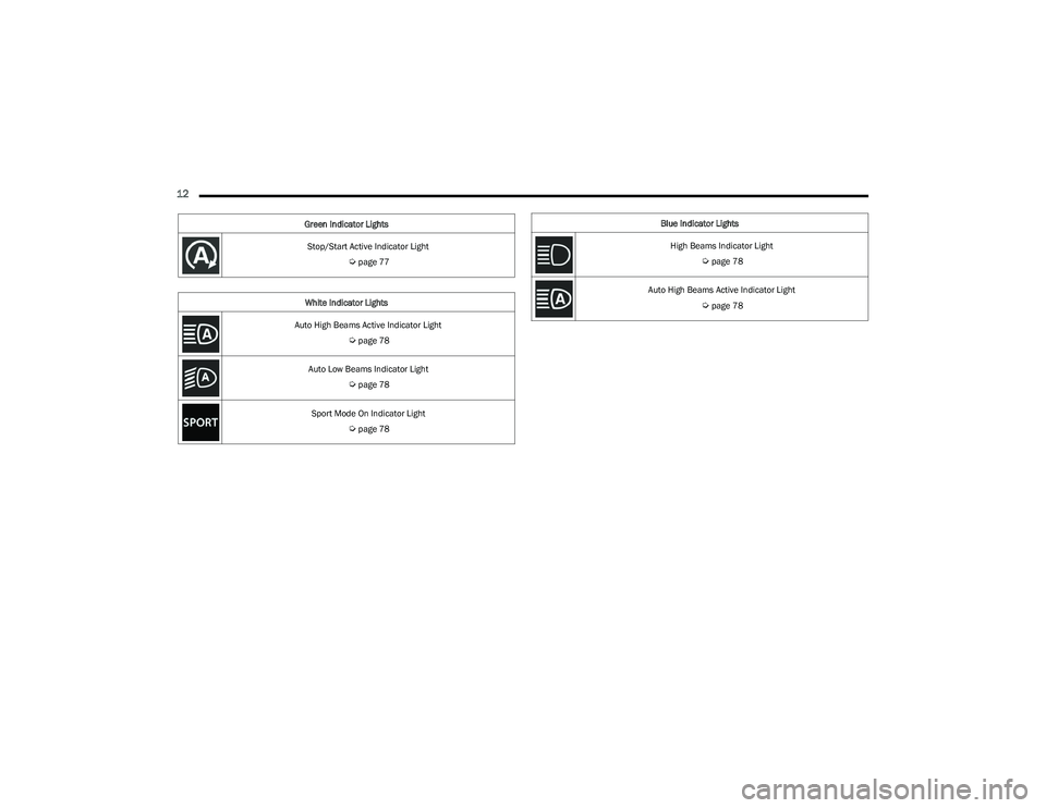
Stop/Start Active Indicator Light
Úpage 77
White Indicator Lights
Auto High Beams Active Indicator Light
Úpage 78
Auto Low Beams Indicator Light
Úpage 78
Sport Mode On Indicator Light
Úpage 78
Green Indicator Lights
Blue Indicator Lights
High Beams Indicator Light
Úpage 78
Auto High Beams Active Indicator Light
Úpage 78
23_GG_OM_EN_USC_t.book Page 12
Page 80 of 288
78GETTING TO KNOW YOUR INSTRUMENT PANEL
WHITE INDICATOR LIGHTS
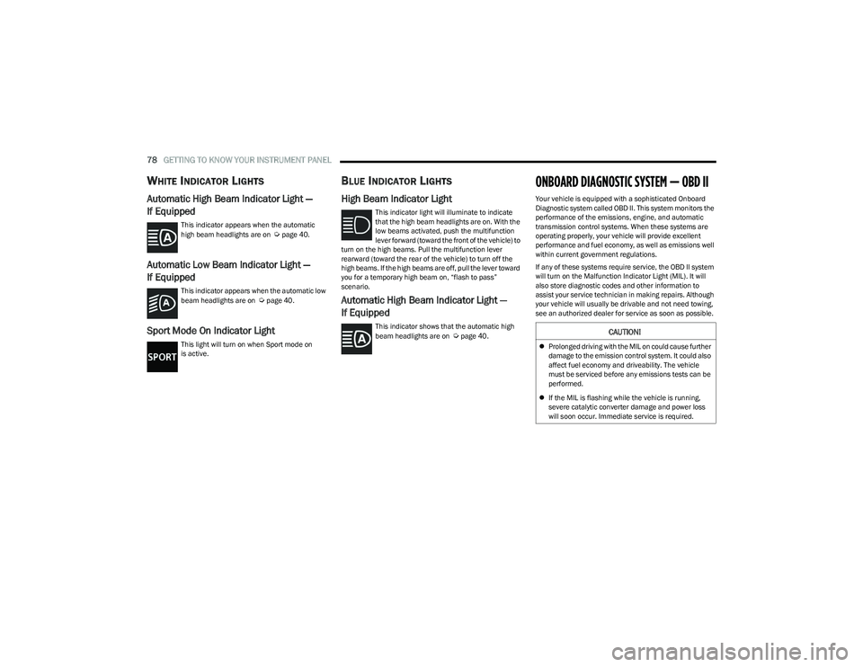
Automatic High Beam Indicator Light —
If Equipped
This indicator appears when the automatic
high beam headlights are on Úpage 40.
Automatic Low Beam Indicator Light —
If Equipped
This indicator appears when the automatic low
beam headlights are on Úpage 40.
Sport Mode On Indicator Light
This light will turn on when Sport mode on
is active.
BLUE INDICATOR LIGHTS
High Beam Indicator Light
This indicator light will illuminate to indicate
that the high beam headlights are on. With the
low beams activated, push the multifunction
lever forward (toward the front of the vehicle) to
turn on the high beams. Pull the multifunction lever
rearward (toward the rear of the vehicle) to turn off the
high beams. If the high beams are off, pull the lever toward
you for a temporary high beam on, “flash to pass”
scenario.
Automatic High Beam Indicator Light —
If Equipped
This indicator shows that the automatic high
beam headlights are on Úpage 40.
ONBOARD DIAGNOSTIC SYSTEM — OBD II
Your vehicle is equipped with a sophisticated Onboard
Diagnostic system called OBD II. This system monitors the
performance of the emissions, engine, and automatic
transmission control systems. When these systems are
operating properly, your vehicle will provide excellent
performance and fuel economy, as well as emissions well
within current government regulations.
If any of these systems require service, the OBD II system
will turn on the Malfunction Indicator Light (MIL). It will
also store diagnostic codes and other information to
assist your service technician in making repairs. Although
your vehicle will usually be drivable and not need towing,
see an authorized dealer for service as soon as possible.
CAUTION!
Prolonged driving with the MIL on could cause further
damage to the emission control system. It could also
affect fuel economy and driveability. The vehicle
must be serviced before any emissions tests can be
performed.
If the MIL is flashing while the vehicle is running,
severe catalytic converter damage and power loss
will soon occur. Immediate service is required.
23_GG_OM_EN_USC_t.book Page 78
Page 90 of 288
88STARTING AND OPERATING
In the event of a momentary problem, the transmission
can be reset to regain all forward gears by performing the
following steps:
1. Stop the vehicle.
2. Shift the transmission into PARK (P), if possible. If
not, shift the transmission to NEUTRAL.
3. Push and hold the ignition until the engine turns off.
4. Wait approximately 30 seconds.
5. Restart the engine.
6. Shift into the desired gear range. If the problem is no longer detected, the transmission will return to
normal operation.
NOTE:Even if the transmission can be reset, we recommend that
you visit an authorized dealer at your earliest possible
convenience. An authorized dealer has diagnostic
equipment to assess the condition of your transmission.
If the transmission cannot be reset, authorized dealer
service is required.
TORQUE CONVERTER CLUTCH
A feature designed to improve fuel economy has been
included in the automatic transmission on your vehicle.
A clutch within the torque converter engages
automatically at calibrated speeds. This may result in a
slightly different feeling or response during normal
operation in the upper gears. When the vehicle speed
drops or during some accelerations, the clutch
automatically disengages.
NOTE:The torque converter clutch will not engage until the
engine and/or transmission is warm (usually after 1 to
3 miles [2 to 5 km] of driving). Because the engine speed
is higher when the torque converter clutch is not engaged,
it may seem as if the transmission is not shifting properly
when the vehicle is cold. This is normal. The torque
converter clutch will function normally once the powertrain
is sufficiently warm.
ALL-WHEEL DRIVE (AWD)
This feature provides on-demand All-Wheel Drive (AWD).
The system is automatic with no driver inputs or additional
driving skills required. Under normal driving conditions,
the front wheels provide most of the traction. If the front
wheels begin to lose traction, power is shifted
automatically to the rear wheels. The greater the front
wheel traction loss, the greater the power transfer to the
rear wheels.
Additionally, on dry pavement under heavy throttle input
(where one may have no wheel spin), torque will be sent to
the rear in a preemptive effort to improve vehicle launch
and performance characteristics.
SPORT MODE — IF EQUIPPED
Your vehicle is equipped with a SPORT Mode feature. The
engine, transmission, and steering systems are all set to
their SPORT settings. SPORT Mode will provide improved
throttle response and modified transmission shift points
for an enhanced driving experience, as well as greater
amount of steering feel.
This mode may be activated and deactivated by pushing
the SPORT button on the steering wheel. For PHEV
versions the SPORT button is located below the STOP/
START button.
POWER STEERING
The electric power steering system will provide increased
vehicle response and ease of maneuverability. The electric
power steering system adapts to different driving conditions.
If the “SERVICE POWER STEERING” or “POWER
STEERING ASSIST OFF - SERVICE SYSTEM”
message and a steering wheel icon display on
the instrument cluster, it indicates that the
vehicle needs service. It may be necessary to perform the
recalibration maneuver by turning the steering wheel from
full left position to full right position. If the problem is still
present, take the vehicle to an authorized dealer for
service. It is likely the vehicle has lost power steering
assistance
Úpage 66.
CAUTION!
All wheels must have the same size and type tires.
Unequal tire sizes must not be used. Unequal tire size
may cause failure of the power transfer unit.
WARNING!
Continued operation with reduced assist could pose a
safety risk to yourself and others. Service should be
obtained as soon as possible.
23_GG_OM_EN_USC_t.book Page 88
Page 153 of 288
MULTIMEDIA151
CON TR O LS O N CEN TR AL TUN NEL
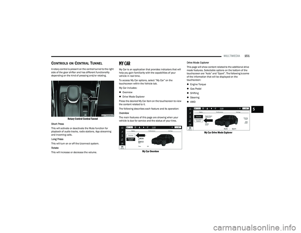
A rotary control is present on the central tunnel to the right
side of the gear shifter and has different functionality
depending on the kind of pressing and/or rotating.
Rotary Control Central Tunnel
Short Press
This will activate or deactivate the Mute function for
playback of audio tracks, radio stations, App streaming
and incoming calls.
Long Press
This will turn on or off the Uconnect system.
Rotate
This will increase or decrease the volume.
MY CAR
My Car is an application that provides indicators that will
help you gain familiarity with the capabilities of your
vehicle in real time.
To access My Car options, select “My Car” on the
touchscreen within the Vehicle tab.
My Car includes:
Overview
Drive Mode Explorer
Press the desired My Car item on the touchscreen to view
the content related to it.
The following describes each feature and its operation:
Overview
The main features of this page are showing when your
vehicle is due for service and the status of your tires.
My Car Overview
Drive Mode Explorer
This page will show content related to the additional drive
mode features. Selectable options on the bottom of the
touchscreen are “Auto” and “Sport”. The following is some
of the information that will be displayed on the
touchscreen:
Engine Torque
Gas Pedal
Shifting
Steering
AWD
My Car Drive Mode Explorer
5
23_GG_OM_EN_USC_t.book Page 151
Page 159 of 288
SAFETY157
Full Off
To enter the “Full Off” mode, push the Sport Mode button
and then hold the ESC OFF button for two seconds while
the vehicle is stopped with the engine running. After two
seconds, a chime will sound, the ESC OFF Indicator Light
will illuminate, and the “ESC OFF” message will display in
the instrument cluster. To turn ESC on again, momentarily
push the ESC OFF button.ESC Activation/Malfunction Indicator Light
And ESC OFF Indicator Light
The ESC Activation/Malfunction Indicator Light
in the instrument cluster will come on when the
ignition is placed in the ON mode. It should go
out with the engine running. If the ESC
Activation/Malfunction Indicator Light comes on
continuously with the engine running, a malfunction has
been detected in the ESC system. If this light remains on
after several ignition cycles, and the vehicle has been
driven several miles (km) at speeds greater than 30 mph
(48 km/h), see an authorized dealer as soon as possible
to have the problem diagnosed and corrected.
The ESC Activation/Malfunction Indicator Light starts to
flash as soon as the tires lose traction and the ESC system
becomes active. The ESC Activation/Malfunction Indicator
Light also flashes when Traction Control System (TCS) is
active. If the ESC Activation/Malfunction Indicator Light
begins to flash during acceleration, ease up on the
accelerator and apply as little throttle as possible. Be sure
to adapt your speed and driving to the prevailing road
conditions.
The ESC OFF Indicator Light indicates the
customer has elected to have the Electronic
Stability Control (ESC) in a reduced mode.
NOTE:
The ESC Activation/Malfunction Indicator Light and the
ESC OFF Indicator Light come on momentarily each
time the ignition is placed in the ON/RUN position.
Each time the ignition is placed in the ON/RUN posi -
tion, the ESC system will be on even if it was turned off
previously.
The ESC system will make buzzing or clicking sounds
when it is active. This is normal; the sounds will stop
when ESC becomes inactive following the maneuver
that caused the ESC activation.
Emergency Stop Signal (ESS) —
If Equipped
The ESS activates the hazard lights at a faster than normal
speed when heavy brake pressure is applied. ESS will only
activate when the speed is above 31 mph (50 km/h). The
ESS operates independently of other lamps, and will turn
on and off automatically. This indicates to others that the
vehicle is stopping quickly.
NOTE:
A warning light will illuminate within the instrument
cluster to inform the driver that the ESS feature has
been activated.
When towing a trailer, ESS will also activate the rear
indicator lights of the trailer.
WARNING!
In the ESC “Full Off” mode, the engine torque reduc -
tion and stability features are disabled. Therefore,
enhanced vehicle stability offered by the ESC system
is unavailable. In an emergency evasive maneuver,
the ESC system will not engage to assist in main -
taining stability. ESC “Full Off” mode is intended for
off-highway or off-road use only.
With the ESC switched off, the enhanced vehicle
stability offered by ESC is unavailable. In an
emergency evasive maneuver, the ESC system
will not engage to assist in maintaining stability.
ESC “Full Off” mode is only intended for off-highway
or off-road use.
The Electronic Stability Control (ESC) cannot prevent
the natural laws of physics from acting on the
vehicle, nor can it increase the traction afforded by
prevailing road conditions. ESC cannot prevent all
accidents, including those resulting from excessive
speed in turns, driving on very slippery surfaces, or
hydroplaning. ESC also cannot prevent collisions.
6
23_GG_OM_EN_USC_t.book Page 157
Page 161 of 288
SAFETY159
AUXILIARY DRIVING SYSTEMS
BLIND SPOT MONITORING (BSM) —
I
F EQUIPPED
The BSM system uses two radar sensors, located inside
the rear fascia/bumper, to detect highway licensable
vehicles (automobiles, trucks, motorcycles, etc.) that
enter the blind spot zones from the rear/front/side of
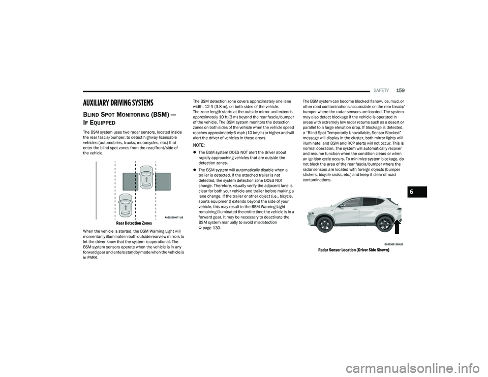
the vehicle.
Rear Detection Zones
When the vehicle is started, the BSM Warning Light will
momentarily illuminate in both outside rearview mirrors to
let the driver know that the system is operational. The
BSM system sensors operate when the vehicle is in any
forward gear and enters standby mode when the vehicle is
in PARK. The BSM detection zone covers approximately one lane
width, 12 ft (3.8 m), on both sides of the vehicle.
The zone length starts at the outside mirror and extends
approximately 10 ft (3 m) beyond the rear fascia/bumper
of the vehicle. The BSM system monitors the detection
zones on both sides of the vehicle when the vehicle speed
reaches approximately 6 mph (10 km/h) or higher and will
alert the driver of vehicles in these areas.
NOTE:
The BSM system DOES NOT alert the driver about
rapidly approaching vehicles that are outside the
detection zones.
The BSM system will automatically disable when a
trailer is detected. If the attached trailer is not
detected, the system detection zone DOES NOT
change. Therefore, visually verify the adjacent lane is
clear for both your vehicle and trailer before making a
lane change. If the trailer or other object (i.e., bicycle,
sports equipment) extends beyond the side of your
vehicle, this may result in the BSM Warning Light
remaining illuminated the entire time the vehicle is in a
forward gear. It may be necessary to deactivate the
BSM system manually to avoid misdetection
Úpage 130. The BSM system can become blocked if snow, ice, mud, or
other road contaminations accumulate on the rear fascia/
bumper where the radar sensors are located. The system
may also detect blockage if the vehicle is operated in
areas with extremely low radar returns such as a desert or
parallel to a large elevation drop. If blockage is detected,
a “Blind Spot Temporarily Unavailable, Sensor Blocked”
message will display in the cluster, both mirror lights will
illuminate, and BSM and RCP alerts will not occur. This is
normal operation. The system will automatically recover
and resume function when the condition clears or when
an ignition cycle occurs. To minimize system blockage, do
not block the area of the rear fascia/bumper where the
radar sensors are located with foreign objects (bumper
stickers, bicycle racks, etc.) and keep it clear of road
contaminations.
Radar Sensor Location (Driver Side Shown)
6
23_GG_OM_EN_USC_t.book Page 159
Page 170 of 288
168SAFETY
To reactivate the TPMS, replace all four wheel and tire
assemblies (road tires) with tires equipped with TPMS
sensors. Then, drive the vehicle for up to 20 minutes
above 15 mph (24 km/h). The TPMS will chime, the Tire
Pressure Monitoring System Warning Light will flash on
and off for 75 seconds and then turn off. The instrument
cluster will display the “SERVICE TPM SYSTEM” message
and then display pressure values in place of the dashes.
On the next ignition cycle the "SERVICE TPM SYSTEM"
message will no longer be displayed as long as no system
fault exists.
OCCUPANT RESTRAINT SYSTEMS
Some of the most important safety features in your vehicle
are the restraint systems:
OCCUPANT RESTRAINT SYSTEMS
F
EATURES
Seat Belt Systems
Supplemental Restraint Systems (SRS) Air Bags
Child Restraints
Some of the safety features described in this section may
be standard equipment on some models, or may be
optional equipment on others. If you are not sure, ask an
authorized dealer.
IMPORTANT SAFETY PRECAUTIONS
Please pay close attention to the information in this
section. It tells you how to use your restraint system
properly, to keep you and your passengers as safe as
possible.
Here are some simple steps you can take to minimize the
risk of harm from a deploying air bag:
1. Children 12 years old and under should always ride buckled up in the rear seat of a vehicle with a rear
seat.
2. A child who is not big enough to wear the vehicle seat belt properly must be secured in the appropriate child
restraint or belt-positioning booster seat in a rear
seating position
Úpage 188.
3. If a child from 2 to 12 years old (not in a rear-facing child restraint) must ride in the front passenger seat,
move the seat as far back as possible and use the
proper child restraint
Úpage 188.
4. Never allow children to slide the shoulder belt behind them or under their arm.
5. You should read the instructions provided with your child restraint to make sure that you are using it
properly.
6. All occupants should always wear their lap and shoulder belts properly. 7. The driver and front passenger seats should be
moved back as far as practical to allow the front air
bags room to inflate.
8. Do not lean against the door or window. If your vehicle has side air bags, and deployment occurs, the side air
bags will inflate forcefully into the space between
occupants and the door and occupants could be
injured.
9. If the air bag system in this vehicle needs to be modified to accommodate a disabled person, see
Úpage 270 for customer service contact
information.
WARNING!
Never place a rear-facing child restraint in front of an
air bag. A deploying passenger front air bag can
cause death or serious injury to a child 12 years or
younger, including a child in a rear-facing child
restraint.
Never install a rear-facing child restraint in the front
seat of a vehicle. Only use a rear-facing child
restraint in the rear seat. If the vehicle does not have
a rear seat, do not transport a rear-facing child
restraint in that vehicle.
23_GG_OM_EN_USC_t.book Page 168
Page 177 of 288
SAFETY175
If the passenger seating position is equipped with an ALR
and is being used for normal usage, only pull the seat belt
webbing out far enough to comfortably wrap around the
occupant’s mid-section so as to not activate the ALR. If the
ALR is activated, you will hear a clicking sound as the seat
belt retracts. Allow the webbing to retract completely in
this case and then carefully pull out only the amount of
webbing necessary to comfortably wrap around the
occupant’s mid-section. Slide the latch plate into the
buckle until you hear a "click."
In Automatic Locking Mode, the shoulder belt is
automatically pre-locked. The seat belt will still retract to
remove any slack in the shoulder belt. Use the Automatic
Locking Mode anytime a child restraint is installed in a
seating position that has a seat belt with this feature.
Children 12 years old and under should always be properly
restrained in the rear seat of a vehicle with a rear seat. How To Engage The Automatic Locking Mode
1. Buckle the combination lap and shoulder belt.
2. Grab the shoulder portion and pull downward until
the entire seat belt is extracted.
3. Allow the seat belt to retract. As the seat belt retracts, you will hear a clicking sound. This indicates the seat
belt is now in the Automatic Locking Mode.
How To Disengage The Automatic Locking Mode
Unbuckle the combination lap/shoulder belt and allow it
to retract completely to disengage the Automatic Locking
Mode and activate the vehicle sensitive (emergency)
locking mode.SUPPLEMENTAL RESTRAINT SYSTEMS
(SRS)
Some of the safety features described in this section may
be standard equipment on some models, or may be
optional equipment on others. If you are not sure, ask an
authorized dealer.
The air bag system must be ready to protect you in a
collision. The Occupant Restraint Controller (ORC)
monitors the internal circuits and interconnecting wiring
associated with the electrical Air Bag System
Components. Your vehicle may be equipped with the
following Air Bag System Components:
Air Bag System Components
Occupant Restraint Controller (ORC)
Air Bag Warning Light
Steering Wheel and Column
Instrument Panel
Knee Impact Bolsters
Driver and Front Passenger Air Bags
Seat Belt Buckle Switch
Supplemental Side Air Bags
Supplemental Knee Air Bags
Front and Side Impact Sensors
Seat Belt Pretensioners
Seat Track Position Sensors
Occupant Classification System
WARNING!
Never place a rear-facing child restraint in front of an
air bag. A deploying passenger front air bag can
cause death or serious injury to a child 12 years or
younger, including a child in a rear-facing child
restraint.
Never install a rear-facing child restraint in the
front seat of a vehicle. Only use a rear-facing child
restraint in the rear seat. If the vehicle does not have
a rear seat, do not transport a rear-facing child
restraint in that vehicle.
WARNING!
The seat belt assembly must be replaced if the
switchable Automatic Locking Retractor (ALR)
feature or any other seat belt function is not working
properly when checked according to the procedures
in the Service Manual.
Failure to replace the seat belt assembly could
increase the risk of injury in collisions.
Do not use the Automatic Locking Mode to restrain
occupants who are wearing the seat belt or children
who are using booster seats. The locked mode is only
used to install rear-facing or forward-facing child
restraints that have a harness for restraining the
child.6
23_GG_OM_EN_USC_t.book Page 175