tow DODGE HORNET 2023 Owners Manual
[x] Cancel search | Manufacturer: DODGE, Model Year: 2023, Model line: HORNET, Model: DODGE HORNET 2023Pages: 288, PDF Size: 14.2 MB
Page 2 of 288

The driver’s primary responsibility is the safe operation of the vehicle. Driving w\
hile distracted can result in loss of vehicle control, resulting in an accident and personal
injury. FCA US LLC strongly recommends that the driver use extreme caution whe\
n using any device or feature that may take their attention off the road. Use of any electrical
devices, such as cellular telephones, computers, portable radios, vehicl\
e navigation or other devices, by the driver while the vehicle is moving is dangerous and could lead
to a serious accident. Texting while driving is also dangerous and should never be done while th\
e vehicle is moving. If you find yourself unable to devote your full attention
to vehicle operation, pull off the road to a safe location and stop your\
vehicle. Some states or provinces prohibit the use of cellular telephones or texting while driving. It is
always the driver’s responsibility to comply with all local laws.
This Owner’s Manual has been prepared to help you get acquainted with your new Dodge brand vehicle and to provide a convenient reference source for common questions.
Not all features shown in this manual may apply to your vehicle. For add\
itional information, visit mopar.com/om (U.S.), owners.mopar.ca (Canada) or your local Dodge brand
dealer.
DRIVING AND ALCOHOL
Drunk driving is one of the most frequent causes of accidents. Your driving ability can be seriously impaired with blood alcohol levels far
below the legal minimum. If you are drinking, don’t drive. Ride with \
a designated non-drinking driver, call a cab, a rideshare, a friend, or use public
transportation.
WARNING
Driving after drinking can lead to an accident. Your perceptions are less sharp, your reflexes are slower and your judg\
ment is impaired when you have
been drinking. Never drink and then drive.
WARNING: Operating, servicing and maintaining a passenger vehicle or off-highway \
motor vehicle can expose you to
chemicals including engine exhaust, carbon monoxide, phthalates, and lea\
d, which are known to the State of California to
cause cancer and birth defects or other reproductive harm. To minimize exposure, avoid breathing exhaust, do not idle the
engine except as necessary, service your vehicle in a well-ventilated area and wear gloves or wash\
your hands frequently
when servicing your vehicle. For more information go to www.P65Warnings.ca.gov/passenger-vehicle.
This Owner’s Manual illustrates and describes the operation of features and equipme\
nt that are either standard or optional on this vehicle. This manual may\
also include a description of features and equipment that are no longer available or were not ordered \
on this vehicle. Please disregard any features and equipment described i\
n this manual that are not on this vehicle. FCA US LLC reserves the right to make changes in design and specifications\
, and/or make additions to or improvements to its products without impos\
ing any obligation upon itself to install them on products previously manufactured.
With respect to any vehicles sold in Canada, the name FCA US LLC shall b\
e deemed to be deleted and the name FCA Canada Inc. used in substitution\
therefore.
This Owner’s Manual is intended to familiarize you with the important features of y\
our vehicle. Your most up-to-date Owner’s Manual, Owner Handbook, Radio Instruction Manual and Warranty Booklet can be found by visiting the website on the back cover.
U.S. Residents: If you are the first registered retail owner of your v\
ehicle, you may obtain a complimentary printed copy of the Warranty Booklet by calling 1-800-423-6343 or by contacting your dealer. Replacement kits can be purchased by visiting www.techauthority.com.
Canadian Residents: If you are the first registered retail owner of yo\
ur vehicle, you may obtain a complimentary printed copy of the W arranty Booklet or purchase a replacement kit by calling 1-800-387-1143 or by contacting your dealer.
FCA US LLC reserves the right to modify the terms or discontinue the Roa\
dside Assistance Program at any time. The Roadside Assistance Program i\
s subject to restrictions and conditions of use, that are determined solely by FCA US LLC.
ROADSIDE ASSISTANCE 24 HOURS, 7 DAYS A WEEK AT YOUR SERVICE. CALL 1-800-521-2779 OR VISIT CHRYSLER.RSAHELP.COM (USA) CALL 1-800-363-4869 OR VISIT FCA.ROADSIDEAID.COM (CANADA) SERVICES: Flat Tire Service, Out Of Gas/Fuel Delivery, Battery Jump Assistance, Lockout Service and Towing Service
Please see the Customer Assistance chapter in this Owner’s Manual for further information.
Page 7 of 288
5
TRAILER TOWING............................................................. 121Common Towing Definitions .................................... 121
Trailer Towing Weights
(Maximum Trailer Weight Ratings) .......................... 122Trailer And Tongue Weight ....................................... 123
Towing Requirements .............................................. 123
Towing Tips ............................................................... 125
RECREATIONAL TOWING (BEHIND MOTORHOME) .... 126 Towing This Vehicle Behind Another Vehicle .......... 126
Recreational Towing ................................................. 127
DRIVING TIPS ................................................................... 127 Driving On Slippery Surfaces.................................... 127
Driving Through Water ............................................. 128
MULTIMEDIA
UCONNECT SYSTEMS ..................................................... 129
CYBERSECURITY ............................................................. 129
UCONNECT SETTINGS ..................................................... 130Customer Programmable Features ......................... 130
STEERING WHEEL AUDIO CONTROLS —
IF EQUIPPED .................................................................... 150 Steering Wheel Rotary Control ................................. 150Controls on Central Tunnel....................................... 151
MY CAR ............................................................................. 151
PERFORMANCE PAGES .................................................. 152 Technical Gauges...................................................... 152Consumption History ................................................ 152Accessory Gauges ..................................................... 153
RADIO OPERATION AND MOBILE PHONES .................. 153 Regulatory And Safety Information .......................... 153
SAFETY
SAFETY FEATURES .......................................................... 154Anti-Lock Brake System (ABS) ................................ 154
Electronic Brake Control (EBC) System .................. 155
AUXILIARY DRIVING SYSTEMS ...................................... 159 Blind Spot Monitoring (BSM) —
If Equipped ................................................................ 159Forward Collision Warning (FCW)
With Mitigation — If Equipped .................................. 162
Tire Pressure Monitoring System (TPMS) ............... 165
OCCUPANT RESTRAINT SYSTEMS ............................... 168 Occupant Restraint Systems Features ................... 168
Important Safety Precautions .................................. 168
Seat Belt Systems .................................................... 169
Supplemental Restraint Systems (SRS).................. 175
Child Restraints ........................................................ 188
SAFETY TIPS .................................................................... 199 Transporting Passengers ......................................... 199
Transporting Pets .................................................... 199
Connected Vehicles .................................................. 199Safety Checks You Should Make Inside
The Vehicle ............................................................... 200Periodic Safety Checks You Should Make Outside
The Vehicle ................................................................ 201Exhaust Gas .............................................................. 202
Carbon Monoxide Warnings ..................................... 202
IN CASE OF EMERGENCY
HAZARD WARNING FLASHERS ......................................203
SOS SYSTEM — IF EQUIPPED.......................................... 203
JACKING AND TIRE CHANGING —
IF EQUIPPED
b
...............................................................206
Preparations For Jacking ......................................... 206
Jack And Tools Location/Spare Tire Stowage —
If Equipped................................................................. 207
Jacking Instructions ................................................. 208
TIRE INFLATOR KIT — IF EQUIPPED
b
........................211
Description................................................................. 211
Inflation Procedure.................................................... 212
Checking And Restoring Tire Pressure..................... 214
Sealant Cartridge Replacement ............................... 214
JUMP STARTING ...............................................................215 Preparations For Jump Start..................................... 215
Jump Starting Procedure .......................................... 216
REFUELING IN EMERGENCY ........................................... 217
IF YOUR ENGINE OVERHEATS ........................................218
GEAR SELECTOR OVERRIDE .......................................... 218
FREEING A STUCK VEHICLE ........................................... 219
TOWING A DISABLED VEHICLE.......................................220 Without The Key Fob ................................................. 221
All-Wheel Drive (AWD) Models ................................. 221
Tow Eye — If Equipped .............................................. 221
ENHANCED ACCIDENT RESPONSE
SYSTEM (EARS) ...............................................................222
EVENT DATA RECORDER (EDR)......................................222
23_GG_OM_EN_USC_t.book Page 5
Page 13 of 288
11
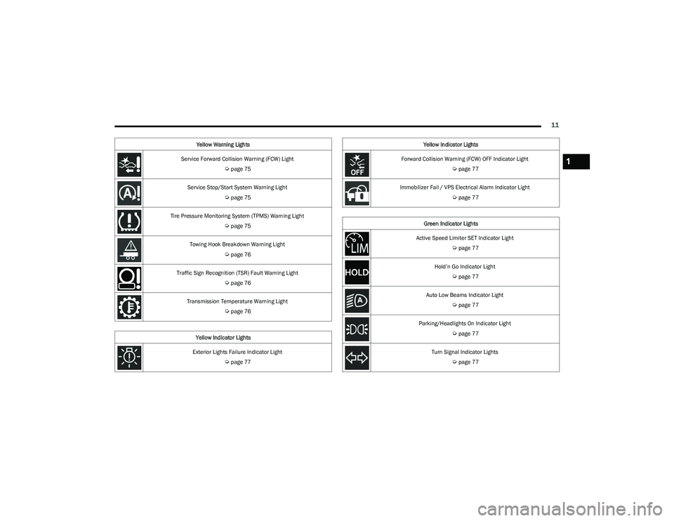
Service Forward Collision Warning (FCW) Light
Úpage 75
Service Stop/Start System Warning Light
Úpage 75
Tire Pressure Monitoring System (TPMS) Warning Light
Úpage 75
Towing Hook Breakdown Warning Light
Úpage 76
Traffic Sign Recognition (TSR) Fault Warning Light
Úpage 76
Transmission Temperature Warning Light
Úpage 76
Yellow Indicator Lights
Exterior Lights Failure Indicator Light
Úpage 77
Yellow Warning Lights
Forward Collision Warning (FCW) OFF Indicator Light
Úpage 77
Immobilizer Fail / VPS Electrical Alarm Indicator Light
Úpage 77
Green Indicator Lights
Active Speed Limiter SET Indicator Light
Úpage 77
Hold’n Go Indicator Light
Úpage 77
Auto Low Beams Indicator Light
Úpage 77
Parking/Headlights On Indicator Light
Úpage 77
Turn Signal Indicator Lights
Úpage 77
Yellow Indicator Lights
1
23_GG_OM_EN_USC_t.book Page 11
Page 28 of 288
26GETTING TO KNOW YOUR VEHICLE
NOTE:
When the Child-Protection Door Lock system is
engaged, the door can be opened only by using the
outside door handle even though the inside door lock
is in the unlocked position.
After disengaging the Child-Protection Door Lock
system, always test the door from the inside to make
certain it is in the desired position.
After engaging the Child-Protection Door Lock system,
always test the door from the inside to make certain it
is in the desired position.
For emergency exit with the system engaged, rotate the
door lock button until the lock indicator is hidden
(unlocked position), lower the window, and open the
door with the outside door handle.
NOTE:Always use this device when carrying children. After
engaging the child lock on both rear doors, check for
effective engagement by trying to open a door with the
internal handle. Once the Child-Protection Door Lock
system is engaged, it is impossible to open the doors from
inside the vehicle. Before getting out of the vehicle, be
sure to check that there is no one left inside.
STEERING WHEEL
TILT/TELESCOPING STEERING COLUMN
This feature allows you to tilt the steering column upward
or downward. It also allows you to lengthen or shorten the
steering column. The tilt/telescoping lever is located
below the steering wheel at the end of the steering
column.
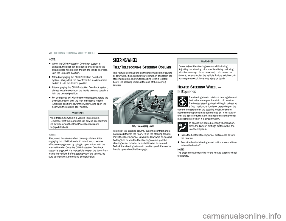
Tilt/Telescoping Lever
To unlock the steering column, push the control handle
downward (toward the floor). To tilt the steering column,
move the steering wheel upward or downward as desired.
To lengthen or shorten the steering column, pull the
steering wheel outward or push it inward as desired.
To lock the steering column in position, push the control
handle upward until fully engaged.
HEATED STEERING WHEEL —
I
F EQUIPPED
The steering wheel contains a heating element
that helps warm your hands in cold weather.
The heated steering wheel will begin to heat at
a fast, medium, or low level depending on the
current temperature of the steering wheel. Once the
heated steering wheel has been turned on, it will stay on
until the operator turns it off. The heated steering wheel
may not turn on when it is already warm.
To access the heated steering wheel button,
press the Comfort settings button within the
Uconnect system.
Press the heated steering wheel button once to turn
the heat on.
Press the heated steering wheel button a second time
to turn the heat off.
NOTE:The engine must be running for the heated steering wheel
to operate.
WARNING!
Avoid trapping anyone in a vehicle in a collision.
Remember that the rear doors can only be opened from
the outside when the Child-Protection locks are
engaged (locked).
WARNING!
Do not adjust the steering column while driving.
Adjusting the steering column while driving or driving
with the steering column unlocked, could cause the
driver to lose control of the vehicle. Failure to follow this
warning may result in serious injury or death.
23_GG_OM_EN_USC_t.book Page 26
Page 34 of 288
32GETTING TO KNOW YOUR VEHICLE
(Continued)
Front Head Restraint Adjustment
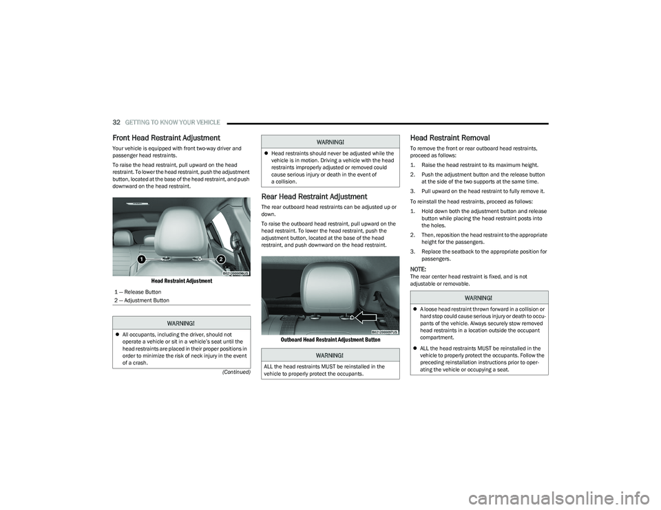
Your vehicle is equipped with front two-way driver and
passenger head restraints.
To raise the head restraint, pull upward on the head
restraint. To lower the head restraint, push the adjustment
button, located at the base of the head restraint, and push
downward on the head restraint.
Head Restraint Adjustment
Rear Head Restraint Adjustment
The rear outboard head restraints can be adjusted up or
down.
To raise the outboard head restraint, pull upward on the
head restraint. To lower the head restraint, push the
adjustment button, located at the base of the head
restraint, and push downward on the head restraint.
Outboard Head Restraint Adjustment Button
Head Restraint Removal
To remove the front or rear outboard head restraints,
proceed as follows:
1. Raise the head restraint to its maximum height.
2. Push the adjustment button and the release button
at the side of the two supports at the same time.
3. Pull upward on the head restraint to fully remove it.
To reinstall the head restraints, proceed as follows:
1. Hold down both the adjustment button and release button while placing the head restraint posts into
the holes.
2. Then, reposition the head restraint to the appropriate height for the passengers.
3. Replace the seatback to the appropriate position for passengers.
NOTE:The rear center head restraint is fixed, and is not
adjustable or removable.
1 — Release Button
2 — Adjustment Button
WARNING!
All occupants, including the driver, should not
operate a vehicle or sit in a vehicle’s seat until the
head restraints are placed in their proper positions in
order to minimize the risk of neck injury in the event
of a crash.
Head restraints should never be adjusted while the
vehicle is in motion. Driving a vehicle with the head
restraints improperly adjusted or removed could
cause serious injury or death in the event of
a collision.
WARNING!
ALL the head restraints MUST be reinstalled in the
vehicle to properly protect the occupants.
WARNING!
WARNING!
A loose head restraint thrown forward in a collision or
hard stop could cause serious injury or death to occu -
pants of the vehicle. Always securely stow removed
head restraints in a location outside the occupant
compartment.
ALL the head restraints MUST be reinstalled in the
vehicle to properly protect the occupants. Follow the
preceding reinstallation instructions prior to oper -
ating the vehicle or occupying a seat.
23_GG_OM_EN_USC_t.book Page 32
Page 36 of 288
34GETTING TO KNOW YOUR VEHICLE
MIRRORS
INSIDE REARVIEW MIRROR
Manual Mirror — If Equipped
The rearview mirror can be adjusted left and right, or tilted
up and down. The mirror should be adjusted to center on
the view through the rear window.
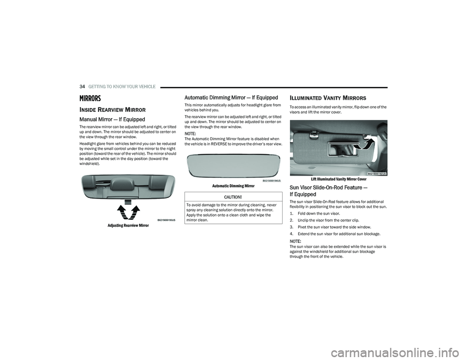
Headlight glare from vehicles behind you can be reduced
by moving the small control under the mirror to the night
position (toward the rear of the vehicle). The mirror should
be adjusted while set in the day position (toward the
windshield).
Adjusting Rearview Mirror
Automatic Dimming Mirror — If Equipped
This mirror automatically adjusts for headlight glare from
vehicles behind you.
The rearview mirror can be adjusted left and right, or tilted
up and down. The mirror should be adjusted to center on
the view through the rear window.
NOTE:The Automatic Dimming Mirror feature is disabled when
the vehicle is in REVERSE to improve the driver’s rear view.
Automatic Dimming Mirror
ILLUMINATED VANITY MIRRORS
To access an illuminated vanity mirror, flip down one of the
visors and lift the mirror cover.
Lift Illuminated Vanity Mirror Cover
Sun Visor Slide-On-Rod Feature —
If Equipped
The sun visor Slide-On-Rod feature allows for additional
flexibility in positioning the sun visor to block out the sun.
1. Fold down the sun visor.
2. Unclip the visor from the center clip.
3. Pivot the sun visor toward the side window.
4. Extend the sun visor for additional sun blockage.
NOTE:The sun visor can also be extended while the sun visor is
against the windshield for additional sun blockage
through the front of the vehicle.
CAUTION!
To avoid damage to the mirror during cleaning, never
spray any cleaning solution directly onto the mirror.
Apply the solution onto a clean cloth and wipe the
mirror clean.
23_GG_OM_EN_USC_t.book Page 34
Page 42 of 288
40GETTING TO KNOW YOUR VEHICLE
EXTERIOR LIGHTS
MULTIFUNCTION LEVER
Multifunction Lever
The multifunction lever controls the operation of the
turn signals, headlight beam selection and passing lights.
The multifunction lever is located on the left side of the
steering column.
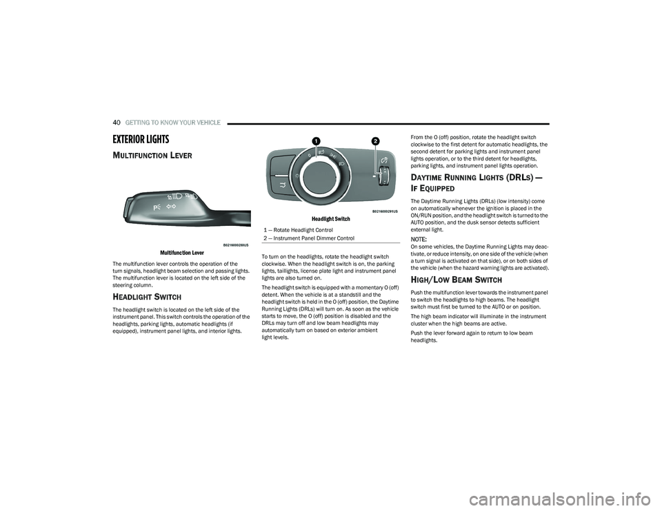
HEADLIGHT SWITCH
The headlight switch is located on the left side of the
instrument panel. This switch controls the operation of the
headlights, parking lights, automatic headlights (if
equipped), instrument panel lights, and interior lights.
Headlight Switch
To turn on the headlights, rotate the headlight switch
clockwise. When the headlight switch is on, the parking
lights, taillights, license plate light and instrument panel
lights are also turned on.
The headlight switch is equipped with a momentary O (off)
detent. When the vehicle is at a standstill and the
headlight switch is held in the O (off) position, the Daytime
Running Lights (DRLs) will turn on. As soon as the vehicle
starts to move, the O (off) position is disabled and the
DRLs may turn off and low beam headlights may
automatically turn on based on exterior ambient
light levels. From the O (off) position, rotate the headlight switch
clockwise to the first detent for automatic headlights, the
second detent for parking lights and instrument panel
lights operation, or to the third detent for headlights,
parking lights, and instrument panel lights operation.
DAYTIME RUNNING LIGHTS (DRLS) —
I
F EQUIPPED
The Daytime Running Lights (DRLs) (low intensity) come
on automatically whenever the ignition is placed in the
ON/RUN position, and the headlight switch is turned to the
AUTO position, and the dusk sensor detects sufficient
external light.
NOTE:On some vehicles, the Daytime Running Lights may deac -
tivate, or reduce intensity, on one side of the vehicle (when
a turn signal is activated on that side), or on both sides of
the vehicle (when the hazard warning lights are activated).
HIGH/LOW BEAM SWITCH
Push the multifunction lever towards the instrument panel
to switch the headlights to high beams. The headlight
switch must first be turned to the AUTO or on position.
The high beam indicator will illuminate in the instrument
cluster when the high beams are active.
Push the lever forward again to return to low beam
headlights.
1 — Rotate Headlight Control
2 — Instrument Panel Dimmer Control
23_GG_OM_EN_USC_t.book Page 40
Page 43 of 288
GETTING TO KNOW YOUR VEHICLE41
AUTOMATIC HIGH BEAM HEADLAMP
C
ONTROL — IF EQUIPPED
The Automatic High Beam Headlamp Control system
provides increased forward lighting at night by automating
high beam control through the use of a digital camera
mounted on the windshield. This camera detects vehicle
specific light and automatically switches from high beams
to low beams until the approaching vehicle is out of view.
NOTE:
The Automatic High Beam Headlamp Control can be
turned on or off through Uconnect Settings.
This function can only be activated with the headlight
switch in the AUTO position.
Broken, muddy, or obstructed headlights and taillights
of vehicles in the field of view will cause headlights to
remain on longer (closer to the vehicle). Also, dirt, film,
and other obstructions on the windshield or camera
lens will cause the system to function improperly.
FLASH-TO-PASS
You can signal another vehicle with your headlights by
lightly pulling the multifunction lever toward you. This will
cause the high beam headlights to turn on, and remain on,
until the lever is released.
AUTOMATIC HEADLIGHTS — IF EQUIPPED
This system automatically turns the headlights
on or off according to ambient light levels. To
turn the system on, rotate the headlight switch
clockwise to the AUTO position.
When the system is on, the headlight time delay feature is
also on. This means the headlights will stay on for up to
90 seconds after you place the ignition into the OFF
position. To turn the automatic system off, move the
headlight switch out of the AUTO position.
NOTE:The engine must be running before the headlights will
come on in the automatic mode.
HEADLIGHTS ON AUTOMATICALLY WITH
W
IPERS — IF EQUIPPED
If your vehicle is equipped with Automatic Headlights, it
also has this customer-programmable feature. When your
headlights are in the automatic mode and the engine is
running, they will automatically turn on when the wiper
system is on. This feature is programmable through the
Uconnect system.
NOTE:When your headlights come on during the daytime, the
vehicle will monitor outside brightness and decide if the
instrument panel needs to be dimmed.
HEADLIGHT DELAY
To aid in your exit, your vehicle is equipped with a
headlight delay that will leave the headlights on for
approximately 90 seconds. This delay is initiated when the
ignition is placed in the OFF position while the headlight
switch is on, and then the headlight switch is cycled off.
Headlight delay can be canceled by either turning the
headlight switch on then off, or by placing the ignition in
the ON/RUN position.
NOTE:The headlight delay time is programmable through
Uconnect Settings Úpage 130.
LIGHTS-ON REMINDER
If the headlights or parking lights are on after the ignition
is in the OFF position, a chime will sound to alert the driver
when the driver's door is opened.
CORNERING LIGHTS — IF EQUIPPED
The cornering lights are a feature to improve visibility at
night while turning the vehicle. When activated, a light
incorporated in the headlight assembly will illuminate on
the side of the vehicle the steering wheel is rotated, or that
the turn signal indicator is on. It can be activated through
the Uconnect system
Úpage 130.
2
23_GG_OM_EN_USC_t.book Page 41
Page 47 of 288
GETTING TO KNOW YOUR VEHICLE45
Windshield Washer
To use the washer, pull the windshield wiper lever toward
the steering wheel and hold.
Both the windshield washer jet and the windshield wipers
will be activated. The wipers and washer will continue to
operate until you let go of the lever.
The windshield wipers stop working three strokes after the
stalk is released, followed by a final stroke six seconds
later to complete the cycle.
Mist
Push the lever upward to the MIST position and release for
a single wiping cycle.
NOTE:The Mist feature does not activate the washer pump;
therefore, no washer fluid will be sprayed on the wind -
shield. The washer function must be used in order to spray
the windshield with washer fluid.
For information on wiper care and replacement, see
Úpage 230.
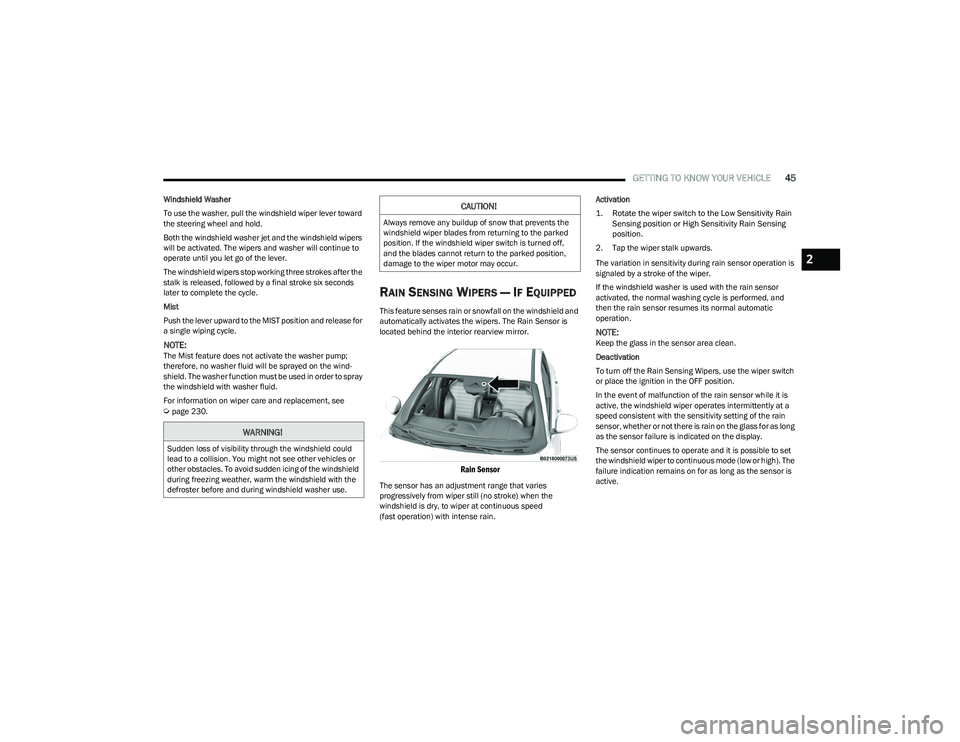
RAIN SENSING WIPERS — IF EQUIPPED
This feature senses rain or snowfall on the windshield and
automatically activates the wipers. The Rain Sensor is
located behind the interior rearview mirror.
Rain Sensor
The sensor has an adjustment range that varies
progressively from wiper still (no stroke) when the
windshield is dry, to wiper at continuous speed
(fast operation) with intense rain. Activation
1. Rotate the wiper switch to the Low Sensitivity Rain
Sensing position or High Sensitivity Rain Sensing
position.
2. Tap the wiper stalk upwards.
The variation in sensitivity during rain sensor operation is
signaled by a stroke of the wiper.
If the windshield washer is used with the rain sensor
activated, the normal washing cycle is performed, and
then the rain sensor resumes its normal automatic
operation.
NOTE:Keep the glass in the sensor area clean.
Deactivation
To turn off the Rain Sensing Wipers, use the wiper switch
or place the ignition in the OFF position.
In the event of malfunction of the rain sensor while it is
active, the windshield wiper operates intermittently at a
speed consistent with the sensitivity setting of the rain
sensor, whether or not there is rain on the glass for as long
as the sensor failure is indicated on the display.
The sensor continues to operate and it is possible to set
the windshield wiper to continuous mode (low or high). The
failure indication remains on for as long as the sensor is
active.
WARNING!
Sudden loss of visibility through the windshield could
lead to a collision. You might not see other vehicles or
other obstacles. To avoid sudden icing of the windshield
during freezing weather, warm the windshield with the
defroster before and during windshield washer use.
CAUTION!
Always remove any buildup of snow that prevents the
windshield wiper blades from returning to the parked
position. If the windshield wiper switch is turned off,
and the blades cannot return to the parked position,
damage to the wiper motor may occur.
2
23_GG_OM_EN_USC_t.book Page 45
Page 48 of 288
46GETTING TO KNOW YOUR VEHICLE
The rain sensor is able to recognize and automatically
adjust itself when the following conditions occur:
Presence of dirt on the controlled surface
(e.g. salt, dirt, etc.).
Presence of streaks of water caused by the worn
window wiper blades.
Difference between day and night.
REAR WINDOW WIPER/WASHER
Shifting the vehicle into REVERSE with the windshield wiper
operating activates a single cycle of the rear window wiper.
Push the windshield wiper lever downward (with the
vehicle in REVERSE) to activate/deactivate continuous
rear wiper operation.
Push the windshield wiper lever downward (without the
vehicle in REVERSE) to activate/deactivate intermittent
rear wiper operation.
Push the windshield wiper lever towards the instrument
panel to activate the rear window washer (a brief push
activates one washing cycle, while keeping the stalk
pushed washes continuously until the stalk is released).
NOTE:Make sure the rear wiper is turned off when cleaning the
windshield glass.
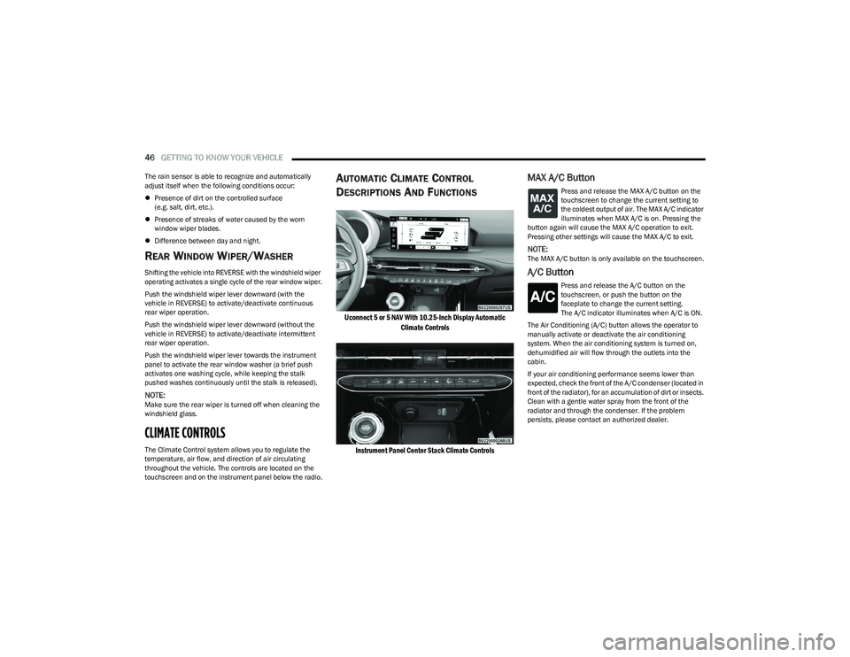
CLIMATE CONTROLS
The Climate Control system allows you to regulate the
temperature, air flow, and direction of air circulating
throughout the vehicle. The controls are located on the
touchscreen and on the instrument panel below the radio.
AUTOMATIC CLIMATE CONTROL
D
ESCRIPTIONS AND FUNCTIONS
Uconnect 5 or 5 NAV With 10.25-Inch Display Automatic
Climate Controls
Instrument Panel Center Stack Climate Controls
MAX A/C Button
Press and release the MAX A/C button on the
touchscreen to change the current setting to
the coldest output of air. The MAX A/C indicator
illuminates when MAX A/C is on. Pressing the
button again will cause the MAX A/C operation to exit.
Pressing other settings will cause the MAX A/C to exit.
NOTE:The MAX A/C button is only available on the touchscreen.
A/C Button
Press and release the A/C button on the
touchscreen, or push the button on the
faceplate to change the current setting.
The A/C indicator illuminates when A/C is ON.
The Air Conditioning (A/C) button allows the operator to
manually activate or deactivate the air conditioning
system. When the air conditioning system is turned on,
dehumidified air will flow through the outlets into the
cabin.
If your air conditioning performance seems lower than
expected, check the front of the A/C condenser (located in
front of the radiator), for an accumulation of dirt or insects.
Clean with a gentle water spray from the front of the
radiator and through the condenser. If the problem
persists, please contact an authorized dealer.
23_GG_OM_EN_USC_t.book Page 46