tow DODGE JOURNEY 2012 1.G Owner's Manual
[x] Cancel search | Manufacturer: DODGE, Model Year: 2012, Model line: JOURNEY, Model: DODGE JOURNEY 2012 1.GPages: 108, PDF Size: 3 MB
Page 73 of 108
- Anti-Lock Brake (ABS) Light
• This light monitors the Anti-Lock Brake System (ABS).
• If the light is not on during starting, stays on, or turns on while driving, werecommend you drive to the nearest service center and have the vehicle serviced
immediately.
- Electronic Throttle Control (ETC) Light
• This light informs you of a problem with the Electronic Throttle Control (ETC)system.
• If a problem is detected, the light will come on while the engine is running. Cycle the ignition when the vehicle has completely stopped and the shift lever is placed
in the PARK position; the light should turn off.
• If the light remains lit with the engine running, your vehicle will usually be drivable; however, see an authorized service center immediately. If the light is
flashing when the engine is running, immediate service is required and you may
experience reduced performance, an elevated/rough idle or engine stall and your
vehicle may require towing.
- Air Bag Warning Light
• If the light is not on during starting, stays on, or turns on while driving, have thevehicle serviced by an authorized service center immediately.
Fuel Cap/Loose Gas Cap Message
• If a “Check Gascap” message appears, tighten the gas cap until a “clicking” soundis heard.
• Press the odometer reset button to turn the message off.
• If the message continues to appear for more than three days after tightening the gas cap, see your authorized service center.
Oil Change Indicator
Message
• If an “oil change due” message appears and a single chime sounds, it is time for your next required oil change.
Resetting The Light After Servicing • Without pressing the brake pedal, push the ENGINE START/STOP button and cycle the ignition to the ON/RUN position (Do not start the engine.)
• Fully depress the accelerator pedal, slowly, three times within 10 seconds.
• Without pressing the brake pedal, push the ENGINE START/STOP button once to return the ignition to the OFF/LOCK position.
WHAT TO DO IN EMERGENCIES
71
Page 75 of 108
JACKING AND TIRE CHANGING
Jack Location
• The jack and jack-handle are stowed underneath a cover in the rear storage bin inthe cargo area.
Spare Tire Location
• The spare tire is stowed underneath the rear of the vehicle and is held in place bymeans of a cable winch mechanism.
Preparations For Jacking
1. Park the vehicle on a firm, level surface as far from the edge of the roadway as possible. Avoid icy or slippery areas.
2. Turn on the Hazard Warning flashers.
3. Set the parking brake.
4. Place the shift lever in PARK.
5. Turn OFF the ignition.
WHAT TO DO IN EMERGENCIES
73
Page 77 of 108
Spare Tire Stowage
NOTE:Refer to “Spare Tire Removal” for
information on assembling the winch tools.
1. Place the spare tire near to the winch cable. Hold the spare upright so that
the tire's tread is on the ground and
the valve stem is at the top of the
wheel facing away from the rear of the
vehicle.
2. Tilt the retainer at the end of the winch cable and drop it through the
center of the wheel. Then place the
spare tire with the cable and retainer
underneath the vehicle.
3. Fit the assembled jack-handle over the winch drive nut. Rotate the jack-handle assembly clockwise to raise the spare tire into the storage area. Continue to rotate
the jack-handle assembly until you hear the winch mechanism click three times.
It cannot be over tightened. Push against the tire several times to be sure it is
held securely in place.
WHAT TO DO IN EMERGENCIES
75
Page 78 of 108
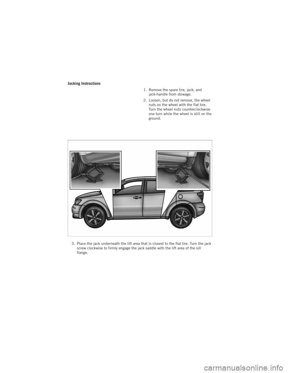
Jacking Instructions
1. Remove the spare tire, jack, andjack-handle from stowage.
2. Loosen, but do not remove, the wheel nuts on the wheel with the flat tire.
Turn the wheel nuts counterclockwise
one turn while the wheel is still on the
ground.
3. Place the jack underneath the lift area that is closest to the flat tire. Turn the jack screw clockwise to firmly engage the jack saddle with the lift area of the sill
flange.
WHAT TO DO IN EMERGENCIES
76
Page 79 of 108
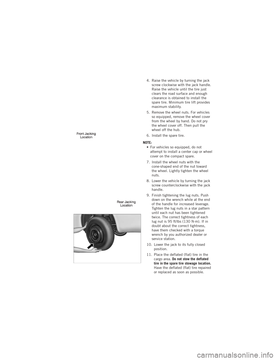
4. Raise the vehicle by turning the jackscrew clockwise with the jack handle.
Raise the vehicle until the tire just
clears the road surface and enough
clearance is obtained to install the
spare tire. Minimum tire lift provides
maximum stability.
5. Remove the wheel nuts. For vehicles so equipped, remove the wheel cover
from the wheel by hand. Do not pry
the wheel cover off. Then pull the
wheel off the hub.
6. Install the spare tire.
NOTE: • For vehicles so equipped, do notattempt to install a center cap or wheel
cover on the compact spare.
7. Install the wheel nuts with the cone-shaped end of the nut toward
the wheel. Lightly tighten the wheel
nuts.
8. Lower the vehicle by turning the jack screw counterclockwise with the jack
handle.
9. Finish tightening the lug nuts. Push down on the wrench while at the end
of the handle for increased leverage.
Tighten the lug nuts in a star pattern
until each nut has been tightened
twice. The correct tightness of each
lug nut is 95 ft/lbs (130 N·m). If in
doubt about the correct tightness,
have them checked with a torque
wrench by you authorized dealer or
service station.
10. Lower the jack to its fully closed position.
11. Place the deflated (flat) tire in the cargo area. Do not stow the deflated
tire in the spare tire stowage location.
Have the deflated (flat) tire repaired
or replaced as soon as possible.
WHAT TO DO IN EMERGENCIES
77
Page 80 of 108
12. To stow the winch cable and retainer, fit the assembled jack-handle over thewinch drive nut. Rotate the jack-handle assembly clockwise until you hear the
winch mechanism click three times. It cannot be over tightened.
13. Stow the jack-handle and jack.
14. Check the tire pressure as soon as possible. Adjust the tire pressure as required.
Road Tire Installation
Vehicles Equipped With Wheel Covers
1. Mount the road tire on the axle.
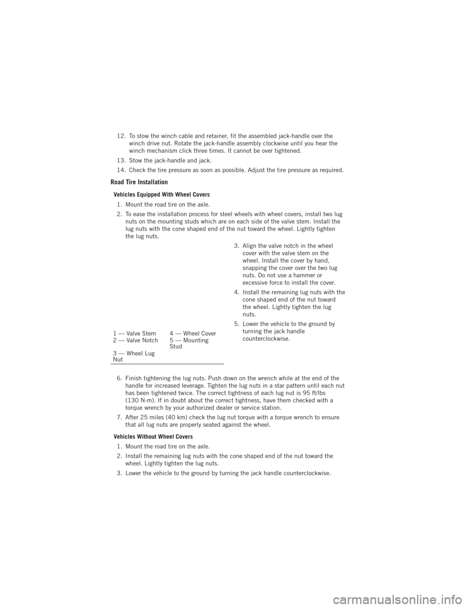
2. To ease the installation process for steel wheels with wheel covers, install two lug nuts on the mounting studs which are on each side of the valve stem. Install the
lug nuts with the cone shaped end of the nut toward the wheel. Lightly tighten
the lug nuts.
3. Align the valve notch in the wheelcover with the valve stem on the
wheel. Install the cover by hand,
snapping the cover over the two lug
nuts. Do not use a hammer or
excessive force to install the cover.
4. Install the remaining lug nuts with the cone shaped end of the nut toward
the wheel. Lightly tighten the lug
nuts.
5. Lower the vehicle to the ground by turning the jack handle
counterclockwise.
6. Finish tightening the lug nuts. Push down on the wrench while at the end of the handle for increased leverage. Tighten the lug nuts in a star pattern until each nut
has been tightened twice. The correct tightness of each lug nut is 95 ft/lbs
(130 N·m). If in doubt about the correct tightness, have them checked with a
torque wrench by your authorized dealer or service station.
7. After 25 miles (40 km) check the lug nut torque with a torque wrench to ensure that all lug nuts are properly seated against the wheel.
Vehicles Without Wheel Covers 1. Mount the road tire on the axle.
2. Install the remaining lug nuts with the cone shaped end of the nut toward the wheel. Lightly tighten the lug nuts.
3. Lower the vehicle to the ground by turning the jack handle counterclockwise.
1 — Valve Stem 4 — Wheel Cover
2 — Valve Notch 5 — Mounting Stud
3 — Wheel Lug
Nut
WHAT TO DO IN EMERGENCIES
78
Page 82 of 108
WARNING!(Continued)
• To assure that spare tires, flat or inflated, are securely stowed, spares mustbe stowed with the valve stem facing the ground.
• Raising the vehicle higher than necessary can make the vehicle less stable. It could slip off the jack and hurt someone near it. Raise the vehicle only
enough to remove the tire.
• To avoid possible personal injury, handle the wheel covers with care to avoid contact with any sharp edges.
• To avoid the risk of forcing the vehicle off the jack, do not tighten the wheel nuts fully until the vehicle has been lowered. Failure to follow this warning
may result in personal injury.
• A loose tire or jack, thrown forward in a collision or hard stop could endanger the occupants of the vehicle. Always stow the jack parts and the spare tire in
the places provided. Have the deflated (flat) tire repaired or replaced
immediately.
JUMP-STARTING
• If your vehicle has a discharged batteryit can be jump-started using a set of
jumper cables and a battery in another
vehicle or by using a portable battery
booster pack.
• Jump-starting can be dangerous if done improperly so please follow the
procedures in this section carefully.
NOTE: When using a portable battery
booster pack follow the manufacturer's
operating instructions and precautions.
Preparations for Jump-Start
• The battery in your vehicle is located between the left front headlight assembly and the left front wheel splash shield. To allow jump-starting there are remote
battery posts located on the left side of the engine compartment.
• Set the parking brake, shift the automatic transmission into PARK and turn the ignition to LOCK.
• Turn off the heater, radio, and all unnecessary electrical accessories.
• Remove the protective cover over the remote positive (+)battery post. To remove
the cover, press the locking tab and pull upward on the cover.
• If using another vehicle to jump-start the battery, park the vehicle within the jumper cables reach, set the parking brake and make sure the ignition is OFF.
WHAT TO DO IN EMERGENCIES
80
Page 85 of 108
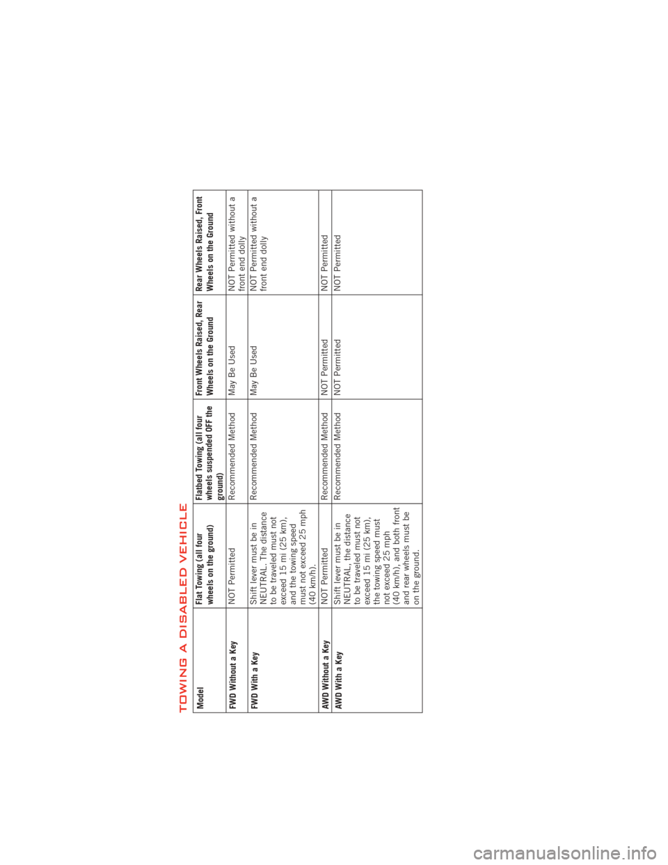
TOWING A DISABLED VEHICLEModelFlat Towing (all four
wheels on the ground)Flatbed Towing (all four
wheels suspended OFF the
ground)Front Wheels Raised, Rear
Wheels on the Ground
Rear Wheels Raised, Front
Wheels on the Ground
FWD Without a Key NOT Permitted
Recommended Method May Be Used NOT Permitted without a
front end dolly
FWD With a Key Shift lever must be in
NEUTRAL. The distance
to be traveled must not
exceed 15 mi (25 km),
and the towing speed
must not exceed 25 mph
(40 km/h).Recommended Method May Be Used
NOT Permitted without a
front end dolly
AWD Without a Key NOT Permitted
Recommended Method NOT Permitted NOT Permitted
AWDWithaKey Shift lever must be in
NEUTRAL, the distance
to be traveled must not
exceed 15 mi (25 km),
the towing speed must
not exceed 25 mph
(40 km/h), and both front
and rear wheels must be
on the ground.Recommended Method NOT Permitted
NOT Permitted
WHAT TO DO IN EMERGENCIES
83
Page 93 of 108
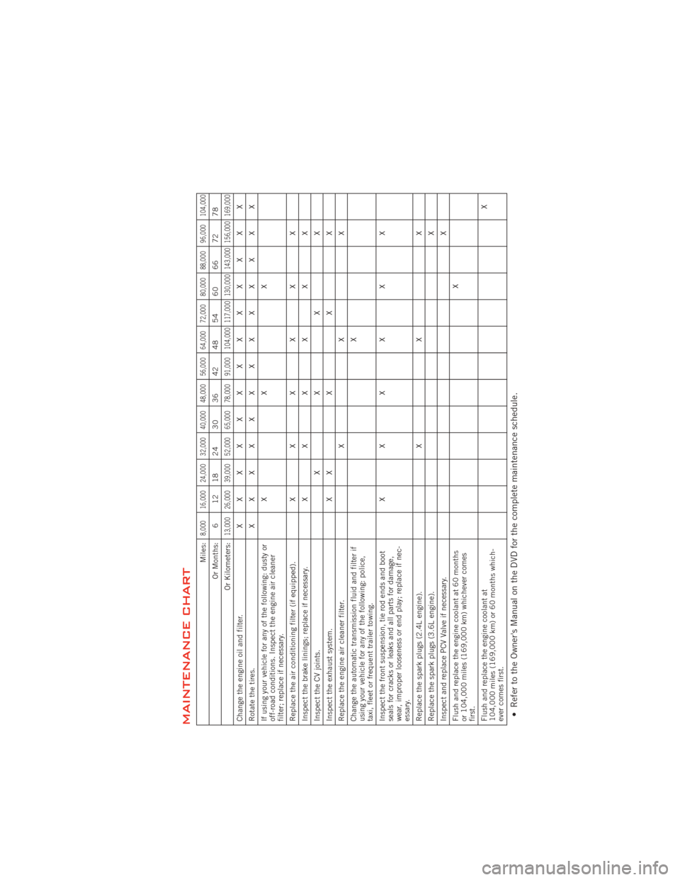
MAINTENANCE CHART
Miles:
8,000 16,000 24,000 32,000 40,000 48,000 56,000 64,000 72,000 80,000 88,000 96,000 104,000
Or Months: 6 12 18 24 30 36 42 48 54 60 66 72 78
Or Kilometers:
13,000 26,000 39,000 52,000 65,000 78,000 91,000 104,000 117,000 130,000 143,000 156,000 169,000
Change the engine oil and filter. XXXXXXXXXXXXX
Rotate the tires. XXXXXXXXXXXXX
If using your vehicle for any of the following: dusty or
off-road conditions. Inspect the engine air cleaner
filter; replace if necessary. XXX
Replace the air conditioning filter (if equipped). XXXXXX
Inspect the brake linings; replace if necessary. XXXXXX
Inspect the CV joints. XXXX
Inspect the exhaust system. XXXXX
Replace the engine air cleaner filter. XXX
Change the automatic transmission fluid and filter if
using your vehicle for any of the following: police,
taxi, fleet or frequent trailer towing. X
Inspect the front suspension, tie rod ends and boot
seals for cracks or leaks and all parts for damage,
wear, improper looseness or end play; replace if nec-
essary. XXXXXX
Replace the spark plugs (2.4L engine). XXX
Replace the spark plugs (3.6L engine). X
Inspect and replace PCV Valve if necessary. X
Flush and replace the engine coolant at 60 months
or 104,000 miles (169,000 km) whichever comes
first. X
Flush and replace the engine coolant at
104,000 miles (169,000 km) or 60 months which-
ever comes first. X• Refer to the Owner's Manual on the DVD for the complete maintenance schedule.
MAINTAINING YOUR VEHICLE
91
Page 95 of 108
FUSES
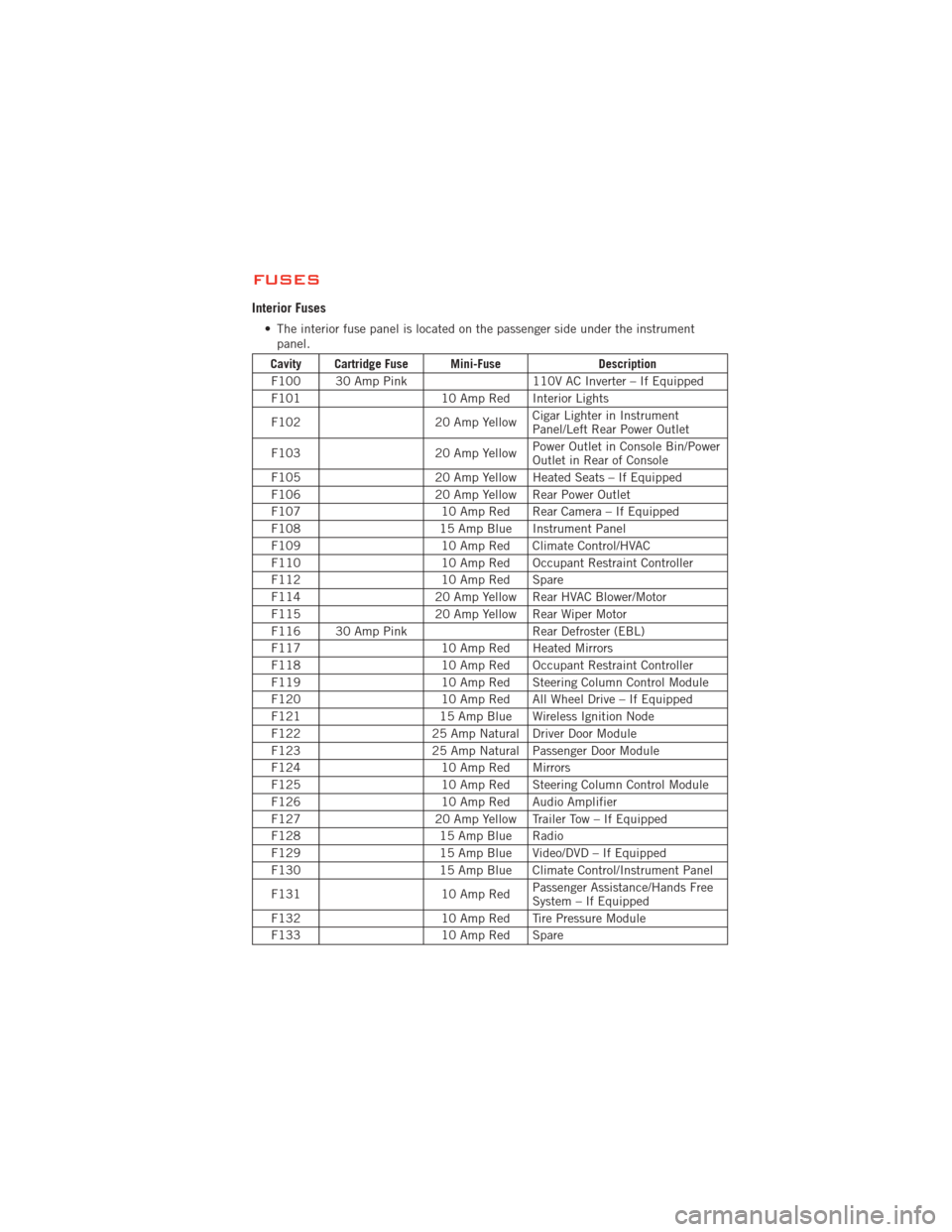
Interior Fuses
• The interior fuse panel is located on the passenger side under the instrumentpanel.
Cavity Cartridge Fuse Mini-Fuse Description
F100 30 Amp Pink 110V AC Inverter – If Equipped
F101 10 Amp Red Interior Lights
F102 20 Amp YellowCigar Lighter in Instrument
Panel/Left Rear Power Outlet
F103 20 Amp YellowPower Outlet in Console Bin/Power
Outlet in Rear of Console
F105 20 Amp Yellow Heated Seats – If Equipped
F106 20 Amp Yellow Rear Power Outlet
F107 10 Amp Red Rear Camera – If Equipped
F108 15 Amp Blue Instrument Panel
F109 10 Amp Red Climate Control/HVAC
F110 10 Amp Red Occupant Restraint Controller
F112 10 Amp Red Spare
F114 20 Amp Yellow Rear HVAC Blower/Motor
F115 20 Amp Yellow Rear Wiper Motor
F116 30 Amp Pink Rear Defroster (EBL)
F117 10 Amp Red Heated Mirrors
F118 10 Amp Red Occupant Restraint Controller
F119 10 Amp Red Steering Column Control Module
F120 10 Amp Red All Wheel Drive – If Equipped
F121 15 Amp Blue Wireless Ignition Node
F122 25 Amp Natural Driver Door Module
F123 25 Amp Natural Passenger Door Module
F124 10 Amp Red Mirrors
F125 10 Amp Red Steering Column Control Module
F126 10 Amp Red Audio Amplifier
F127 20 Amp Yellow Trailer Tow – If Equipped
F128 15 Amp Blue Radio
F129 15 Amp Blue Video/DVD – If Equipped
F130 15 Amp Blue Climate Control/Instrument Panel
F131 10 Amp RedPassenger Assistance/Hands Free
System – If Equipped
F132 10 Amp Red Tire Pressure Module
F133 10 Amp Red Spare
MAINTAINING YOUR VEHICLE
93