instrument panel DODGE JOURNEY 2012 1.G User Guide
[x] Cancel search | Manufacturer: DODGE, Model Year: 2012, Model line: JOURNEY, Model: DODGE JOURNEY 2012 1.GPages: 108, PDF Size: 3 MB
Page 7 of 108

A. Headlight Switch pg. 26
B. Turn Signal/Wiper/Washer/High BeamsLever pg. 25
C. Electronic Vehicle Information Center (EVIC) Controls pg. 60
D. Instrument Cluster pg. 6
E. Electronic Vehicle Information Center (EVIC) Display pg. 60
F. Engine Start/Stop Button (behind steering wheel) pg. 10
G. Uconnect Touch™ System pg. 34 H. SWITCH PANEL
− Hazard Switch
− A/C pg. 28
− Recirculation pg. 28
− Front Defrost pg. 28
− Rear Defrost pg. 28
− Electronic Stability Control (ESC) Offpg. 68 I. Climate Control Hard Knobs pg. 28
J. Power Outlet pg. 65
K. Transmission Shift Lever
L. Speed Control pg. 27
M. Power Mirrors
N. Power Windows
O. Power Door Locks
CONTROLS AT A GLANCE
5
Page 15 of 108
WARNING!
In a collision, you and your passengers can suffer much greater injuries if you
are not buckled up properly. You can strike the interior of your vehicle or other
passengers, or you can be thrown out of the vehicle. Always be sure you and
others in your vehicle are buckled up properly.
SUPPLEMENTAL RESTRAINT SYSTEM (SRS) —
AIR BAGS
• This vehicle has Advanced Front Air Bags for both the driver and right frontpassenger as a supplement to the seat belt restraint system. The Advanced Front
Air Bags will not deploy in every type of collision.
• Advanced Front Air Bags are designed to provide additional protection by supplementing the seat belts in certain frontal collisions depending on the severity
and type of collision. Advanced Front Air Bags are not expected to reduce the risk
of injury in rear, side, or rollover collisions.
• This vehicle is equipped with Supplemental Side Air Bag Inflatable Curtains to protect the driver, front and rear passengers sitting next to a window.
• This vehicle is equipped with Supplemental Seat-Mounted Side Air Bags to provide enhanced protection to help protect an occupant during a side impact.
• This vehicle is equipped with a Supplemental Driver Side Knee Air Bag to provide enhanced protection and work together with the Driver Advanced Front Air Bag
during a frontal impact.
• If the Air Bag Warning Light
is not on during starting, stays on, or turns on
while driving, have the vehicle serviced by an authorized service center
immediately.
• Refer to the Owner's Manual on the DVD for further details regarding the Supplemental Restraint System (SRS).
WARNING!
• Relying on the air bags alone could lead to more severe injuries in a collision.The air bags work with your seat belt to restrain you properly. In some
collisions, the air bags won't deploy at all. Always wear your seat belts even
though you have air bags.
• Being too close to the steering wheel or instrument panel during Advanced Front Air Bag deployment could cause serious injury, including death. Air
bags need room to inflate. Sit back, comfortably extending your arms to
reach the steering wheel or instrument panel.
• Supplemental Side Air Bag Inflatable Curtains and Supplemental Seat-Mounted Side Air Bags need room to inflate. Do not lean against the
door or window. Sit upright in the center of the seat.
(Continued)
GETTING STARTED
13
Page 28 of 108
Front Wipers
Intermittent, Low And High Operation• Rotate the end of the lever to the first detent position for one of five intermittent settings, the second detent for low wiper operation and the third detent for high
wiper operation.
Washer Operation
• Push the end of the lever in to the second detent and release.
Mist
• Push the end of the lever in to the first detent and release.
NOTE: The mist feature does not activate the washer pump; therefore, no washer fluid
will be sprayed on the windshield. The wash function must be activated in order to
spray the windshield with washer fluid.
Rear Wiper
Wiper Operation
• Rotate the center portion of the lever forward to the first detent for rear wiper operation.
Washer Operation
• Rotate the center portion of the lever past the first detent to activate the rear washer.
HEADLIGHT SWITCH
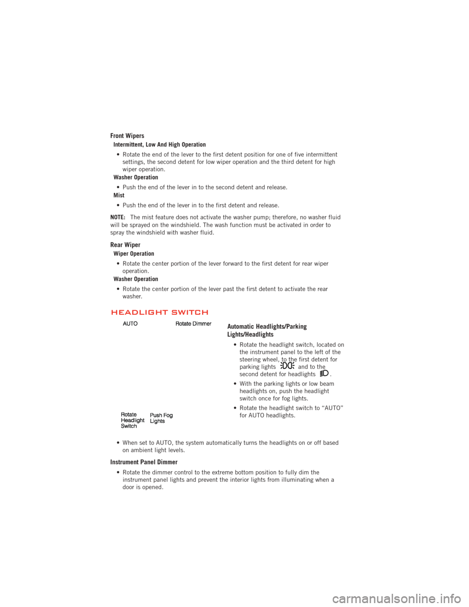
Automatic Headlights/Parking
Lights/Headlights
• Rotate the headlight switch, located onthe instrument panel to the left of the
steering wheel, to the first detent for
parking lights
andtothe
second detent for headlights.
• With the parking lights or low beam headlights on, push the headlight
switch once for fog lights.
• Rotate the headlight switch to “AUTO” for AUTO headlights.
• When set to AUTO, the system automatically turns the headlights on or off based on ambient light levels.
Instrument Panel Dimmer
• Rotate the dimmer control to the extreme bottom position to fully dim theinstrument panel lights and prevent the interior lights from illuminating when a
door is opened.
OPERATING YOUR VEHICLE
26
Page 29 of 108
• Rotate the dimmer control up to increase the brightness of the instrument panelwhen the parking lights or headlights are on.
• Rotate the dimmer control up to the next detent position to fully brighten the odometer and radio when the parking lights or headlights are on. Refer to your
Media Center/Radio User Manual on the DVD for display dimming.
• Rotate the dimmer control up to the last detent position to turn on the interior lighting.
SPEED CONTROL
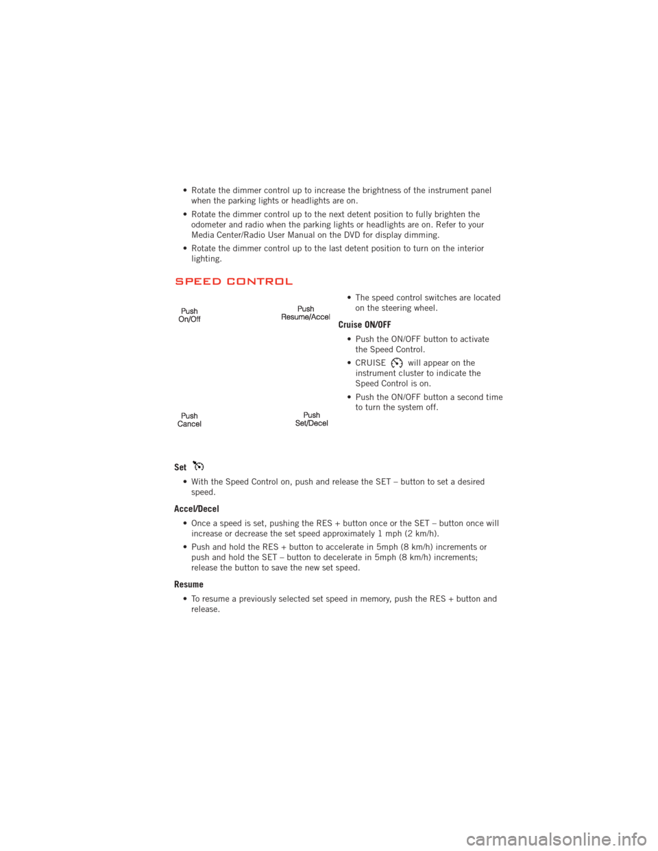
• The speed control switches are locatedon the steering wheel.
Cruise ON/OFF
• Push the ON/OFF button to activatethe Speed Control.
• CRUISE
will appear on the
instrument cluster to indicate the
Speed Control is on.
• Push the ON/OFF button a second time to turn the system off.
Set
• With the Speed Control on, push and release the SET – button to set a desiredspeed.
Accel/Decel
• Once a speed is set, pushing the RES + button once or the SET – button once willincrease or decrease the set speed approximately 1 mph (2 km/h).
• Push and hold the RES + button to accelerate in 5mph (8 km/h) increments or push and hold the SET – button to decelerate in 5mph (8 km/h) increments;
release the button to save the new set speed.
Resume
• To resume a previously selected set speed in memory, push the RES + button andrelease.
OPERATING YOUR VEHICLE
27
Page 33 of 108
PARKVIEW®REAR BACK-UP CAMERA
• You can see an on-screen image of the rear of your vehicle whenever the shift leveris put into REVERSE. The ParkView®Rear Back-Up Camera image will be
displayed on the radio display screen, located on the center stack of the
instrument panel.
• If the radio display screen appears foggy, clean the camera lens located on the liftgate.
WARNING!
Drivers must be careful when backing up even when using the ParkView®Rear
Back-Up Camera. Always check carefully behind your vehicle, and be sure to
check for pedestrians, animals, other vehicles, obstructions, or blind spots
before backing up. You must continue to pay attention while backing up.
Failure to do so can result in serious injury or death.
POWER SUNROOF
Manual Open/Close
• Press and hold the switch rearward to open or forward to close the sunroof. Any release of the switch will stop the movement, and the sunroof will remain in a
partially open or closed position until the switch is pressed again.
Pinch Protection Feature
• This feature will detect an obstruction in the opening of the sunroof or the shadeduring Express Close operation. If an obstruction in the path of the sunroof or
shade is detected, the sunroof or shade will automatically return to the open
position.
NOTE: Pinch protection is disabled while the switch is pressed and held during manual
opening and closing of the sunroof or shade.
OPERATING YOUR VEHICLE
31
Page 88 of 108
OPENING THE HOOD
• Pull the hood release lever locatedunder the left side of the instrument
panel.
• Raise the hood and locate the safety latch, in the middle of the hood
opening.
• Move the safety latch while lifting the hood at the same time.
• Insert the support rod into the slot on the hood.
• To close the hood, remove the support rod and place it in the retaining clip,
then lower the hood slowly.
WARNING!
Be sure the hood is fully latched before driving your vehicle. If the hood is not
fully latched, it could open when the vehicle is in motion and block your vision.
Failure to follow this warning could result in serious injury or death.
MAINTAINING YOUR VEHICLE
86
Page 95 of 108
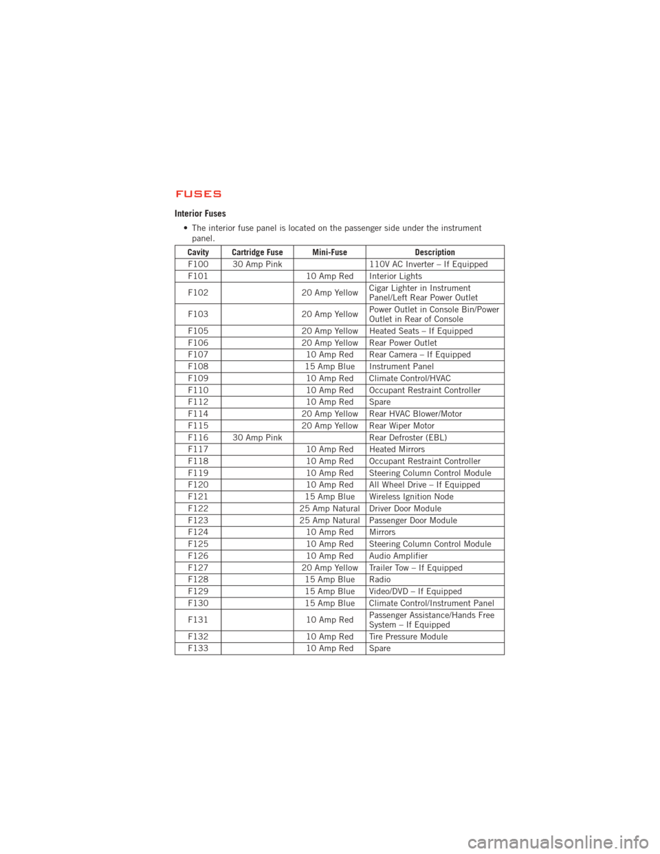
FUSES
Interior Fuses
• The interior fuse panel is located on the passenger side under the instrumentpanel.
Cavity Cartridge Fuse Mini-Fuse Description
F100 30 Amp Pink 110V AC Inverter – If Equipped
F101 10 Amp Red Interior Lights
F102 20 Amp YellowCigar Lighter in Instrument
Panel/Left Rear Power Outlet
F103 20 Amp YellowPower Outlet in Console Bin/Power
Outlet in Rear of Console
F105 20 Amp Yellow Heated Seats – If Equipped
F106 20 Amp Yellow Rear Power Outlet
F107 10 Amp Red Rear Camera – If Equipped
F108 15 Amp Blue Instrument Panel
F109 10 Amp Red Climate Control/HVAC
F110 10 Amp Red Occupant Restraint Controller
F112 10 Amp Red Spare
F114 20 Amp Yellow Rear HVAC Blower/Motor
F115 20 Amp Yellow Rear Wiper Motor
F116 30 Amp Pink Rear Defroster (EBL)
F117 10 Amp Red Heated Mirrors
F118 10 Amp Red Occupant Restraint Controller
F119 10 Amp Red Steering Column Control Module
F120 10 Amp Red All Wheel Drive – If Equipped
F121 15 Amp Blue Wireless Ignition Node
F122 25 Amp Natural Driver Door Module
F123 25 Amp Natural Passenger Door Module
F124 10 Amp Red Mirrors
F125 10 Amp Red Steering Column Control Module
F126 10 Amp Red Audio Amplifier
F127 20 Amp Yellow Trailer Tow – If Equipped
F128 15 Amp Blue Radio
F129 15 Amp Blue Video/DVD – If Equipped
F130 15 Amp Blue Climate Control/Instrument Panel
F131 10 Amp RedPassenger Assistance/Hands Free
System – If Equipped
F132 10 Amp Red Tire Pressure Module
F133 10 Amp Red Spare
MAINTAINING YOUR VEHICLE
93