Seat DODGE JOURNEY 2013 1.G Owner's Manual
[x] Cancel search | Manufacturer: DODGE, Model Year: 2013, Model line: JOURNEY, Model: DODGE JOURNEY 2013 1.GPages: 116, PDF Size: 3.43 MB
Page 23 of 116
Recliner Adjustment
• The seatback release lever is on the outboard side of the seat. To recline the seat, leanback, lift the lever, position the seatback as desired, and then release the lever. To return
the seatback to its normal upright position, lean back, lift the lever, lean forward, and then
release the lever once the seatback is in the upright position.
STADIUM Tip ’n Slide™ (EASY ENTRY/EXIT SEAT) — SEVEN PASSENGER MODELS
To Move The Second-Row Passenger Seat Forward
NOTE:
Raise the 20% seatback/armrest before moving the 60% seat to allow for full seat travel.
• To allow passengers to easily enter or exit the third-row passenger seats move the Tip ’n Slide™ control lever on the upper outboard side of the seatback forward, and in one fluid
motion, the seat cushion flips upward and the seat moves forward on its tracks.
To Unfold And Move The Second-Row
Passenger Seat Rearward
• Move the seatback rearward until it locks in place and then continue sliding the
seat rearward on its tracks until it locks in
place.
• Push the seat cushion downward to lock it in place.
• Adjust the seat track position as desired.
50/50 SPLIT THIRD-ROW PASSENGER SEATS WITH FOLD-FLAT FEATURE
To Fold The Seat
• With the second-row passenger seat fully upright, pull the latch release-loop located at the top of the seatback upward, push the seat forward slightly, and release the release-
loop. Then, continue to push the seat forward. The head restraints will fold automatically
as the seat moves forward.
To Unfold The Seat
• Grasp the assist strap loop on the seatback and pull it toward you to raise the seatback.Continue to raise the seatback until it locks in place. Then, raise the head restraint to lock
it in place.
• To lock the seatback in a reclined position, pull the latch release-loop located at the top of the seatback upward, allow the seatback to recline, then release the release-loop.
GETTING STARTED
21
Page 24 of 116
WARNING!
• Be certain that the seatback is locked securely into position. Otherwise, the seat willnot provide the proper stability for child seats and/or passengers. An improperly
latched seat could cause you and others to be severely injured or killed.
• Do not allow a passenger to sit in a third row seat without having the head restraint
unfolded and locked in place or seatback(s) folded flat. Failure to follow this warning
may result in the passengers being severely injured or killed in the event of a collision.
• Do not drive the vehicle with the seat in the Tip 'n Slide™ position, as it is only intended for entering and exiting the third row seats. Failure to follow this warning may result
in you and others being severely injured or killed.
• Be certain that the seatback and seat are locked securely into position. Otherwise,
the seat will not provide the proper stability for child seats and/or passengers. An
improperly latched seat could cause you or others to be severely injured or killed.
HEATED SEATS
Front Heated Seats
• The heated seats are operated using the Uconnect® System.
Uconnect® 4.3
• Press the Climate hard-key (located onthe left side of the Uconnect® screen) to
enter the climate control screen.
• Press the Driver or Passenger seat soft- key once to select HI-level heating. Press
the soft-key a second time to select LO-
level heating. Press the soft-key a third
time to shut the heating elements OFF.
• If the High-level setting is selected, the system will automatically switch to Low-
level after approximately 60 minutes. The
Low-level setting will turn Off automati-
cally after approximately 45 minutes.
GETTING STARTED
22
Page 25 of 116
Uconnect® 8.4
• Press the Controls soft-key located on theUconnect® screen.
• Press the Driver or Passenger seat soft- key once to select HI-level heating. Press
the soft-key a second time to select LO-
level heating. Press the soft-key a third
time to shut the heating elements OFF.
• If the High-level setting is selected, the system will automatically switch to Low-
level after approximately 60 minutes. The
Low-level setting will turn Off automati-
cally after approximately 45 minutes.
WARNING!
• Persons who are unable to feel pain to the skin because of advanced age, chronic
illness, diabetes, spinal cord injury, medication, alcohol use, exhaustion or other
physical conditions must exercise care when using the seat heater. It may cause
burns even at low temperatures, especially if used for long periods of time.
• Do not place anything on the seat that insulates against heat, such as a blanket or
cushion. This may cause the seat heater to overheat. Sitting in a seat that has been
overheated could cause serious burns due to the increased surface temperature of
the seat.
HEATED STEERING WHEEL
• The steering wheel contains a heating element that heats the steering wheel to onetemperature setting.
• To access the Heated Steering Wheel soft-key, touch the Controls soft-key located on the Uconnect® display.
• Touch the soft-key once to turn the heating element On. Press the soft-key a second time to turn the heating element Off.
• Once the heated steering wheel has been turned on, it will operate for approximately 58 to 70 minutes before automatically shutting off. The heated steering wheel can shut
off early or may not turn on when the steering wheel is already warm.
GETTING STARTED
23
Page 35 of 116
Pinch Protection Feature
• This feature will detect an obstruction in the opening of the sunroof during Express Closeoperation. If an obstruction in the path of the sunroof is detected, the sunroof will
automatically retract. Remove the obstruction if this occurs. Next, press the switch
forward and release to Express Close.
NOTE:
If three consecutive sunroof close attempts result in Pinch Protect reversals, the fourth
close attempt will be a Manual Close movement with Pinch Protect disabled.
WARNING!
• Never leave children unattended in a vehicle, and do not leave the key in the ignition switch (or leave the ignition of a vehicle equipped with Keyless Enter-N-Go™ in the
ACC or ON/Run position). Occupants, particularly unattended children, can become
entrapped by the power sunroof while operating the power sunroof switch. Such
entrapment may result in serious injury or death.
• In a collision, there is a greater risk of being thrown from a vehicle with an open
sunroof. You could also be severely injured or killed. Always fasten your seat belt
properly and make sure all passengers are properly secured.
• Do not allow small children to operate the sunroof. Never allow your fingers, other
body parts, or any object to project through the sunroof opening. Injury may result.
WIND BUFFETING
• Wind buffeting can be described as a helicopter-type percussion sound. If buffetingoccurs with the rear windows open, adjust the front and rear windows together.
• If buffeting occurs with the sunroof open, adjust the sunroof opening, or adjust any window. This will minimize buffeting.
OPERATING YOUR VEHICLE
33
Page 61 of 116
WARNING!
Any voice commanded system should be used only in safe driving conditions following
applicable laws regarding phone use. Your attention should be focused on safely oper-
ating the vehicle. Failure to do so may result in a collision causing you and others to be
severely injured or killed.
VIDEO ENTERTAINMENT SYSTEM (VES™)
System Operation
• The screen is located on the headliner behind the front seat. To lower the screen, pressthe release button located in the rear of the overhead console.
• The system may be controlled by the front seat occupants using the touch-screen radio, or by the rear seat occupants using the remote control.
• The video screen displays information in a split-screen format. The left side of the screen is referred to as Channel 1 and the right side of the screen is referred to as Channel 2.
All modes except video modes are displayed in a split-screen format.
• To use the headphones, press the power button located on the right ear cup. Select the channel on the headphones (1 or 2) that corresponds to the channel selected on the
VES™ screen.
Operation Of The Remote
•
The remote control operates similarly to any DVD remote you have used before and allows
the rear seat passengers to change stations, tracks, discs and audio/video modes.
• The remote control is designed to control either channel by using the selector switch located on the right side of the remote.
• Pressing the power button will turn the VES™ system ON/OFF.
• Pressing the MODE button causes the Mode Selection menu to appear on the VES™ screen. Use the remote control arrow buttons to scroll through the available modes, then
press ENTER to select the desired mode.
Auxiliary Audio/Video Input Jacks
• The Aux jacks are located on the rear of the center console.
• Connect the video game or other external media devices to the AUX jacks following the color coding for VES™ jacks.
• Using either the touch-screen radio or remote control, select AUX from the Rear VES™ Control or Mode Selection screen.
• Refer to your vehicle's Owners Manual on the DVD for further details.
ELECTRONICS
59
Page 63 of 116
Uconnect® 4.3 Customer Programmable Features
• The Uconnect® 4.3 system allows you to access Customer Programmable feature set-tings such as Display, Clock, Safety/Assistance, Lights, Doors & Locks, Heated Seats,
Engine Off Operation, Compass Settings, Audio, Phone/ Bluetooth and SIRIUS Setup
through hard-keys and soft-keys.
• Press the Settings hard-key to on the right side of the unit to access the Settings screen, use the Page Up/Down soft-keys to scroll through the following settings. The following
feature settings are available:
• Display • Engine Off Options
• Clock • Compass Settings
• Safety / Assistance • Audio
• Lights • Phone / Bluetooth
• Doors & Locks • SIRIUS Setup
• Heated Seats
Uconnect® 8.4 Customer Programmable Features
• The Uconnect® 8.4 system allows you to access Customer Programmable feature set- tings such as Display, Clock, Safety/Assistance, Lights, Doors & Locks, Heated Seats,
Engine Off Operation, Compass Settings, Audio, Phone/ Bluetooth and SIRIUS Setup
through soft-keys.
• Touch the More soft-key on the bottom of the screen, then touch the Settings soft-key to access the Settings screen. When making a selection, scroll up or down until the
preferred setting is highlighted, then press and release the preferred setting until a
check-mark appears next to the setting, showing that setting has been selected. The
following feature settings are available:
• Display • Engine Off Options
• Clock • Compass Settings
• Safety / Assistance • Audio
• Lights • Phone / Bluetooth
• Doors & Locks • SIRIUS Setup
• Heated Seats
ELECTRONICS
61
Page 76 of 116
Preparations For Jacking
1. Park the vehicle on a firm, level surface as far from the edge of the roadway as possible.Avoid icy or slippery areas.
2. Turn on the Hazard Warning flashers.
3. Set the parking brake.
4. Place the shift lever in PARK.
5. Turn OFF the ignition.
6. Block both the front and rear of the wheel diagonally opposite of the jacking position. For example, if changing the right front tire, block the left rear wheel.
NOTE:
Passengers should not remain in the vehicle
when the vehicle is being jacked.
Spare Tire Removal
NOTE:
On seven-passenger models, fold the third-row passenger seats flat. This will provide more
space when accessing the jacking tools and when operating the winch mechanism.
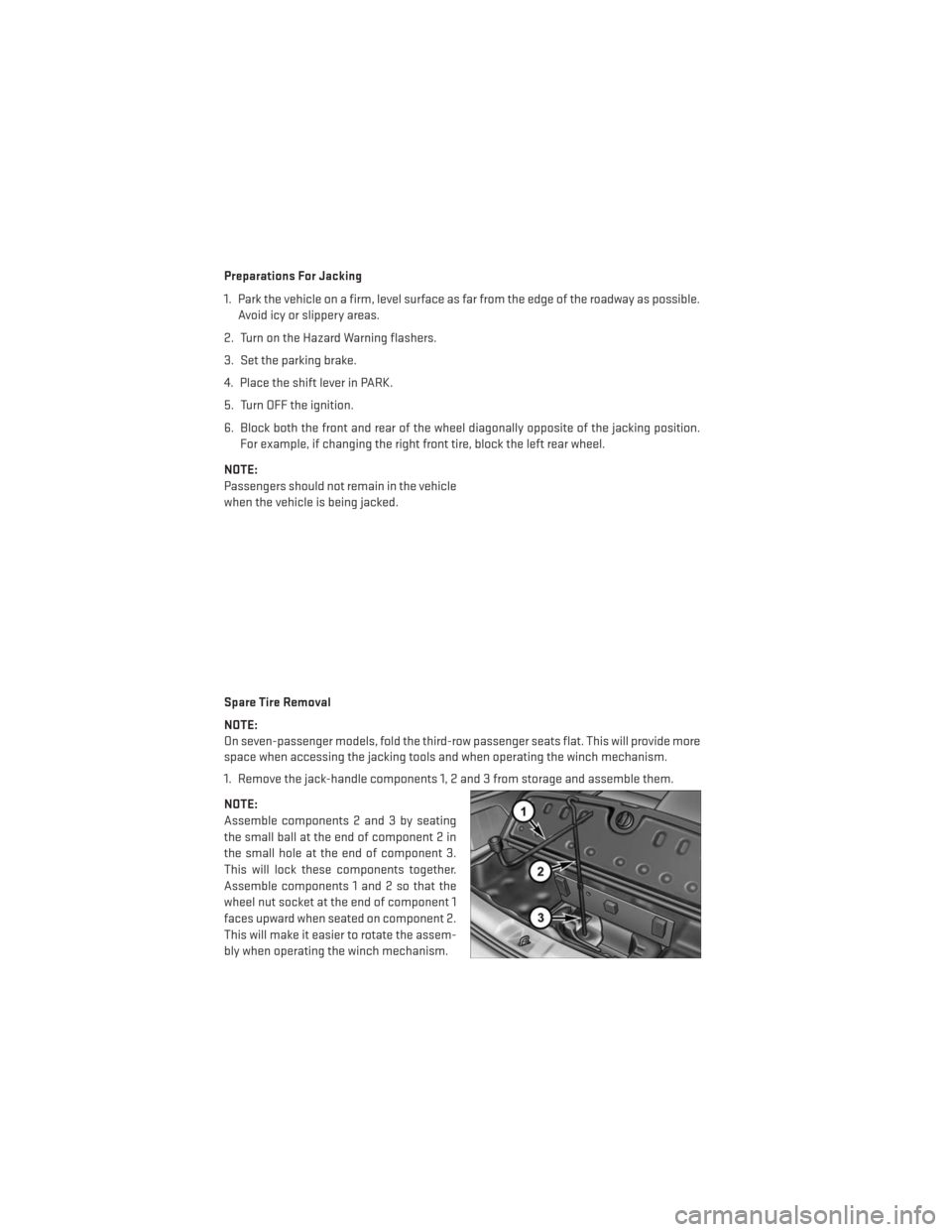
1. Remove the jack-handle components 1, 2 and 3 from storage and assemble them.
NOTE:
Assemble components 2 and 3 by seating
the small ball at the end of component 2 in
the small hole at the end of component 3.
This will lock these components together.
Assemble components 1 and 2 so that the
wheel nut socket at the end of component 1
faces upward when seated on component 2.
This will make it easier to rotate the assem-
bly when operating the winch mechanism.
WHAT TO DO IN EMERGENCIES
74
Page 80 of 116
11. Place the deflated (flat) tire in the cargo area.Do not stow the deflated tire in the
spare tire stowage location. Have the deflated (flat) tire repaired or replaced as soon as
possible.
12. To stow the winch cable and retainer, fit the assembled jack-handle over the winch drive nut. Rotate the jack-handle assembly clockwise until you hear the winch mechanism
click three times. It cannot be over tightened.
13. Stow the jack-handle and jack.
14. Check the tire pressure as soon as possible. Adjust the tire pressure as required.
Road Tire Installation
Vehicles Equipped With Wheel Covers
1. Mount the road tire on the axle.
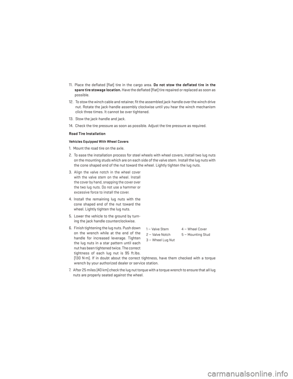
2. To ease the installation process for steel wheels with wheel covers, install two lug nuts on the mounting studs which are on each side of the valve stem. Install the lug nuts with
the cone shaped end of the nut toward the wheel. Lightly tighten the lug nuts.
3.
Align the valve notch in the wheel cover
with the valve stem on the wheel. Install
the cover by hand, snapping the cover over
the two lug nuts. Do not use a hammer or
excessive force to install the cover.
4. Install the remaining lug nuts with the cone shaped end of the nut toward the
wheel. Lightly tighten the lug nuts.
5. Lower the vehicle to the ground by turn- ing the jack handle counterclockwise.
6. Finish tightening the lug nuts. Push down on the wrench while at the end of the
handle for increased leverage. Tighten
the lug nuts in a star pattern until each
nut has been tightened twice. The correct
tightness of each lug nut is 95 ft.lbs.
(130 N·m). If in doubt about the correct tightness, have them checked with a torque
wrench by your authorized dealer or service station.
7. After 25 miles (40 km) check the lug nut torque with a torque wrench to ensure that all lug nuts are properly seated against the wheel.
1 — Valve Stem 4 — Wheel Cover
2 — Valve Notch 5 — Mounting Stud
3 — Wheel Lug Nut
WHAT TO DO IN EMERGENCIES
78
Page 81 of 116
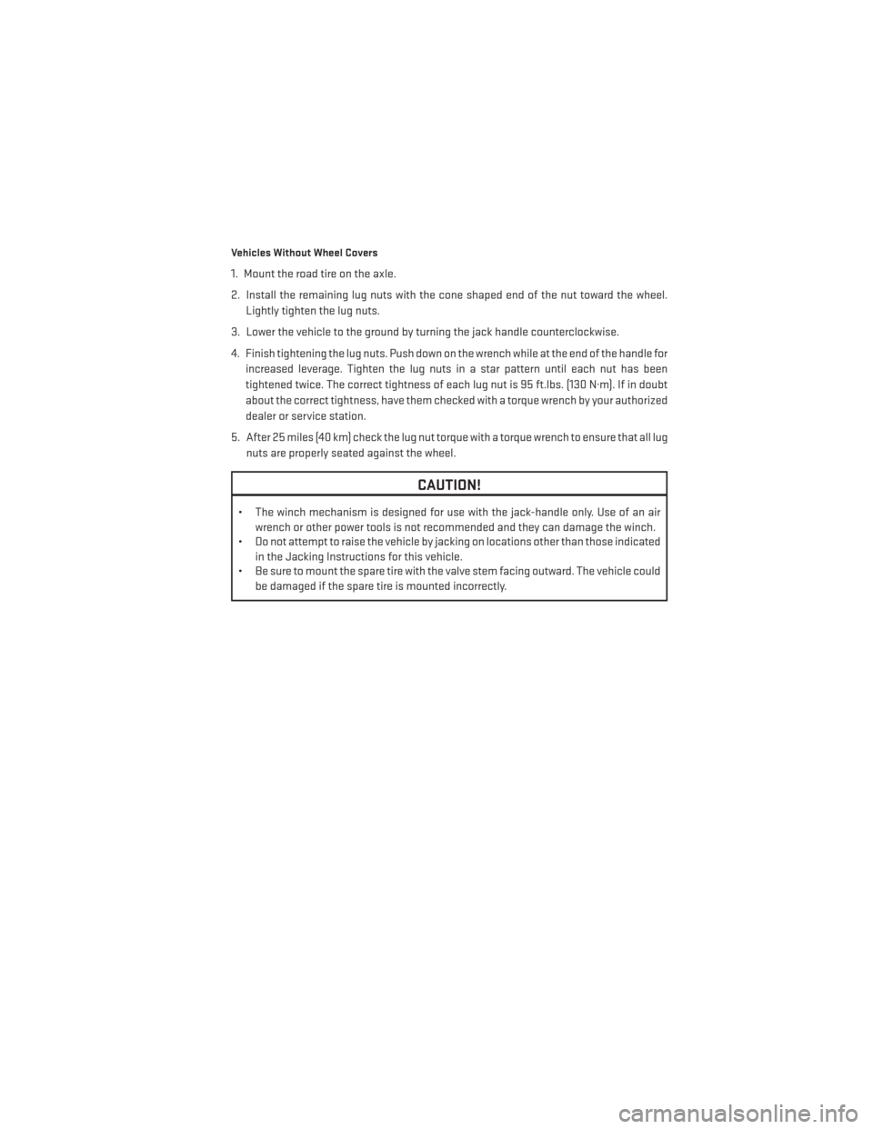
Vehicles Without Wheel Covers
1. Mount the road tire on the axle.
2. Install the remaining lug nuts with the cone shaped end of the nut toward the wheel.Lightly tighten the lug nuts.
3. Lower the vehicle to the ground by turning the jack handle counterclockwise.
4. Finish tightening the lug nuts. Push down on the wrench while at the end of the handle for increased leverage. Tighten the lug nuts in a star pattern until each nut has been
tightened twice. The correct tightness of each lug nut is 95 ft.lbs. (130 N·m). If in doubt
about the correct tightness, have them checked with a torque wrench by your authorized
dealer or service station.
5. After 25 miles (40 km) check the lug nut torque with a torque wrench to ensure that all lug nuts are properly seated against the wheel.
CAUTION!
• The winch mechanism is designed for use with the jack-handle only. Use of an air wrench or other power tools is not recommended and they can damage the winch.
• Do not attempt to raise the vehicle by jacking on locations other than those indicated
in the Jacking Instructions for this vehicle.
• Be sure to mount the spare tire with the valve stem facing outward. The vehicle could
be damaged if the spare tire is mounted incorrectly.
WHAT TO DO IN EMERGENCIES
79
Page 99 of 116
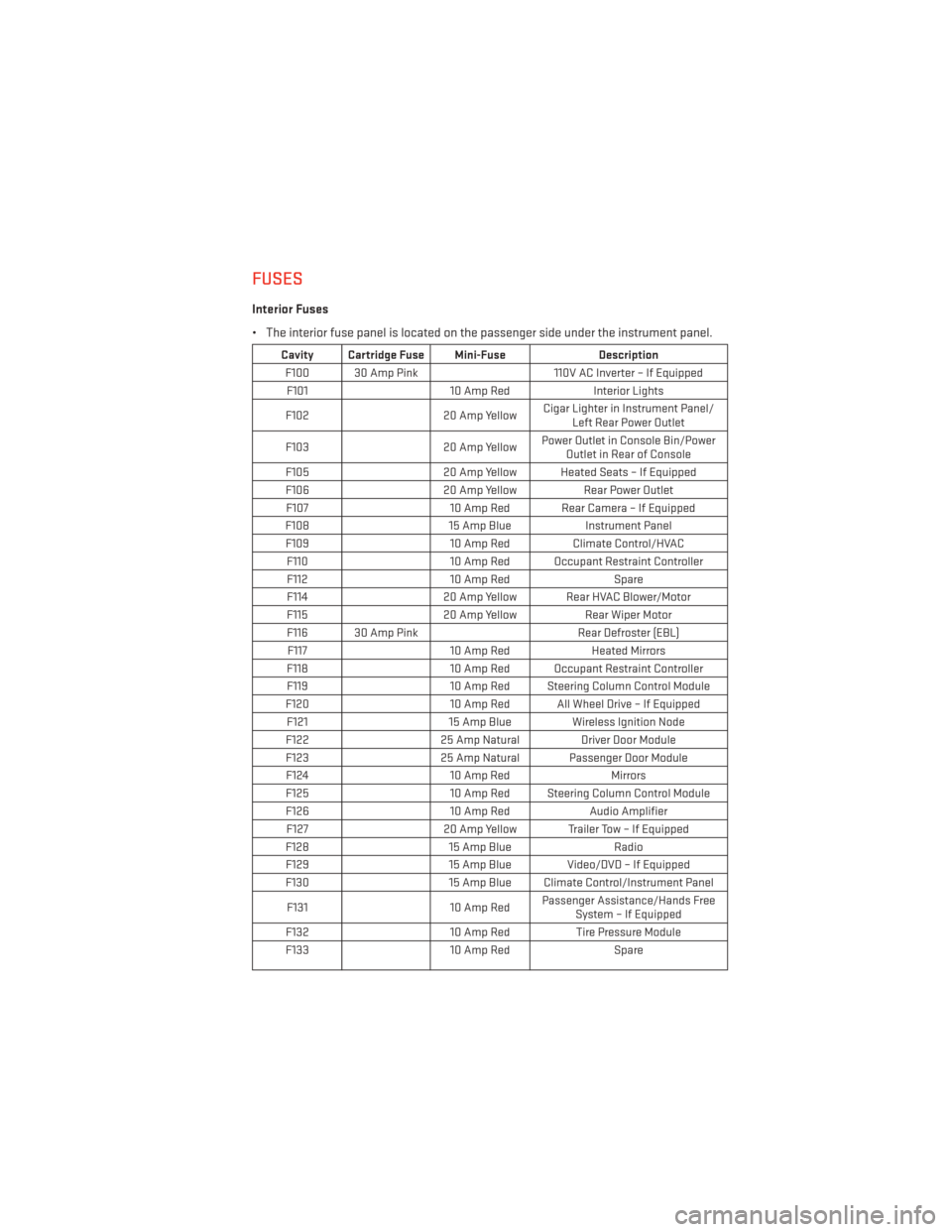
FUSES
Interior Fuses
• The interior fuse panel is located on the passenger side under the instrument panel.
Cavity Cartridge Fuse Mini-FuseDescription
F100 30 Amp Pink 110V AC Inverter – If Equipped
F101 10 Amp RedInterior Lights
F102 20 Amp YellowCigar Lighter in Instrument Panel/
Left Rear Power Outlet
F103 20 Amp YellowPower Outlet in Console Bin/Power
Outlet in Rear of Console
F105 20 Amp Yellow Heated Seats – If Equipped
F106 20 Amp YellowRear Power Outlet
F107 10 Amp Red Rear Camera – If Equipped
F108 15 Amp BlueInstrument Panel
F109 10 Amp RedClimate Control/HVAC
F110 10 Amp Red Occupant Restraint Controller
F112 10 Amp Red Spare
F114 20 Amp Yellow Rear HVAC Blower/Motor
F115 20 Amp YellowRear Wiper Motor
F116 30 Amp Pink Rear Defroster (EBL)
F117 10 Amp RedHeated Mirrors
F118 10 Amp Red Occupant Restraint Controller
F119 10 Amp Red Steering Column Control Module
F120 10 Amp Red All Wheel Drive – If Equipped
F121 15 Amp Blue Wireless Ignition Node
F122 25 Amp Natural Driver Door Module
F123 25 Amp Natural Passenger Door Module
F124 10 Amp RedMirrors
F125 10 Amp Red Steering Column Control Module
F126 10 Amp RedAudio Amplifier
F127 20 Amp Yellow Trailer Tow – If Equipped
F128 15 Amp Blue Radio
F129 15 Amp Blue Video/DVD – If Equipped
F130 15 Amp Blue Climate Control/Instrument Panel
F131 10 Amp RedPassenger Assistance/Hands Free
System – If Equipped
F132 10 Amp RedTire Pressure Module
F133 10 Amp RedSpare
MAINTAINING YOUR VEHICLE
97