starter DODGE JOURNEY 2013 1.G User Guide
[x] Cancel search | Manufacturer: DODGE, Model Year: 2013, Model line: JOURNEY, Model: DODGE JOURNEY 2013 1.GPages: 116, PDF Size: 3.43 MB
Page 13 of 116

Lock or Unlock the Liftgate:
• With a valid Keyless Enter-N-Go™ Key Fobwithin 3 feet (1 meter) of the liftgate, press
the button located to the left of the lift-
gate handle to unlock the liftgate. Press
the button a second time to lock the
liftgate.
NOTE:
Refer to your Owner's Manual on the DVD for
further information.
ENGINE STARTING/STOPPING
Starting
• With a valid Keyless Enter-N-Go™ Key Fob inside the vehicle.
• Place the shift lever in PARK or NEUTRAL.
• While pressing the brake pedal, press the ENGINE START/STOP button once. If the
engine fails to start, the starter will disen-
gage automatically after 10 seconds.
•
To stop the cranking of the engine prior to
the engine starting, press the button again.
NOTE:
In case the ignition switch does not change with the push of a button, the RKE transmitter
(Key Fob) may have a low or dead battery. In this situation a back up method can be used to
operate the ignition switch. Put the nose side of the Key Fob against the ENGINE START/
STOP button and push to operate the ignition switch.
Stopping
• Place the shift lever in PARK.
• Press the ENGINE START/STOP button once. The ignition switch will return to the OFF
position.
•
If the shift lever is not in PARK, the ENGINE START/STOP button must be held for two
seconds and vehicle speed must be above 5 mph (8 km/h) before the engine will shut off.
GETTING STARTED
11
Page 84 of 116

5. Start the engine in the vehicle that has the booster battery, let the engine idle a fewminutes, and then start the engine in the vehicle with the discharged battery. Once the
engine is started, remove the jumper cables in the reverse sequence:
6. Disconnect the negative (-)jumper cable from the remote negative (-)post of the vehicle
with the discharged battery.
7. Disconnect the negative end (-)of the jumper cable from the negative (-)post of the
booster battery.
8. Disconnect the opposite end of the positive (+)jumper cable from the positive (+)post of
the booster battery.
9. Disconnect the positive (+)end of the jumper cable from the remote positive (+)post of
the discharged vehicle.
10. Reinstall the protective cover over the remote positive (+)battery post of the discharged
vehicle.
NOTE:
If frequent jump-starting is required to start your vehicle you should have the battery and
charging system inspected at your authorized dealer.
CAUTION!
• Do not use a portable battery booster pack or any other booster source with a system voltage greater than 12 Volts or damage to the battery, starter motor, alternator or
electrical system may occur.
• Failure to follow these procedures could result in damage to the charging system of the booster vehicle or the discharged vehicle.
• Accessories that can be plugged into the vehicle power outlets draw power from the vehicle’s battery, even when not in use (i.e., cellular phones, etc.). Eventually, if
plugged in long enough, the vehicle’s battery will discharge sufficiently to degrade
battery life and/or prevent the engine from starting.
WHAT TO DO IN EMERGENCIES
82
Page 100 of 116

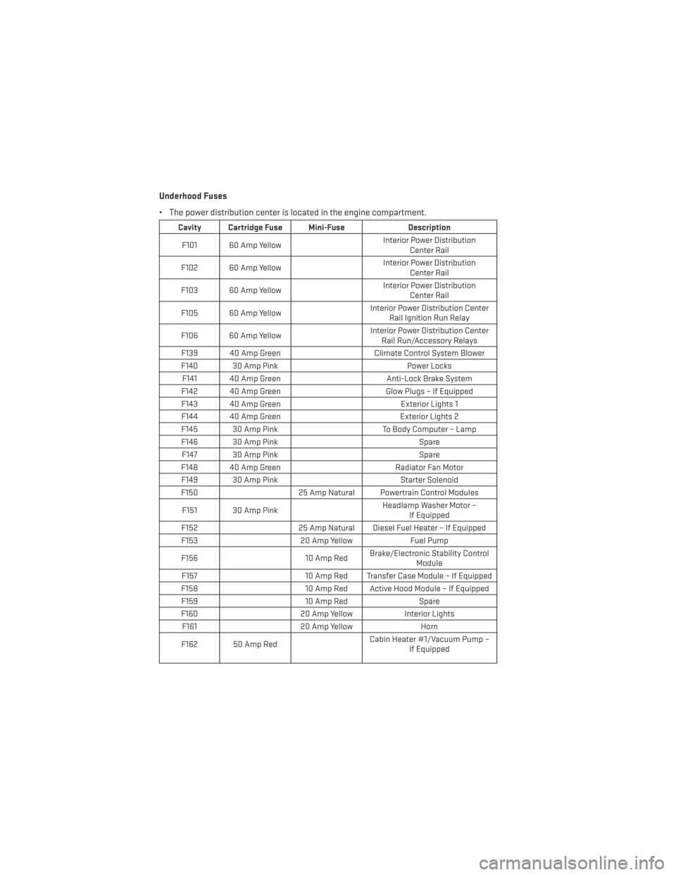
Underhood Fuses
• The power distribution center is located in the engine compartment.
Cavity Cartridge Fuse Mini-FuseDescription
F101 60 Amp Yellow Interior Power Distribution
Center Rail
F102 60 Amp Yellow Interior Power Distribution
Center Rail
F103 60 Amp Yellow Interior Power Distribution
Center Rail
F105 60 Amp Yellow Interior Power Distribution Center
Rail Ignition Run Relay
F106 60 Amp Yellow Interior Power Distribution Center
Rail Run/Accessory Relays
F139 40 Amp Green Climate Control System Blower
F140 30 Amp Pink Power Locks
F141 40 Amp Green Anti-Lock Brake System
F142 40 Amp Green Glow Plugs – If Equipped
F143 40 Amp Green Exterior Lights 1
F144 40 Amp Green Exterior Lights 2
F145 30 Amp Pink To Body Computer – Lamp
F146 30 Amp Pink Spare
F147 30 Amp Pink Spare
F148 40 Amp Green Radiator Fan Motor
F149 30 Amp Pink Starter Solenoid
F150 25 Amp Natural Powertrain Control Modules
F151 30 Amp Pink Headlamp Washer Motor –
If Equipped
F152 25 Amp Natural Diesel Fuel Heater – If Equipped
F153 20 Amp YellowFuel Pump
F156 10 Amp RedBrake/Electronic Stability Control
Module
F157 10 Amp Red Transfer Case Module – If Equipped
F158 10 Amp Red Active Hood Module – If Equipped
F159 10 Amp RedSpare
F160 20 Amp YellowInterior Lights
F161 20 Amp Yellow Horn
F162 50 Amp Red Cabin Heater #1/Vacuum Pump –
If Equipped
MAINTAINING YOUR VEHICLE
98