light DODGE JOURNEY 2014 1.G Owner's Manual
[x] Cancel search | Manufacturer: DODGE, Model Year: 2014, Model line: JOURNEY, Model: DODGE JOURNEY 2014 1.GPages: 124, PDF Size: 3.37 MB
Page 85 of 124
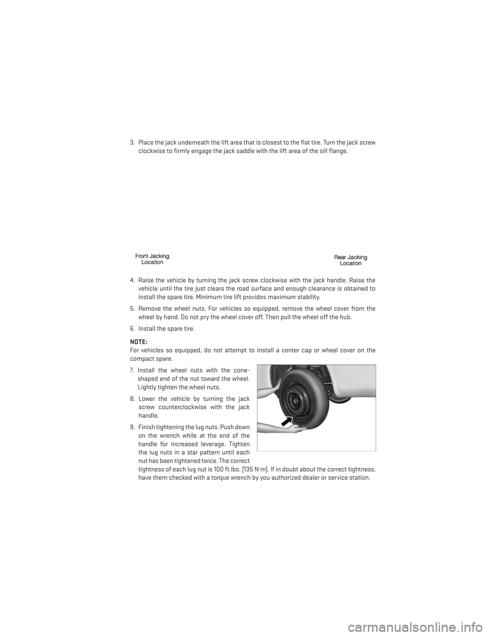
3. Place the jack underneath the lift area that is closest to the flat tire. Turn the jack screwclockwise to firmly engage the jack saddle with the lift area of the sill flange.
4. Raise the vehicle by turning the jack screw clockwise with the jack handle. Raise the vehicle until the tire just clears the road surface and enough clearance is obtained to
install the spare tire. Minimum tire lift provides maximum stability.
5. Remove the wheel nuts. For vehicles so equipped, remove the wheel cover from the wheel by hand. Do not pry the wheel cover off. Then pull the wheel off the hub.
6. Install the spare tire.
NOTE:
For vehicles so equipped, do not attempt to install a center cap or wheel cover on the
compact spare.
7. Install the wheel nuts with the cone- shaped end of the nut toward the wheel.
Lightly tighten the wheel nuts.
8. Lower the vehicle by turning the jack screw counterclockwise with the jack
handle.
9. Finish tightening the lug nuts. Push down on the wrench while at the end of the
handle for increased leverage. Tighten
the lug nuts in a star pattern until each
nut has been tightened twice. The correct
tightness of each lug nut is 100 ft.lbs. (135 N·m). If in doubt about the correct tightness,
have them checked with a torque wrench by you authorized dealer or service station.
WHAT TO DO IN EMERGENCIES
83
Page 86 of 124
10. Lower the jack to its fully closed position.
11. Place the deflated (flat) tire in the cargo area.Do not stow the deflated tire in the spare
tire stowage location. Have the deflated (flat) tire repaired or replaced as soon as
possible.
12. To stow the winch cable and retainer, fit the assembled jack-handle over the winch drive nut. Rotate the jack-handle assembly clockwise until you hear the winch mechanism
click three times. It cannot be over tightened.
13. Stow the jack-handle and jack.
14. Check the tire pressure as soon as possible. Adjust the tire pressure as required.
Road Tire Installation
Vehicles Equipped With Wheel Covers
1. Mount the road tire on the axle.
2. To ease the installation process for steel wheels with wheel covers, install two lug nuts on the mounting studs which are on each side of the valve stem. Install the lug nuts with
the cone shaped end of the nut toward the wheel. Lightly tighten the lug nuts.
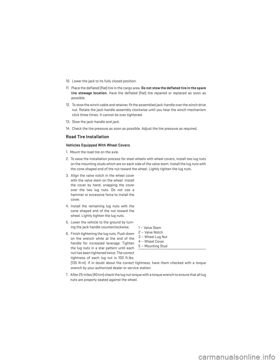
3. Align the valve notch in the wheel cover with the valve stem on the wheel. Install
the cover by hand, snapping the cover
over the two lug nuts. Do not use a
hammer or excessive force to install the
cover.
4. Install the remaining lug nuts with the cone shaped end of the nut toward the
wheel. Lightly tighten the lug nuts.
5. Lower the vehicle to the ground by turn- ing the jack handle counterclockwise.
6. Finish tightening the lug nuts. Push down on the wrench while at the end of the
handle for increased leverage. Tighten
the lug nuts in a star pattern until each
nut has been tightened twice. The correct
tightness of each lug nut is 100 ft.lbs.
(135 N·m). If in doubt about the correct tightness, have them checked with a torque
wrench by your authorized dealer or service station.
7. After 25 miles (40 km) check the lug nut torque with a torque wrench to ensure that all lug nuts are properly seated against the wheel.
1 — Valve Stem
2 — Valve Notch
3 — Wheel Lug Nut
4 — Wheel Cover
5 — Mounting Stud
WHAT TO DO IN EMERGENCIES
84
Page 87 of 124
Vehicles Without Wheel Covers
1. Mount the road tire on the axle.
2. Install the remaining lug nuts with the cone shaped end of the nut toward the wheel.Lightly tighten the lug nuts.
3. Lower the vehicle to the ground by turning the jack handle counterclockwise.
4. Finish tightening the lug nuts. Push down on the wrench while at the end of the handle for increased leverage. Tighten the lug nuts in a star pattern until each nut has been
tightened twice. The correct tightness of each lug nut is 100 ft.lbs. (135 N·m). If in doubt
about the correct tightness, have them checked with a torque wrench by your authorized
dealer or service station.
5. After 25 miles (40 km) check the lug nut torque with a torque wrench to ensure that all lug nuts are properly seated against the wheel.
CAUTION!
• The winch mechanism is designed for use with the jack-handle only. Use of an air wrench or other power tools is not recommended and they can damage the winch.
• Do not attempt to raise the vehicle by jacking on locations other than those indicated
in the Jacking Instructions for this vehicle.
• Be sure to mount the spare tire with the valve stem facing outward. The vehicle could
be damaged if the spare tire is mounted incorrectly.
WHAT TO DO IN EMERGENCIES
85
Page 89 of 124
JUMP-STARTING
• If your vehicle has a discharged battery itcan be jump-started using a set of jumper
cables and a battery in another vehicle or
by using a portable battery booster pack.
• Jump-starting can be dangerous if done improperly so please follow the proce-
dures in this section carefully.
NOTE:
When using a portable battery booster pack
follow the manufacturer's operating instruc-
tions and precautions.
Preparations For Jump-Start
• The battery in your vehicle is located between the left front headlight assembly and the left front wheel splash shield. To allow jump-starting there are remote battery posts
located on the left side of the engine compartment.
• Set the parking brake, shift the automatic transmission into PARK and turn the ignition to LOCK.
• Turn off the heater, radio, and all unnecessary electrical accessories.
• Remove the protective cover over the remote positive (+)battery post. To remove the
cover, press the locking tab and pull upward on the cover.
• If using another vehicle to jump-start the battery, park the vehicle within the jumper cables reach, set the parking brake and make sure the ignition is OFF.
Jump-Starting Procedure
1. Connect the positive (+)end of the jumper cable to the remote positive (+)post of the
vehicle with discharged battery.
2. Connect the opposite end of the positive (+)jumper cable to the positive (+)post of the
booster battery.
3. Connect the negative end (-)of the jumper cable to the negative (-)post of the booster
battery.
WHAT TO DO IN EMERGENCIES
87
Page 100 of 124
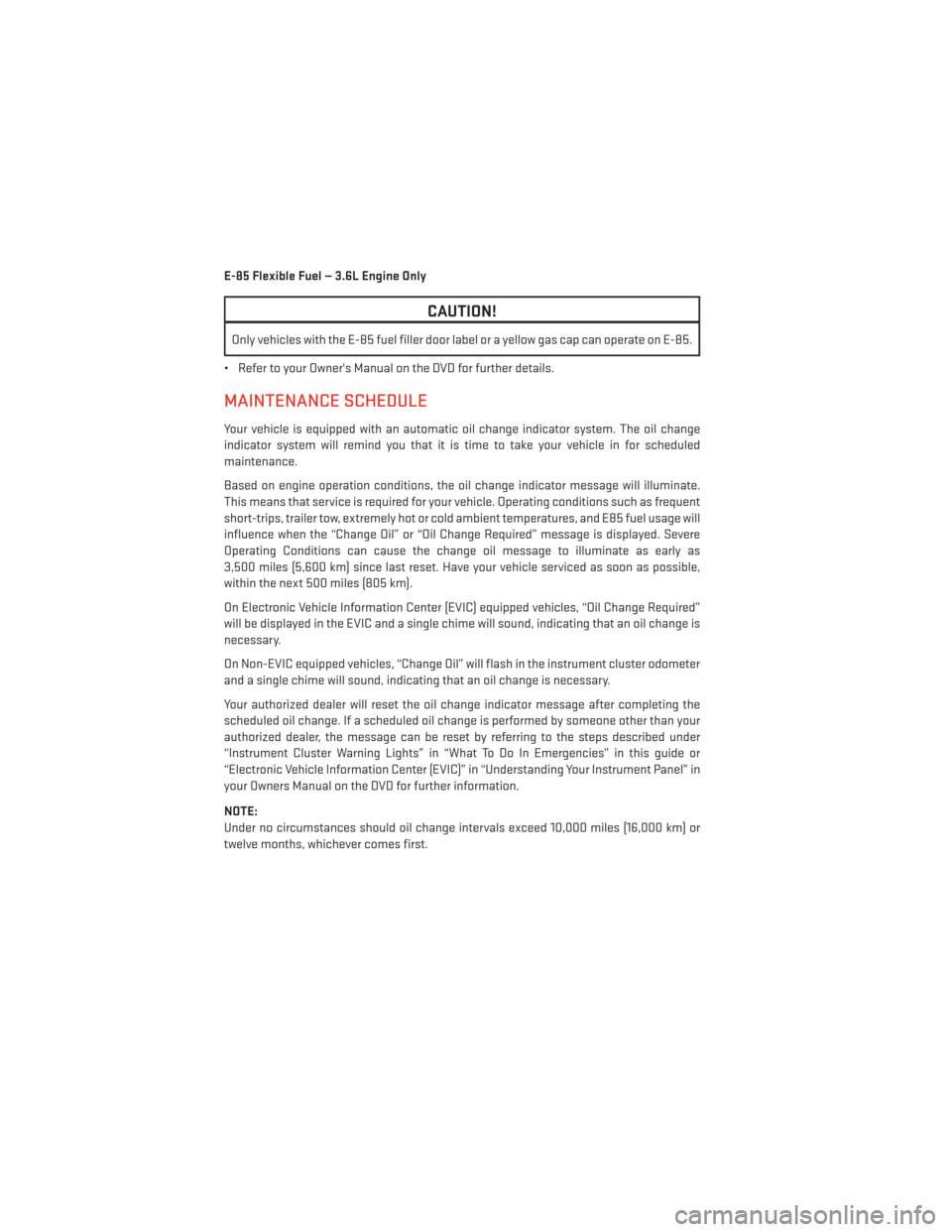
E-85 Flexible Fuel — 3.6L Engine Only
CAUTION!
Only vehicles with the E-85 fuel filler door label or a yellow gas cap can operate on E-85.
• Refer to your Owner's Manual on the DVD for further details.
MAINTENANCE SCHEDULE
Your vehicle is equipped with an automatic oil change indicator system. The oil change
indicator system will remind you that it is time to take your vehicle in for scheduled
maintenance.
Based on engine operation conditions, the oil change indicator message will illuminate.
This means that service is required for your vehicle. Operating conditions such as frequent
short-trips, trailer tow, extremely hot or cold ambient temperatures, and E85 fuel usage will
influence when the “Change Oil” or “Oil Change Required” message is displayed. Severe
Operating Conditions can cause the change oil message to illuminate as early as
3,500 miles (5,600 km) since last reset. Have your vehicle serviced as soon as possible,
within the next 500 miles (805 km).
On Electronic Vehicle Information Center (EVIC) equipped vehicles, “Oil Change Required”
will be displayed in the EVIC and a single chime will sound, indicating that an oil change is
necessary.
On Non-EVIC equipped vehicles, “Change Oil” will flash in the instrument cluster odometer
and a single chime will sound, indicating that an oil change is necessary.
Your authorized dealer will reset the oil change indicator message after completing the
scheduled oil change. If a scheduled oil change is performed by someone other than your
authorized dealer, the message can be reset by referring to the steps described under
“Instrument Cluster Warning Lights” in “What To Do In Emergencies” in this guide or
“Electronic Vehicle Information Center (EVIC)” in “Understanding Your Instrument Panel” in
your Owners Manual on the DVD for further information.
NOTE:
Under no circumstances should oil change intervals exceed 10,000 miles (16,000 km) or
twelve months, whichever comes first.
MAINTAINING YOUR VEHICLE
98
Page 101 of 124
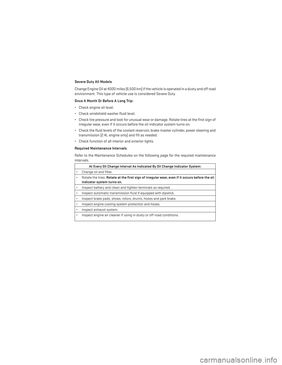
Severe Duty All Models
Change Engine Oil at 4000 miles (6,500 km) if the vehicle is operated in a dusty and off road
environment. This type of vehicle use is considered Severe Duty.
Once A Month Or Before A Long Trip:
• Check engine oil level.
• Check windshield washer fluid level.
• Check tire pressure and look for unusual wear or damage. Rotate tires at the first sign ofirregular wear, even if it occurs before the oil indicator system turns on.
• Check the fluid levels of the coolant reservoir, brake master cylinder, power steering and transmission (2.4L engine only) and fill as needed.
• Check function of all interior and exterior lights.
Required Maintenance Intervals.
Refer to the Maintenance Schedules on the following page for the required maintenance
intervals.
At Every Oil Change Interval As Indicated By Oil Change Indicator System:
• Change oil and filter.
• Rotate the tires. Rotate at the first sign of irregular wear, even if it occurs before the oil
indicator system turns on.
• Inspect battery and clean and tighten terminals as required.
• Inspect automatic transmission fluid if equipped with dipstick.
• Inspect brake pads, shoes, rotors, drums, hoses and park brake.
• Inspect engine cooling system protection and hoses.
• Inspect exhaust system.
• Inspect engine air cleaner if using in dusty or off-road conditions.
MAINTAINING YOUR VEHICLE
99
Page 105 of 124
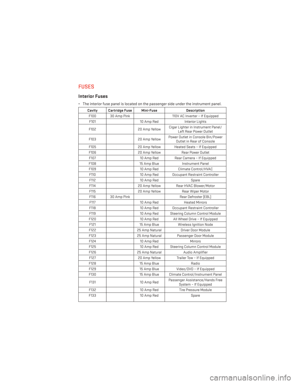
FUSES
Interior Fuses
• The interior fuse panel is located on the passenger side under the instrument panel.
Cavity Cartridge Fuse Mini-FuseDescription
F100 30 Amp Pink 110V AC Inverter – If Equipped
F101 10 Amp RedInterior Lights
F102 20 Amp YellowCigar Lighter in Instrument Panel/
Left Rear Power Outlet
F103 20 Amp YellowPower Outlet in Console Bin/Power
Outlet in Rear of Console
F105 20 Amp Yellow Heated Seats – If Equipped
F106 20 Amp YellowRear Power Outlet
F107 10 Amp Red Rear Camera – If Equipped
F108 15 Amp BlueInstrument Panel
F109 10 Amp RedClimate Control/HVAC
F110 10 Amp Red Occupant Restraint Controller
F112 10 Amp Red Spare
F114 20 Amp Yellow Rear HVAC Blower/Motor
F115 20 Amp YellowRear Wiper Motor
F116 30 Amp Pink Rear Defroster (EBL)
F117 10 Amp RedHeated Mirrors
F118 10 Amp Red Occupant Restraint Controller
F119 10 Amp Red Steering Column Control Module
F120 10 Amp Red All Wheel Drive – If Equipped
F121 15 Amp Blue Wireless Ignition Node
F122 25 Amp Natural Driver Door Module
F123 25 Amp Natural Passenger Door Module
F124 10 Amp RedMirrors
F125 10 Amp Red Steering Column Control Module
F126 25 Amp NaturalAudio Amplifier
F127 20 Amp Yellow Trailer Tow – If Equipped
F128 15 Amp Blue Radio
F129 15 Amp Blue Video/DVD – If Equipped
F130 15 Amp Blue Climate Control/Instrument Panel
F131 10 Amp RedPassenger Assistance/Hands Free
System – If Equipped
F132 10 Amp RedTire Pressure Module
F133 10 Amp RedSpare
MAINTAINING YOUR VEHICLE
103
Page 106 of 124
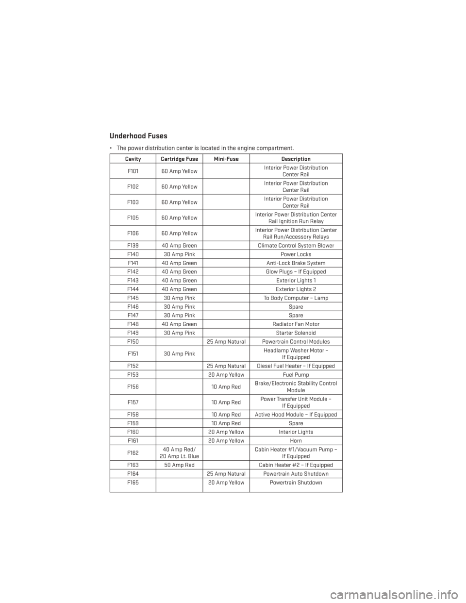
Underhood Fuses
• The power distribution center is located in the engine compartment.
Cavity Cartridge Fuse Mini-FuseDescription
F101 60 Amp Yellow Interior Power Distribution
Center Rail
F102 60 Amp Yellow Interior Power Distribution
Center Rail
F103 60 Amp Yellow Interior Power Distribution
Center Rail
F105 60 Amp Yellow Interior Power Distribution Center
Rail Ignition Run Relay
F106 60 Amp Yellow Interior Power Distribution Center
Rail Run/Accessory Relays
F139 40 Amp Green Climate Control System Blower
F140 30 Amp Pink Power Locks
F141 40 Amp Green Anti-Lock Brake System
F142 40 Amp Green Glow Plugs – If Equipped
F143 40 Amp Green Exterior Lights 1
F144 40 Amp Green Exterior Lights 2
F145 30 Amp Pink To Body Computer – Lamp
F146 30 Amp Pink Spare
F147 30 Amp Pink Spare
F148 40 Amp Green Radiator Fan Motor
F149 30 Amp Pink Starter Solenoid
F150 25 Amp Natural Powertrain Control Modules
F151 30 Amp Pink Headlamp Washer Motor –
If Equipped
F152 25 Amp Natural Diesel Fuel Heater – If Equipped
F153 20 Amp YellowFuel Pump
F156 10 Amp RedBrake/Electronic Stability Control
Module
F157 10 Amp RedPower Transfer Unit Module –
If Equipped
F158 10 Amp Red Active Hood Module – If Equipped
F159 10 Amp RedSpare
F160 20 Amp YellowInterior Lights
F161 20 Amp Yellow Horn
F162 40 Amp Red/
20 Amp Lt. Blue Cabin Heater #1/Vacuum Pump –
If Equipped
F163 50 Amp Red Cabin Heater #2 – If Equipped
F164 25 Amp Natural Powertrain Auto Shutdown
F165 20 Amp Yellow Powertrain Shutdown
MAINTAINING YOUR VEHICLE
104
Page 109 of 124
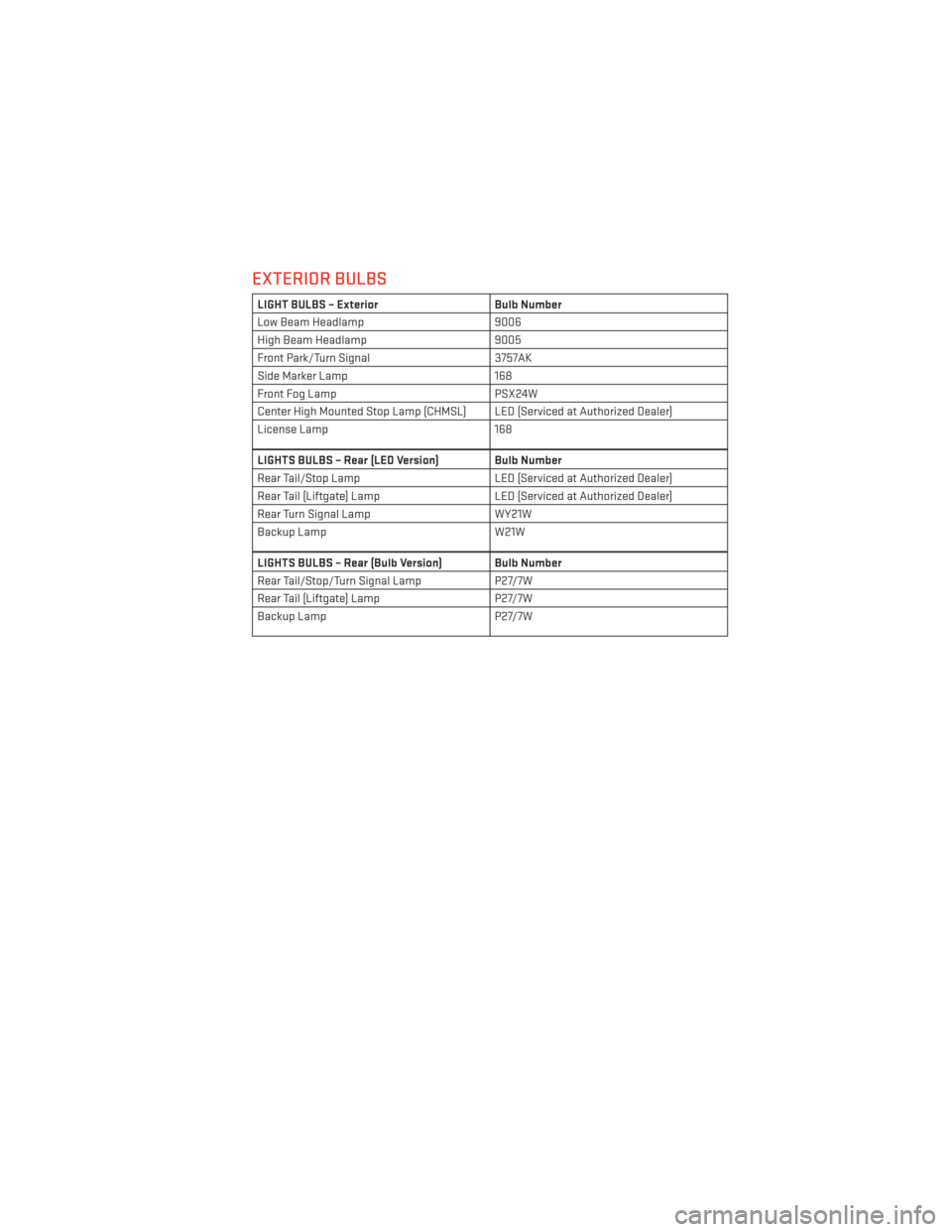
EXTERIOR BULBS
LIGHT BULBS – ExteriorBulb Number
Low Beam Headlamp 9006
High Beam Headlamp 9005
Front Park/Turn Signal 3757AK
Side Marker Lamp 168
Front Fog Lamp PSX24W
Center High Mounted Stop Lamp (CHMSL) LED (Serviced at Authorized Dealer)
License Lamp 168
LIGHTS BULBS – Rear (LED Version) Bulb Number
Rear Tail/Stop Lamp LED (Serviced at Authorized Dealer)
Rear Tail (Liftgate) Lamp LED (Serviced at Authorized Dealer)
Rear Turn Signal Lamp WY21W
Backup Lamp W21W
LIGHTS BULBS – Rear (Bulb Version) Bulb Number
Rear Tail/Stop/Turn Signal LampP27/7W
Rear Tail (Liftgate) Lamp P27/7W
Backup Lamp P27/7W
MAINTAINING YOUR VEHICLE
107
Page 112 of 124
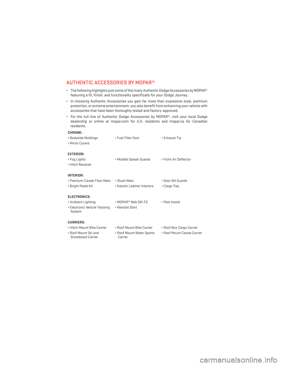
AUTHENTIC ACCESSORIES BY MOPAR®
• The following highlights just some of the many Authentic Dodge Accessories by MOPAR®featuring a fit, finish, and functionality specifically for your Dodge Journey.
• In choosing Authentic Accessories you gain far more than expressive style, premium protection, or extreme entertainment, you also benefit from enhancing your vehicle with
accessories that have been thoroughly tested and factory-approved.
• For the full line of Authentic Dodge Accessories by MOPAR®, visit your local Dodge dealership or online at mopar.com for U.S. residents and mopar.ca for Canadian
residents.
CHROME:
• Bodyside Moldings • Fuel Filler Door • Exhaust Tip
• Mirror Covers
EXTERIOR:
• Fog Lights • Molded Splash Guards • Front Air Deflector
• Hitch Receiver
INTERIOR:
• Premium Carpet Floor Mats • Slush Mats • Door Sill Guards
• Bright Pedal Kit • Katzkin Leather Interiors • Cargo Tray
ELECTRONICS:
• Ambient Lighting • MOPAR® Web (Wi-Fi) • Park Assist
• Electronic Vehicle Tracking System • Remote Start
CARRIERS:
• Hitch-Mount Bike Carrier • Roof Mount Bike Carrier • Roof Box Cargo Carrier
• Roof Mount Ski and Snowboard Carrier • Roof Mount Water Sports
Carrier • Roof Mount Canoe Carrier
MOPAR® ACCESSORIES
110