seats DODGE JOURNEY 2014 1.G User Guide
[x] Cancel search | Manufacturer: DODGE, Model Year: 2014, Model line: JOURNEY, Model: DODGE JOURNEY 2014 1.GPages: 124, PDF Size: 3.37 MB
Page 3 of 124
INTRODUCTION/WELCOME
WELCOME FROM CHRYSLER GROUP LLC . . . 2
CONTROLS AT A GLANCE
DRIVER COCKPIT................4
INSTRUMENT CLUSTER ............6
GETTING STARTED
KEYFOB .....................8
REMOTE START.................9
KEYLESS ENTER-N-GO™ ............9
VEHICLE SECURITY ALARM ..........13
SEATBELT ...................13
SUPPLEMENTAL RESTRAINT
SYSTEM (SRS) — AIR BAGS ...........14
CHILD RESTRAINTS ..............15
FRONT SEATS .................21
REARSEATS ..................23
HEATEDSEATS ................25
HEATED STEERING WHEEL ..........26
TILT/TELESCOPING STEERING COLUMN . . . 27
OPERATING YOUR VEHICLE
ENGINE BREAK-IN RECOMMENDATIONS . . . 28
TURN SIGNAL/WIPER/WASHER/HIGH BEAM
LEVER ......................28
HEADLIGHT SWITCH ..............29
SPEED CONTROL ................30
CLIMATE CONTROL ..............33
PARKVIEW® REAR BACK-UP CAMERA ....35
POWER SUNROOF ...............36
WIND BUFFETING ................37
ELECTRONICS
YOUR VEHICLE'S SOUND SYSTEM ......38
IDENTIFYING YOUR RADIO ...........40
Uconnect® 4.3 & 4.3S AT A GLANCE .....41
Uconnect® 8.4 & 8.4N AT A GLANCE .....42
RADIO ......................44
SiriusXM SATELLITE RADIO ..........45
iPod®/CD/AUX CONTROLS ..........48
GARMIN® NAVIGATION .............50
SiriusXM TRAVEL LINK .............53
PLAYING iPod®/USB/MP3 DEVICES .....54
Uconnect® PHONE ...............55
Uconnect® VOICE COMMAND
(8.4&8.4NONLY) ...............60
VIDEO ENTERTAINMENT SYSTEM (VES™) . . 63
STEERING WHEEL AUDIO CONTROLS ....64
ELECTRONIC VEHICLE INFORMATION
CENTER (EVIC) .................64 PROGRAMMABLE FEATURES
.........65
UNIVERSAL GARAGE DOOR OPENER
(HomeLink®) ..................66
POWER INVERTER ...............69
POWER OUTLETS ...............70
UTILITY
TRAILER TOWING WEIGHTS (MAXIMUM
TRAILERWEIGHTRATINGS) ..........71
RECREATIONAL TOWING (BEHIND
MOTORHOME, ETC.) ..............72
WHAT TO DO IN EMERGENCIES
ROADSIDE ASSISTANCE ............73
INSTRUMENT CLUSTER WARNING LIGHTS . . 73
IF YOUR ENGINE OVERHEATS .........79
JACKING AND TIRE CHANGING ........80
JUMP-STARTING ................87
SHIFT LEVER OVERRIDE ...........89
TOWING A DISABLED VEHICLE ........90
FREEING A STUCK VEHICLE ..........91
EVENT DATA RECORDER (EDR) ........92
MAINTAINING YOUR VEHICLE
OPENING THE HOOD..............93
ENGINE COMPARTMENT ...........94
FLUIDS AND CAPACITIES ...........96
MAINTENANCE SCHEDULE ..........98
MAINTENANCE RECORD ...........102
FUSES .....................103
TIRE PRESSURES ...............105
WHEEL AND WHEEL TRIM CARE ......106
EXTERIOR BULBS ...............107
CONSUMER ASSISTANCE
CHRYSLER GROUP LLC
CUSTOMER CENTER .............108
CHRYSLER CANADA INC.
CUSTOMER CENTER .............108
ASSISTANCE FOR THE HEARING
IMPAIRED ...................108
PUBLICATIONS ORDERING ..........108
REPORTING SAFETY DEFECTS IN THE
UNITEDSTATES ................109
MOPAR® ACCESSORIES
AUTHENTIC ACCESSORIES BY MOPAR® . . . 110
FREQUENTLY ASKED QUESTIONS
FREQUENTLY ASKED QUESTIONS .......111
INDEX....................112
TABLE OF CONTENTS
Page 17 of 124
WARNING!
• Relying on the air bags alone could lead to more severe injuries in a collision. The airbags work with your seat belt to restrain you properly. In some collisions, the air bags
won't deploy at all. Always wear your seat belts even though you have air bags.
• Being too close to the steering wheel or instrument panel during Advanced Front Air
Bag deployment could cause serious injury, including death. Air bags need room to
inflate. Sit back, comfortably extending your arms to reach the steering wheel or
instrument panel.
• Supplemental Side Air Bag Inflatable Curtains and Supplemental Seat-Mounted Side
Air Bags need room to inflate. Do not lean against the door or window. Sit upright in
the center of the seat.
• Being too close to the Supplemental Side Air Bag Inflatable Curtain and/or Seat-
Mounted Side Air Bag during deployment could cause you to be severely injured or
killed.
• Do not drive your vehicle after the air bags have deployed. If you are involved in
another collision, the air bags will not be in place to protect you.
• After any collision, the vehicle should be taken to an authorized dealer immediately.
CHILD RESTRAINTS
Children 12 years or younger should ride properly buckled up in a rear seat, if available.
According to crash statistics, children are safer when properly restrained in the rear seats
rather than in the front.
Every state in the United States and all Canadian provinces require that small children ride
in proper restraint systems. This is the law, and you can be prosecuted for ignoring it.
NOTE:
• For additional information, refer to www.seatcheck.org or call 1–866–SEATCHECK (1–866–732–8243).
• Canadian residents, should refer to Transport Canada’s website for additional informa- tion: http://www.tc.gc.ca/eng/roadsafety/safedrivers-childsafety-index-53.htm
GETTING STARTED
15
Page 19 of 124
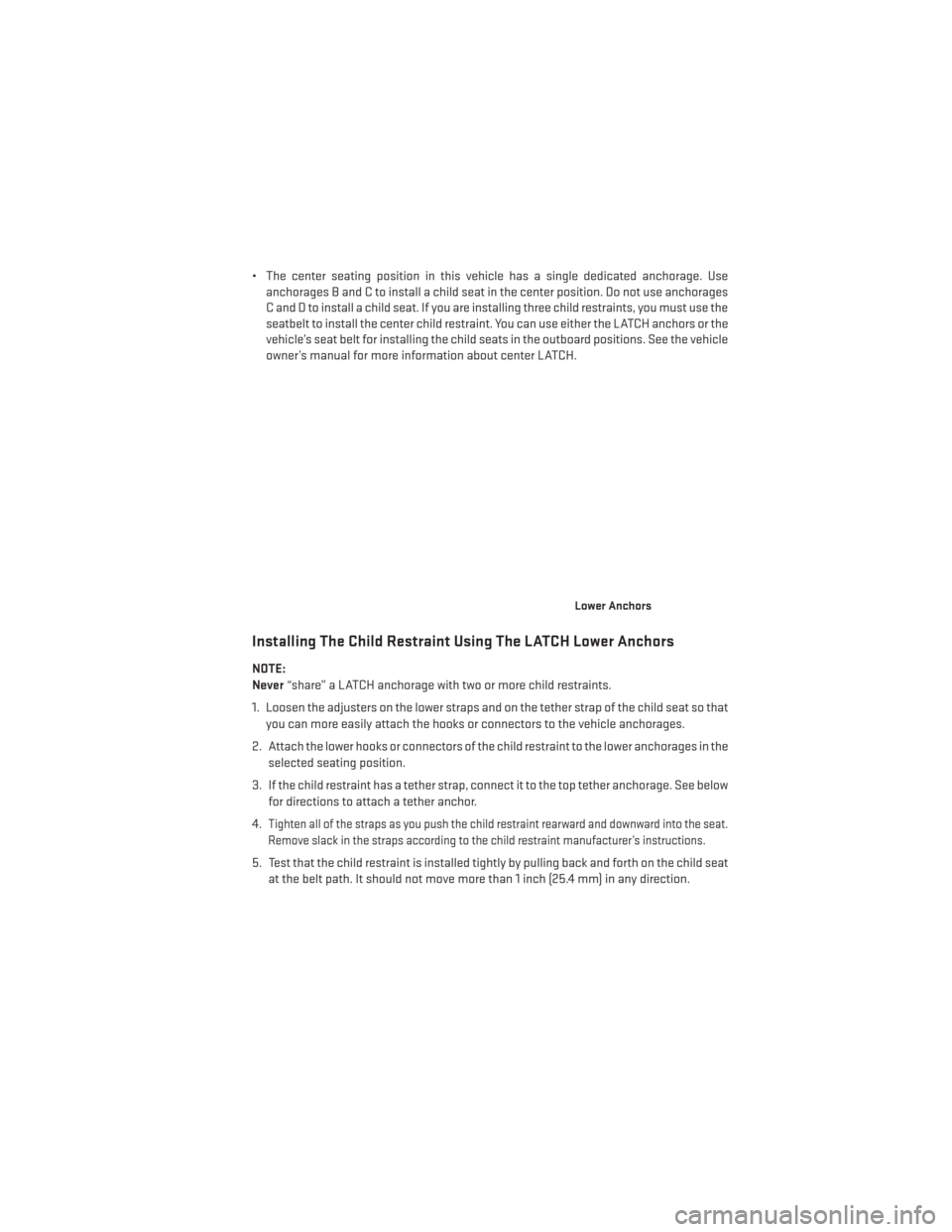
• The center seating position in this vehicle has a single dedicated anchorage. Useanchorages B and C to install a child seat in the center position. Do not use anchorages
C and D to install a child seat. If you are installing three child restraints, you must use the
seatbelt to install the center child restraint. You can use either the LATCH anchors or the
vehicle’s seat belt for installing the child seats in the outboard positions. See the vehicle
owner’s manual for more information about center LATCH.
Installing The Child Restraint Using The LATCH Lower Anchors
NOTE:
Never “share” a LATCH anchorage with two or more child restraints.
1. Loosen the adjusters on the lower straps and on the tether strap of the child seat so that you can more easily attach the hooks or connectors to the vehicle anchorages.
2. Attach the lower hooks or connectors of the child restraint to the lower anchorages in the selected seating position.
3. If the child restraint has a tether strap, connect it to the top tether anchorage. See below for directions to attach a tether anchor.
4.
Tighten all of the straps as you push the child restraint rearward and downward into the seat.
Remove slack in the straps according to the child restraint manufacturer’s instructions.
5. Test that the child restraint is installed tightly by pulling back and forth on the child seat at the belt path. It should not move more than 1 inch (25.4 mm) in any direction.
Lower Anchors
GETTING STARTED
17
Page 22 of 124
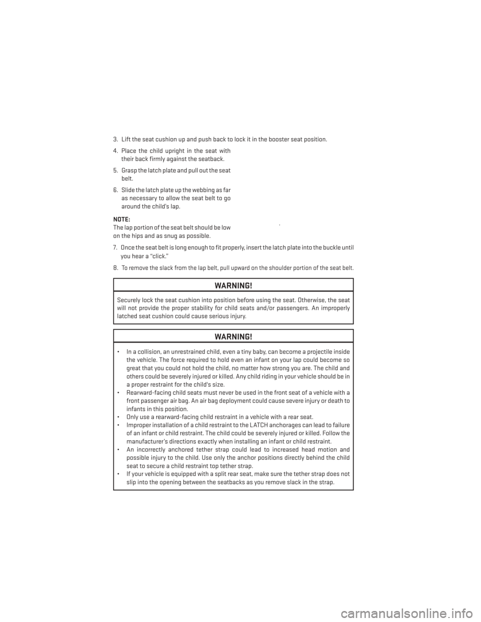
3. Lift the seat cushion up and push back to lock it in the booster seat position.
4. Place the child upright in the seat withtheir back firmly against the seatback.
5. Grasp the latch plate and pull out the seat belt.
6. Slide the latch plate up the webbing as far as necessary to allow the seat belt to go
around the child’s lap.
NOTE:
The lap portion of the seat belt should be low
on the hips and as snug as possible.
7. Once the seat belt is long enough to fit properly, insert the latch plate into the buckle until you hear a “click.”
8.
To remove the slack from the lap belt, pull upward on the shoulder portion of the seat belt.
WARNING!
Securely lock the seat cushion into position before using the seat. Otherwise, the seat
will not provide the proper stability for child seats and/or passengers. An improperly
latched seat cushion could cause serious injury.
WARNING!
• In a collision, an unrestrained child, even a tiny baby, can become a projectile inside the vehicle. The force required to hold even an infant on your lap could become so
great that you could not hold the child, no matter how strong you are. The child and
others could be severely injured or killed. Any child riding in your vehicle should be in
a proper restraint for the child's size.
• Rearward-facing child seats must never be used in the front seat of a vehicle with a
front passenger air bag. An air bag deployment could cause severe injury or death to
infants in this position.
• Only use a rearward-facing child restraint in a vehicle with a rear seat.
• Improper installation of a child restraint to the LATCH anchorages can lead to failure
of an infant or child restraint. The child could be severely injured or killed. Follow the
manufacturer’s directions exactly when installing an infant or child restraint.
• An incorrectly anchored tether strap could lead to increased head motion and
possible injury to the child. Use only the anchor positions directly behind the child
seat to secure a child restraint top tether strap.
• If your vehicle is equipped with a split rear seat, make sure the tether strap does not
slip into the opening between the seatbacks as you remove slack in the strap.
GETTING STARTED
20
Page 23 of 124
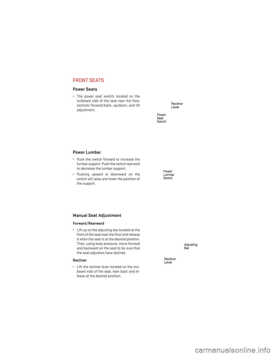
FRONT SEATS
Power Seats
• The power seat switch, located on theoutboard side of the seat near the floor,
controls forward/back, up/down, and tilt
adjustment.
Power Lumbar
• Push the switch forward to increase thelumbar support. Push the switch rearward
to decrease the lumbar support.
• Pushing upward or downward on the switch will raise and lower the position of
the support.
Manual Seat Adjustment
Forward/Rearward
• Lift up on the adjusting bar located at thefront of the seat near the floor and release
it when the seat is at the desired position.
Then, using body pressure, move forward
and backward on the seat to be sure that
the seat adjusters have latched.
Recliner
• Lift the recliner lever located on the out-board side of the seat, lean back and re-
lease at the desired position.
GETTING STARTED
21
Page 25 of 124
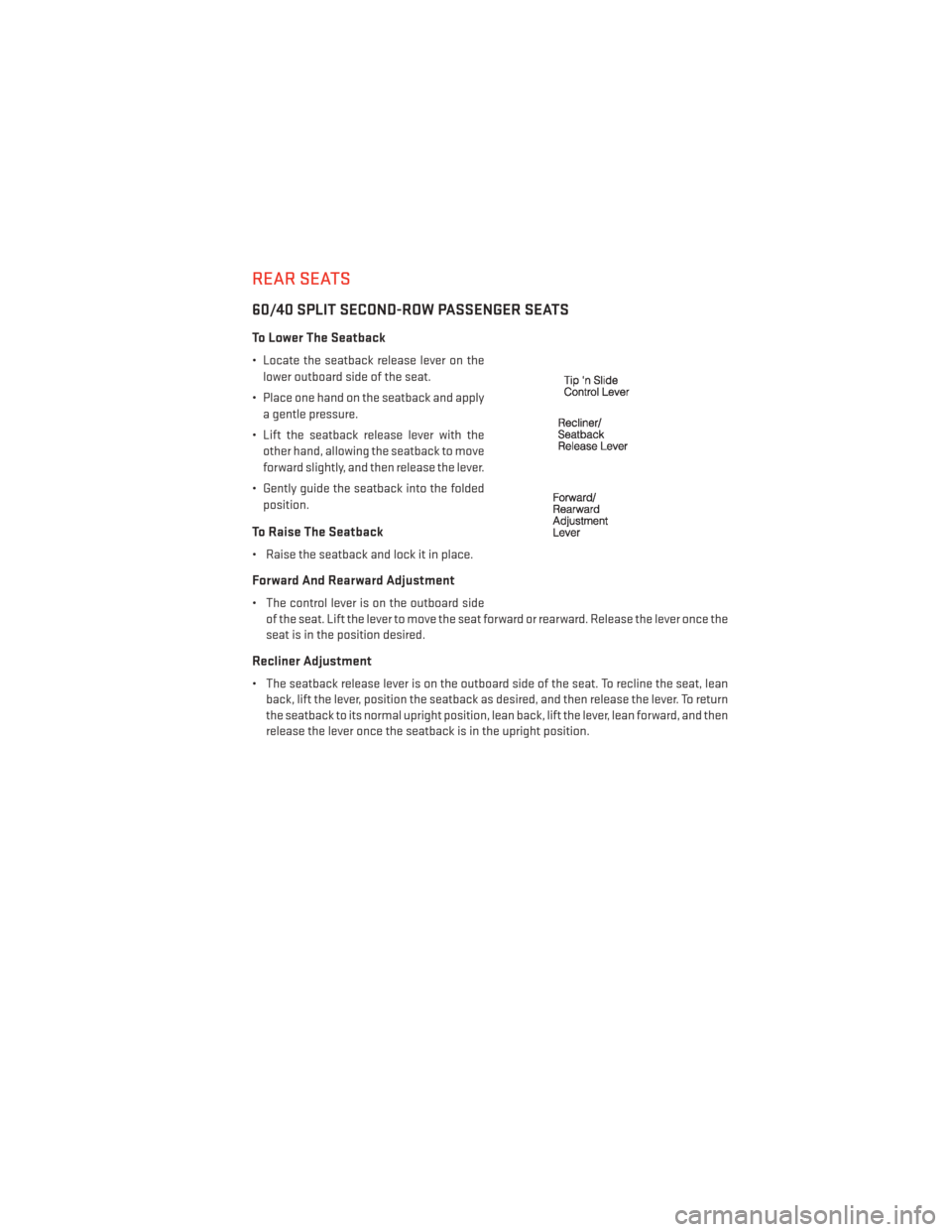
REAR SEATS
60/40 SPLIT SECOND-ROW PASSENGER SEATS
To Lower The Seatback
• Locate the seatback release lever on thelower outboard side of the seat.
• Place one hand on the seatback and apply a gentle pressure.
• Lift the seatback release lever with the other hand, allowing the seatback to move
forward slightly, and then release the lever.
• Gently guide the seatback into the folded position.
To Raise The Seatback
• Raise the seatback and lock it in place.
Forward And Rearward Adjustment
• The control lever is on the outboard side of the seat. Lift the lever to move the seat forward or rearward. Release the lever once the
seat is in the position desired.
Recliner Adjustment
• The seatback release lever is on the outboard side of the seat. To recline the seat, leanback, lift the lever, position the seatback as desired, and then release the lever. To return
the seatback to its normal upright position, lean back, lift the lever, lean forward, and then
release the lever once the seatback is in the upright position.
GETTING STARTED
23
Page 26 of 124
STADIUM Tip ’n Slide™ (EASY ENTRY/EXIT SEAT) — SEVEN PASSENGER
MODELS
To Move The Second-Row Passenger Seat Forward
NOTE:
Raise the 20% seatback/armrest before moving the 60% seat to allow for full seat travel.
• To allow passengers to easily enter or exit the third-row passenger seats move the Tip ’nSlide™ control lever on the upper outboard side of the seatback forward, and in one fluid
motion, the seat cushion flips upward and the seat moves forward on its tracks.
To Unfold And Move The Second-Row
Passenger Seat Rearward
• Move the seatback rearward until it locks in place and then continue sliding the
seat rearward on its tracks until it locks in
place.
• Push the seat cushion downward to lock it in place.
• Adjust the seat track position as desired.
50/50 SPLIT THIRD-ROW PASSENGER SEATS WITH FOLD-FLAT
FEATURE
To Fold The Seat
• With the second-row passenger seat fully upright, pull the latch release-loop located at the top of the seatback upward, push the seat forward slightly, and release the release-
loop. Then, continue to push the seat forward. The head restraints will fold automatically
as the seat moves forward.
To Unfold The Seat
• Grasp the assist strap loop on the seatback and pull it toward you to raise the seatback.Continue to raise the seatback until it locks in place. Then, raise the head restraint to lock
it in place.
• To lock the seatback in a reclined position, pull the latch release-loop located at the top of the seatback upward, allow the seatback to recline, then release the release-loop.
GETTING STARTED
24
Page 27 of 124
WARNING!
• Be certain that the seatback is locked securely into position. Otherwise, the seat willnot provide the proper stability for child seats and/or passengers. An improperly
latched seat could cause you and others to be severely injured or killed.
• Do not allow a passenger to sit in a third row seat without having the head restraint
unfolded and locked in place or seatback(s) folded flat. Failure to follow this warning
may result in the passengers being severely injured or killed in the event of a collision.
• Do not drive the vehicle with the seat in the Tip 'n Slide™ position, as it is only intended for entering and exiting the third row seats. Failure to follow this warning may result
in you and others being severely injured or killed.
• Be certain that the seatback and seat are locked securely into position. Otherwise,
the seat will not provide the proper stability for child seats and/or passengers. An
improperly latched seat could cause you or others to be severely injured or killed.
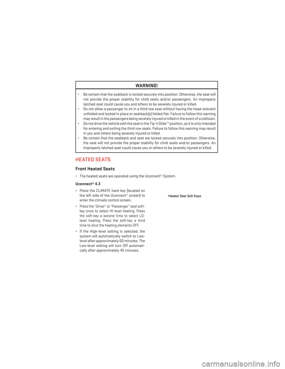
HEATED SEATS
Front Heated Seats
• The heated seats are operated using the Uconnect® System.
Uconnect® 4.3
• Press the CLIMATE hard-key (located onthe left side of the Uconnect® screen) to
enter the climate control screen.
•
Press the “Driver” or “Passenger” seat soft-
key once to select HI-level heating. Press
the soft-key a second time to select LO-
level heating. Press the soft-key a third
time to shut the heating elements OFF.
• If the High-level setting is selected, the system will automatically switch to Low-
level after approximately 60 minutes. The
Low-level setting will turn Off automati-
cally after approximately 45 minutes.
GETTING STARTED
25
Page 67 of 124
Compass Calibration
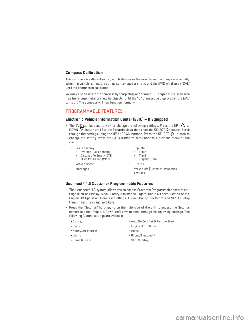
This compass is self-calibrating, which eliminates the need to set the compass manually.
When the vehicle is new, the compass may appear erratic and the EVIC will display “CAL”
until the compass is calibrated.
You may also calibrate the compass by completing one or more 360 degree turns (in an area
free from large metal or metallic objects) until the “CAL” message displayed in the EVIC
turns off. The compass will now function normally.
PROGRAMMABLE FEATURES
Electronic Vehicle Information Center (EVIC) — If Equipped
• The EVIC can be used to view or change the following settings. Press the UPor
DOWN
button until System Setup displays, then press the SELECTbutton. Scroll
through the settings using the UP or DOWN buttons. Press the SELECT
button to
change the setting. Press the BACK button to scroll back to a previous menu or sub
menu.
• Fuel Economy • Average Fuel Economy
• Distance To Empty (DTE)
• Miles Per Gallon (MPG) • Trip Info
• Trip A
• Trip B
• Elapsed Time
• Vehicle Speed • Tire PSI
• Messages •
Vehicle Info (Customer Information
Features)
Uconnect® 4.3 Customer Programmable Features
• The Uconnect® 4.3 system allows you to access Customer Programmable feature set- tings such as Display, Clock, Safety/Assistance, Lights, Doors & Locks, Heated Seats,
Engine Off Operation, Compass Settings, Audio, Phone/ Bluetooth® and SIRIUS Setup
through hard-keys and soft-keys.
• Press the “Settings” hard-key to on the right side of the unit to access the Settings screen, use the “Page Up/Down” soft-keys to scroll through the following settings. The
following feature settings are available:
• Display • Auto On Comfort & Remote Start
• Clock • Engine Off Options
• Safety/Assistance • Audio
• Lights • Phone/Bluetooth®
• Doors & Locks • SIRIUS Setup
ELECTRONICS
65
Page 68 of 124
Uconnect® 8.4 Customer Programmable Features
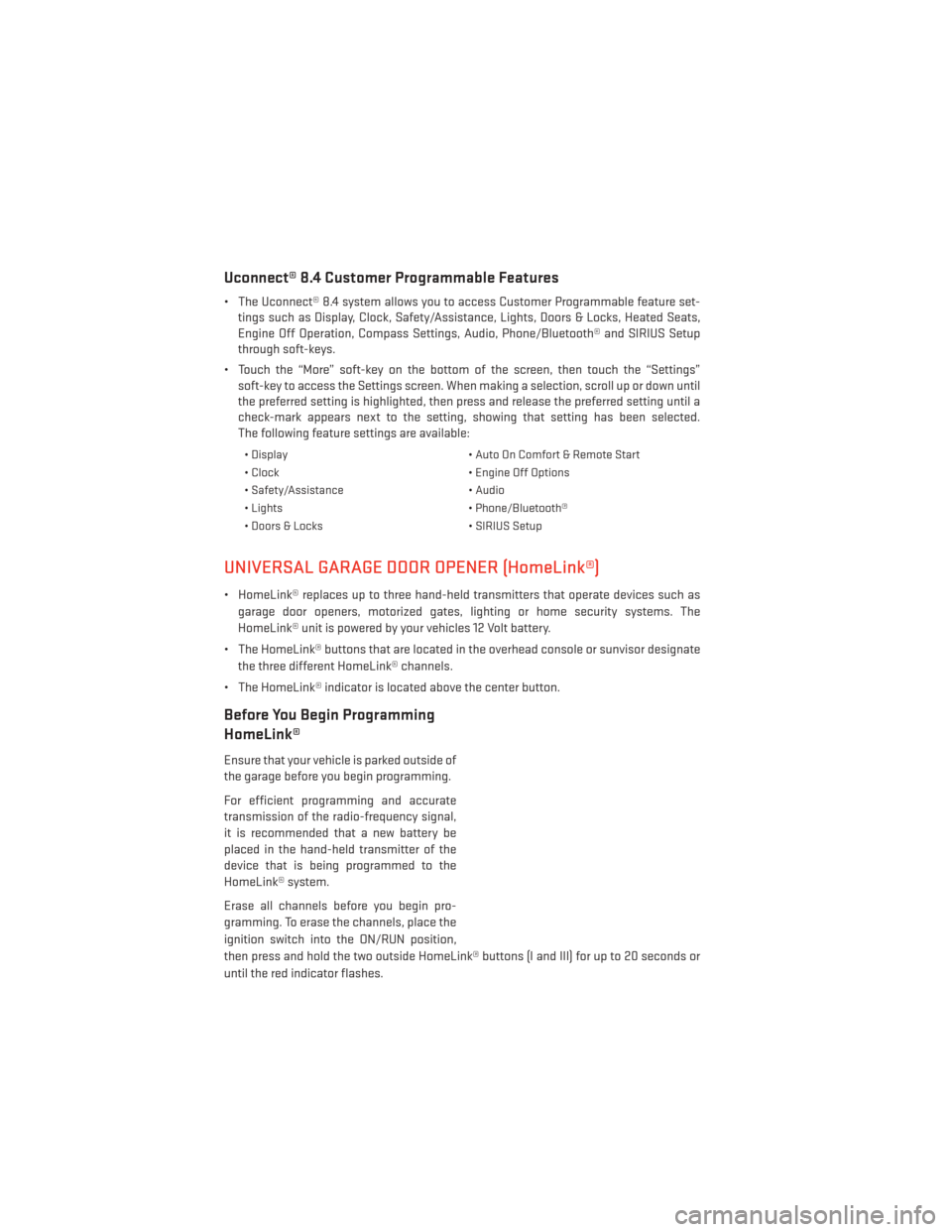
• The Uconnect® 8.4 system allows you to access Customer Programmable feature set-tings such as Display, Clock, Safety/Assistance, Lights, Doors & Locks, Heated Seats,
Engine Off Operation, Compass Settings, Audio, Phone/Bluetooth® and SIRIUS Setup
through soft-keys.
• Touch the “More” soft-key on the bottom of the screen, then touch the “Settings” soft-key to access the Settings screen. When making a selection, scroll up or down until
the preferred setting is highlighted, then press and release the preferred setting until a
check-mark appears next to the setting, showing that setting has been selected.
The following feature settings are available:
• Display • Auto On Comfort & Remote Start
• Clock • Engine Off Options
• Safety/Assistance • Audio
• Lights • Phone/Bluetooth®
• Doors & Locks • SIRIUS Setup
UNIVERSAL GARAGE DOOR OPENER (HomeLink®)
• HomeLink® replaces up to three hand-held transmitters that operate devices such as
garage door openers, motorized gates, lighting or home security systems. The
HomeLink® unit is powered by your vehicles 12 Volt battery.
• The HomeLink® buttons that are located in the overhead console or sunvisor designate the three different HomeLink® channels.
• The HomeLink® indicator is located above the center button.
Before You Begin Programming
HomeLink®
Ensure that your vehicle is parked outside of
the garage before you begin programming.
For efficient programming and accurate
transmission of the radio-frequency signal,
it is recommended that a new battery be
placed in the hand-held transmitter of the
device that is being programmed to the
HomeLink® system.
Erase all channels before you begin pro-
gramming. To erase the channels, place the
ignition switch into the ON/RUN position,
then press and hold the two outside HomeLink® buttons (I and III) for up to 20 seconds or
until the red indicator flashes.
ELECTRONICS
66