DODGE JOURNEY 2015 1.G Owners Manual
Manufacturer: DODGE, Model Year: 2015, Model line: JOURNEY, Model: DODGE JOURNEY 2015 1.GPages: 648
Page 371 of 648
Disc Errors
If the DVD player is unable to read the disc, a#Disc Error#
message is displayed on the Radio display and the disc is
automatically ejected. A dirty, damaged, or incompatible
disc format are all potential causes for a#Disc Error#
message.
If a disc has a damaged track which results in audible or
visible errors that persists for 2.0 seconds, the DVD player
will attempt to continue playing the disc by skipping
forward 1.0 to 3.0 seconds at a time. If the end of the disc
is reached, the DVD player will return to the beginning of
the disc and attempt to play the start of the first track.
The DVD player may shut down during extremely hot
conditions, such as when the vehicle’s interior temperature
is above 120°F (49°C). When this occurs, the DVD player
will display#High Temp#and will shut off the display until
a safe temperature is reached. This shutdown is necessary
to protect the optics of the DVD player.
Product Agreement
This product incorporates copyright protection technol-
ogy that is protected by U.S. patents and other intellec-
tual property rights. Use of this copyright protection
technology must be authorized by Macrovision, and is
intended for home or other limited viewing uses other-
wise authorized by Macrovision. Reverse engineering or
disassembly is prohibited.
Dolby® Digital and MLP Lossless Manufactured
under license from Dolby Laboratories.#Dolby,##MLP
Lossless,#and the double-D symbol are trademarks of
Dolby Laboratories. Confidential unpublished works.
Copyright 1992-1997 Dolby Laboratories. All rights
reserved.
4
UNDERSTANDING YOUR INSTRUMENT PANEL 369
Page 372 of 648
General Information
This device complies with Part 15 of the FCC rules and
RSS 210 of Industry Canada. Operation is subject to the
following conditions:
1. This device may not cause harmful interference.
2.This device must accept any interference received, in-
cluding interference that may cause undesired operation.
iPod®/USB/MP3 CONTROL
This feature allows an iPod® or external USB device to be
plugged into the USB port.
iPod® control supports Mini, 4G, Photo, Nano, 5G iPod®
and iPhone® devices. Some iPod® software versions
may not fully support the iPod® control features. Please
visit Apple’s website for software updates.
For further information, refer to the Uconnect® Supple-
ment Manual.
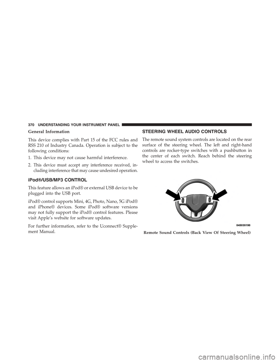
STEERING WHEEL AUDIO CONTROLS
The remote sound system controls are located on the rear
surface of the steering wheel. The left and right-hand
controls are rocker-type switches with a pushbutton in
the center of each switch. Reach behind the steering
wheel to access the switches.
Remote Sound Controls (Back View Of Steering Wheel)
370 UNDERSTANDING YOUR INSTRUMENT PANEL
Page 373 of 648
Right-Hand Switch Functions
•Push the top of the switch to increase the volume.
•Push the bottom of the switch to decrease the volume.
•Push the button in the center of the switch to change
modes (i.e., AM, FM, etc.).
Left-Hand Switch Functions For Radio Operation
•Push the top of the switch to SEEK the next listenable
station up from the current setting.
•Push the bottom of the switch to SEEK the next
listenable station down from the current setting.
•Push the button in the center of the switch to tune to
the next preset that you have programmed.
Left-Hand Switch Functions For Media (i.e., CD)
Operation
•Push the top of the switch once to listen to the next
track.
•Push the bottom of the switch once either to listen to
the beginning of the current track or to listen to the
beginning of the previous track if it is within eight
seconds after the current track begins to play.
•Push the switch up or down twice to listen to the
second track, three times to listen to the third track,
and so forth.
•Push the button located in the center of the switch to
change to the next preset that you have programmed.
4
UNDERSTANDING YOUR INSTRUMENT PANEL 371
Page 374 of 648
CD/DVD DISC MAINTENANCE
To keep a CD/DVD in good condition, take the following
precautions:
1. Handle the disc by its edge; avoid touching the
surface.
2. If the disc is stained, clean the surface with a soft cloth,
wiping from center to edge.
3. Do not apply paper or tape to the disc; avoid scratch-
ing the disc.
4. Do not use solvents such as benzene, thinner, cleaners,
or anti-static sprays.
5. Store the disc in its case after playing.
6. Do not expose the disc to direct sunlight.
7. Do not store the disc where temperatures may become
too high.
NOTE:If you experience difficulty in playing a particular
disc, it may be damaged (e.g., scratched, reflective coat-
ing removed, a hair, moisture or dew on the disc)
oversized, or have protection encoding. Try a known
good disc before considering disc player service.
RADIO OPERATION AND MOBILE PHONES
Under certain conditions, the mobile phone being on in
your vehicle can cause erratic or noisy performance from
your radio. This condition may be lessened or eliminated
by relocating the mobile phone antenna. This condition is
not harmful to the radio. If your radio performance does
not satisfactorily “clear” by the repositioning of the
antenna, it is recommended that the radio volume be
turned down or off during mobile phone operation when
not using Uconnect® (if equipped).
372 UNDERSTANDING YOUR INSTRUMENT PANEL
Page 375 of 648
CLIMATE CONTROLS
The air conditioning and heating system is designed to
make you comfortable in all types of weather. This
system can be operated through either the instrument
panel or through the Uconnect® system display.
When the Uconnect® system is in different modes (Ra-
dio, Player, Settings, More, etc.) the driver and passenger
temperature settings will be indicated at the top of the
display.
Manual Climate Controls With Touchscreen — If
Equipped
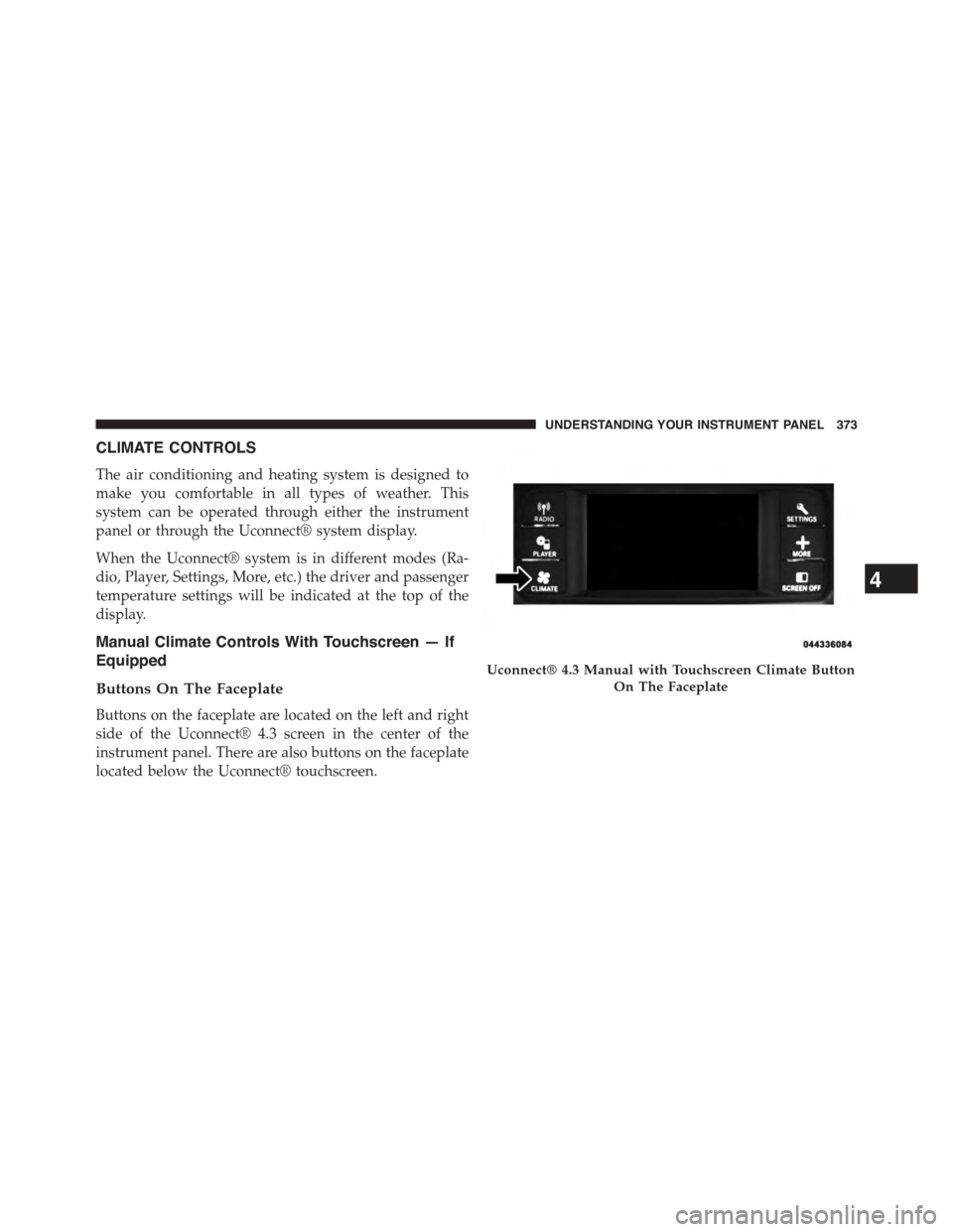
Buttons On The Faceplate
Buttons on the faceplate are located on the left and right
side of the Uconnect® 4.3 screen in the center of the
instrument panel. There are also buttons on the faceplate
located below the Uconnect® touchscreen.
Uconnect® 4.3 Manual with Touchscreen Climate Button
On The Faceplate
4
UNDERSTANDING YOUR INSTRUMENT PANEL 373
Page 376 of 648
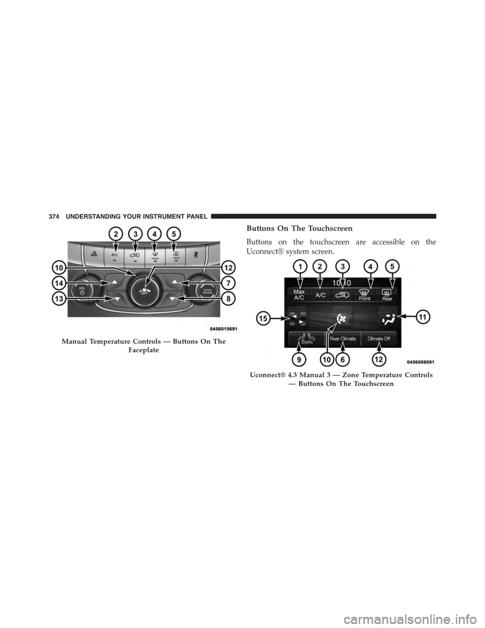
Buttons On The Touchscreen
Buttons on the touchscreen are accessible on the
Uconnect® system screen.
Manual Temperature Controls — Buttons On The
Faceplate
Uconnect® 4.3 Manual 3 — Zone Temperature Controls
— Buttons On The Touchscreen
374 UNDERSTANDING YOUR INSTRUMENT PANEL
Page 377 of 648
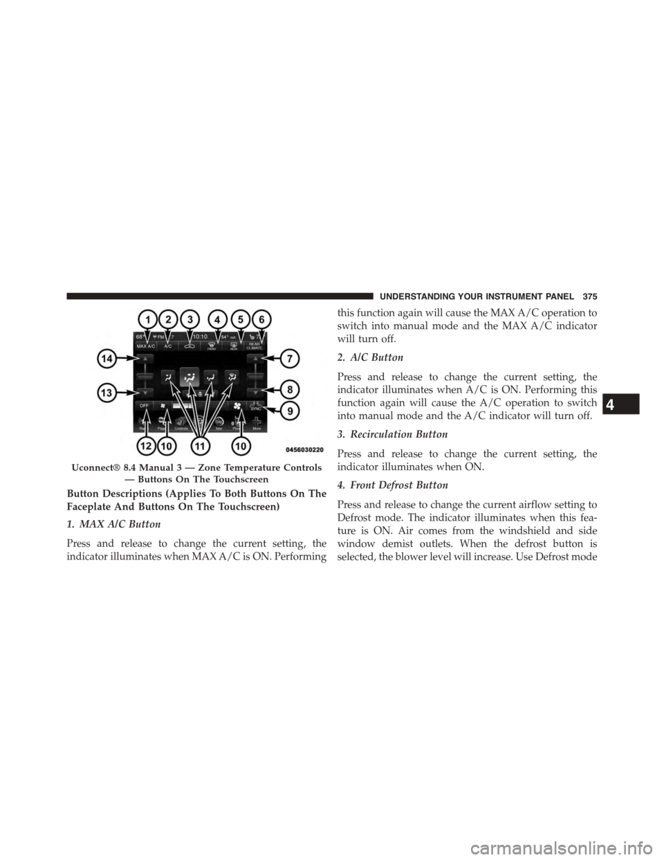
Button Descriptions (Applies To Both Buttons On The
Faceplate And Buttons On The Touchscreen)
1. MAX A/C Button
Press and release to change the current setting, the
indicator illuminates when MAX A/C is ON. Performing
this function again will cause the MAX A/C operation to
switch into manual mode and the MAX A/C indicator
will turn off.
2. A/C Button
Press and release to change the current setting, the
indicator illuminates when A/C is ON. Performing this
function again will cause the A/C operation to switch
into manual mode and the A/C indicator will turn off.
3. Recirculation Button
Press and release to change the current setting, the
indicator illuminates when ON.
4. Front Defrost Button
Press and release to change the current airflow setting to
Defrost mode. The indicator illuminates when this fea-
ture is ON. Air comes from the windshield and side
window demist outlets. When the defrost button is
selected, the blower level will increase. Use Defrost mode
Uconnect® 8.4 Manual 3 — Zone Temperature Controls
— Buttons On The Touchscreen
4
UNDERSTANDING YOUR INSTRUMENT PANEL 375
Page 378 of 648
with maximum temperature settings for best windshield
and side window defrosting and defogging. Performing
this function will cause the ATC to switch into manual
mode. If the front defrost mode is turned off the climate
system will return the previous setting.
5. Rear Defrost Button
Press and release this button to turn on the rear window
defroster and the heated outside mirrors (if equipped).
An indicator will illuminate when the rear window
defroster is on. The rear window defroster automatically
turns off after 10 minutes.
CAUTION!
Failure to follow these cautions can cause damage to
the heating elements:
(Continued)
CAUTION!(Continued)
•Use care when washing the inside of the rear
window. Do not use abrasive window cleaners on
the interior surface of the window. Use a soft cloth
and a mild washing solution, wiping parallel to the
heating elements. Labels can be peeled off after
soaking with warm water.
•Do not use scrapers, sharp instruments, or abrasive
window cleaners on the interior surface of the
window.
•Keep all objects a safe distance from the window.
6. Rear Climate Button — If Equipped
Press and release this button to turn on the rear climate
controls. The indicator will illuminate when the rear
climate controls are ON. Performing this function again
will turn OFF the rear climate controls.
376 UNDERSTANDING YOUR INSTRUMENT PANEL
Page 379 of 648
7. Passenger Temperature Control Up Button
(Uconnect® 8.4 Only)
Provides the passenger with independent temperature
control. Push the button for warmer temperature set-
tings.
NOTE:Pressing this button while in Sync mode will
automatically exit Sync.
8. Passenger Temperature Control Down Button
(Uconnect® 8.4 Only)
Provides the passenger with independent temperature
control. Push the button for cooler temperature settings.
NOTE:Pressing this button while in Sync mode will
automatically exit Sync.
9. SYNC
Press the Sync button on the touchscreen to toggle the
Sync feature On/Off. The Sync indicator is illuminated
when this feature is enabled. Sync is used to synchronize
the passenger temperature setting with the driver tem-
perature setting. Changing the passenger temperature
setting while in Sync will automatically exit this feature.
10. Blower Control
Blower control is used to regulate the amount of air
forced through the climate system. There are seven
blower speeds available. Adjusting the blower will cause
automatic mode to switch to manual operation. The
speeds can be selected using either the blower control
knob or the buttons on the touchscreen as follows:
Blower Control Knob On The Faceplate
The blower speed increases as you turn the blower
control knob clockwise from the lowest blower setting.
The blower speed decreases as you turn the blower
control knob counterclockwise.
4
UNDERSTANDING YOUR INSTRUMENT PANEL 377
Page 380 of 648
Button On The Touchscreen
Use the small blower icon to reduce the blower setting
and the large blower icon to increase the blower setting.
Blower can also be selected by pressing the blower bar
area between the icons.
11. Modes
The airflow distribution mode can be adjusted so air
comes from the instrument panel outlets, floor outlets,
and demist outlets. The Mode settings are as follows:
•Panel Mode
Air comes from the outlets in the instrument
panel. Each of these outlets can be individu-
ally adjusted to direct the flow of air. The air
vanes of the center outlets and outboard outlets can
be moved up and down or side to side to regulate
airflow direction. There is a shut off wheel located
below the air vanes to shut off or adjust the amount
of airflow from these outlets.
•Bi-Level Mode
Air comes from the instrument panel outlets
and floor outlets. A slight amount of air is
directed through the defrost and side window
demister outlets.
NOTE:BI-LEVEL mode is designed under comfort con-
ditions to provide cooler air out of the panel outlets and
warmer air from the floor outlets.
•Floor Mode
Air comes from the floor outlets. A slight
amount of air is directed through the defrost
and side window demister outlets.
•Mix Mode
Air comes from the floor, defrost and side
window demist outlets. This mode works best
in cold or snowy conditions.
378 UNDERSTANDING YOUR INSTRUMENT PANEL