stop start DODGE JOURNEY 2015 1.G Owner's Guide
[x] Cancel search | Manufacturer: DODGE, Model Year: 2015, Model line: JOURNEY, Model: DODGE JOURNEY 2015 1.GPages: 648
Page 435 of 648
WARNING!(Continued)
•Be sure the parking brake is fully disengaged
before driving; failure to do so can lead to brake
failure and a collision.
•Always fully apply the parking brake when leav-
ing your vehicle or it may roll and cause damage or
injury. Also, be certain to leave the transmission in
PARK. Failure to do so may cause the vehicle to roll
and cause damage or injury.
CAUTION!
If the “Brake Warning Light” remains on with the
parking brake released, a brake system malfunction
is indicated. Have the brake system serviced by an
authorized dealer immediately.
BRAKE SYSTEM
Your vehicle is equipped with dual hydraulic
brake systems. If either of the two hydraulic
systems loses normal capability, the remaining
system will still function. However, there will
be some loss of overall braking effectiveness. This will be
evident by increased pedal travel during application and
greater pedal force required to slow or stop the vehicle. In
addition, if the malfunction is caused by a leak in the
hydraulic system, the “Brake Warning Light” will turn on
as the brake fluid level drops in the master cylinder.
In the event power assist is lost for any reason (i.e.,
repeated brake applications with the engine OFF) the
brakes will still function. However, the effort required to
brake the vehicle will be much greater than that required
with the power system operating.
5
STARTING AND OPERATING 433
Page 436 of 648
WARNING!
•Riding the brakes can lead to brake failure and
possibly a collision. Driving with your foot resting
or riding on the brake pedal can result in abnor-
mally high brake temperatures, excessive lining
wear, and possible brake damage. You would not
have your full braking capacity in an emergency.
•Driving a vehicle with the “Brake Warning Light”
on is dangerous. A significant decrease in braking
performance or vehicle stability during braking
may occur. It will take you longer to stop the
vehicle or will make your vehicle harder to control.
You could have a collision. Have the vehicle
checked immediately.
ELECTRONIC BRAKE CONTROL SYSTEM
Your vehicle is equipped with an advanced electronic
brake control system commonly referred to as ESC. This
system includes Anti-Lock Brake System (ABS), Brake
Assist System (BAS), Traction Control System (TCS),
Electronic Roll Mitigation (ERM), Electronic Stability
Control (ESC), Trailer Sway Control (TSC) and Hill Start
Assist (HSA). These systems work together to enhance
both vehicle stability and control in various driving
conditions.
Anti-Lock Brake System (ABS)
The Anti-Lock Brake System (ABS) provides increased
vehicle stability and brake performance under most
braking conditions. The system automatically “pumps”
the brakes during severe braking conditions to prevent
wheel lock-up.
When the vehicle is driven over 7 mph (11 km/h), you
may also hear a slight clicking sound as well as some
434 STARTING AND OPERATING
Page 437 of 648
related motor noises. These noises are the system per-
forming its self check cycle to ensure that the ABS is
working properly. This self check occurs each time the
vehicle is started and accelerated past 7 mph (11 km/h).
ABS is activated during braking under certain road or
stopping conditions. ABS-inducing conditions can in-
clude ice, snow, gravel, bumps, railroad tracks, loose
debris, or panic stops.
You also may experience the following when the brake
system goes into Anti-lock:
•The ABS motor running (it may continue to run for a
short time after the stop),
•The clicking sound of solenoid valves,
•Brake pedal pulsations, and
•A slight drop or fall away of the brake pedal at the end
of the stop.
These are all normal characteristics of ABS.
WARNING!
•The ABS contains sophisticated electronic equip-
ment that may be susceptible to interference
caused by improperly installed or high output
radio transmitting equipment. This interference
can cause possible loss of anti-lock braking capa-
bility. Installation of such equipment should be
performed by qualified professionals.
•Pumping of the Anti-Lock Brakes will diminish
their effectiveness and may lead to an accident.
Pumping makes the stopping distance longer. Just
press firmly on your brake pedal when you need to
slow down or stop.
(Continued)
5
STARTING AND OPERATING 435
Page 439 of 648
If both the Brake System Warning Light and the ABS
Light remain on, the ABS and Electronic Brake Force
Distribution (EBD) systems are not functioning. Immedi-
ate repair to the ABS system is required.
Brake Assist System (BAS)
The BAS is designed to optimize the vehicle’s braking
capability during emergency braking maneuvers. The
system detects an emergency braking situation by sens-
ing the rate and amount of brake application and then
applies optimum pressure to the brakes. This can help
reduce braking distances. The BAS complements the
ABS. Applying the brakes very quickly results in the best
BAS assistance. To receive the benefit of the system, you
must apply continuous braking pressure during the
stopping sequence, (do not “pump” the brakes). Do not
reduce brake pedal pressure unless braking is no longer
desired. Once the brake pedal is released, the BAS is
deactivated.
WARNING!
BAS cannot prevent the natural laws of physics from
acting on the vehicle, nor can it increase the traction
afforded by prevailing road conditions. BAS cannot
prevent accidents, including those resulting from
excessive speed in turns, driving on very slippery
surfaces, or hydroplaning. The capabilities of a BAS-
equipped vehicle must never be exploited in a reck-
less or dangerous manner, which could jeopardize
the user’s safety or the safety of others.
Traction Control System (TCS)
This system monitors the amount of wheel spin of each of
the driven wheels. If wheel spin is detected, brake
pressure is applied to the slipping wheel(s) and engine
power is reduced to provide enhanced acceleration and
stability. A feature of the TCS system, Brake Limited
Differential (BLD), functions similar to a limited slip
5
STARTING AND OPERATING 437
Page 444 of 648
flashes when TCS is active. If the “ESC Activation/
Malfunction Indicator Light” begins to flash during ac-
celeration, ease up on the accelerator and apply as little
throttle as possible. Be sure to adapt your speed and
driving to the prevailing road conditions.
NOTE:
•The “ESC Activation/Malfunction Indicator Light”
and the “ESC OFF Indicator Light” come on momen-
tarily each time the ignition switch is turned ON.
•Each time the ignition is turned ON, the ESC system
will be ON even if it was turned off previously. Except
for when the vehicle is started while in 4WD Low
Range.
•The ESC system will make buzzing or clicking sounds
when it is active. This is normal; the sounds will stop
when ESC becomes inactive following the maneuver
that caused the ESC activation.
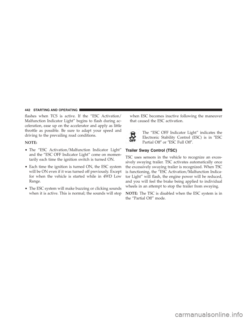
The “ESC OFF Indicator Light” indicates the
Electronic Stability Control (ESC) is in#ESC
Partial Off#or#ESC Full Off#.
Trailer Sway Control (TSC)
TSC uses sensors in the vehicle to recognize an exces-
sively swaying trailer. TSC activates automatically once
the excessively swaying trailer is recognized. When TSC
is functioning, the “ESC Activation/Malfunction Indica-
tor Light” will flash, the engine power will be reduced,
and you will feel the brake being applied to individual
wheels in an attempt to stop the trailer from swaying.
NOTE:The TSC is disabled when the ESC system is in
the “Partial Off” mode.
442 STARTING AND OPERATING
Page 445 of 648
WARNING!
•TSC cannot stop all trailers from swaying. Always
use caution when towing a trailer and follow the
tongue weight recommendations. Refer to ”Vehicle
Loading” and “Trailer Towing” in “Starting and
Operating” for further information.
•If TSC activates while towing a trailer, stop the
vehicle at the nearest safe location and adjust the
trailer load to eliminate the trailer sway.
•Failure to follow these warnings can result in an
accident or serious personal injury.
Hill Start Assist (HSA)
The HSA system is designed to assist the driver when
starting a vehicle from a stop on a hill. HSA will maintain
the level of brake pressure the driver applied for a short
period of time after the driver takes their foot off of the
brake pedal. If the driver does not apply the throttle
during this short period of time, the system will release
brake pressure and the vehicle will roll down the hill. The
system will release brake pressure in proportion to the
amount of throttle applied as the vehicle starts to move in
the intended direction of travel.
HSA Activation Criteria
The following criteria must be met in order for HSA to
activate:
•Vehicle must be stopped.
•Vehicle must be on a 6% (approximate) grade or
greater hill.
•Gear selection matches vehicle uphill direction (i.e.,
vehicle facing uphill is in forward gear; vehicle back-
ing uphill is in REVERSE gear).
5
STARTING AND OPERATING 443
Page 459 of 648
WARNING!
Overloading of your tires is dangerous. Overloading
can cause tire failure, affect vehicle handling, and
increase your stopping distance. Use tires of the
recommended load capacity for your vehicle. Never
overload them.
TIRES — GENERAL INFORMATION
Tire Pressure
Proper tire inflation pressure is essential to the safe and
satisfactory operation of your vehicle. Four primary areas
are affected by improper tire pressure:
•Safety and Vehicle Stability
•Economy
•Tread Wear
•Ride Comfort
Safety
WARNING!
•Improperly inflated tires are dangerous and can
cause collisions.
•Under-inflation increases tire flexing and can re-
sult in over-heating and tire failure.
•Over-inflation reduces a tire’s ability to cushion
shock. Objects on the road and chuckholes can
cause damage that result in tire failure.
•Over-inflated or under-inflated tires can affect ve-
hicle handling and can fail suddenly, resulting in
loss of vehicle control.
•Unequal tire pressures can cause steering prob-
lems. You could lose control of your vehicle.
(Continued)
5
STARTING AND OPERATING 457
Page 466 of 648
your original equipment tire, replace (or repair) the
original equipment tire and reinstall on the vehicle at the
first opportunity.
Limited-Use Spare — If Equipped
The limited-use spare tire is for temporary emergency
use only. This tire is identified by a label located on the
limited-use spare wheel. This label contains the driving
limitations for this spare. This tire may look like the
original equipped tire on the front or rear axle of your
vehicle, but it is not. Installation of this limited-use spare
tire affects vehicle handling. Since it is not the same as
your original equipment tire, replace (or repair) the
original equipment tire and reinstall on the vehicle at the
first opportunity.
WARNING!
Limited-use spares are for emergency use only. In-
stallation of this limited-use spare tire affects vehicle
handling. With this tire, do not drive more than the
speed listed on the limit-use spare wheel. Keep
inflated to the cold tire inflation pressures listed on
your Tire and Loading Information Placard located
on the driver ’s side B-Pillar or the rear edge of the
driver ’s side door. Replace (or repair) the original
equipment tire at the first opportunity and reinstall it
on your vehicle. Failure to do so could result in loss
of vehicle control.
Tire Spinning
When stuck in mud, sand, snow, or ice conditions, do not
spin your vehicle’s wheels above 30 mph (48 km/h) or
for longer than 30 seconds continuously without stop-
ping.
464 STARTING AND OPERATING
Page 471 of 648
CAUTION!
To avoid damage to your vehicle or tires, observe the
following precautions:
•Because of restricted traction device clearance be-
tween tires and other suspension components, it is
important that only traction devices in good condi-
tion are used. Broken devices can cause serious
damage. Stop the vehicle immediately if noise
occurs that could indicate device breakage. Remove
the damaged parts of the device before further use.
•Install device as tightly as possible and then re-
tighten after driving about½mile (0.8 km).
•Do not exceed 30 mph (48 km/h).
•Drive cautiously and avoid severe turns and large
bumps, especially with a loaded vehicle.
•Do not drive for a prolonged period on dry pave-
ment.
(Continued)
CAUTION!(Continued)
•Observe the traction device manufacturer ’s instruc-
tions on the method of installation, operating
speed, and conditions for use. Always use the
suggested operating speed of the device manufac-
turer ’s if it is less than 30 mph (48 km/h).
•Do not use traction devices on a compact spare tire.
TIRE ROTATION RECOMMENDATIONS
The tires on the front and rear of your vehicle operate at
different loads and perform different steering, driving,
and braking functions. For these reasons, they wear at
unequal rates.
These effects can be reduced by timely rotation of tires.
The benefits of rotation are especially worthwhile with
aggressive tread designs such as those on all season type
5
STARTING AND OPERATING 469
Page 475 of 648
CAUTION!(Continued)
•After inspecting or adjusting the tire pressure,
always reinstall the valve stem cap. This will
prevent moisture and dirt from entering the valve
stem, which could damage the Tire Pressure Moni-
toring Sensor.
NOTE:
•The TPMS is not intended to replace normal tire care
and maintenance, or to provide warning of a tire
failure or condition.
•The TPMS should not be used as a tire pressure gauge
while adjusting your tire pressure.
•Driving on a significantly under-inflated tire causes
the tire to overheat and can lead to tire failure.
Under-inflation also reduces fuel efficiency and tire
tread life, and may affect the vehicle’s handling and
stopping ability.
•The TPMS is not a substitute for proper tire mainte-
nance, and it is the driver ’s responsibility to maintain
correct tire pressure using an accurate tire pressure
gauge, even if under-inflation has not reached the level
to trigger illumination of the “Tire Pressure Monitor-
ing Telltale Light.”
•Seasonal temperature changes will affect tire pressure,
and the TPMS will monitor the actual tire pressure in
the tire.
Base System
The Tire Pressure Monitor System (TPMS) uses wireless
technology with wheel rim mounted electronic sensors to
5
STARTING AND OPERATING 473