ECU DODGE JOURNEY 2015 1.G Owner's Manual
[x] Cancel search | Manufacturer: DODGE, Model Year: 2015, Model line: JOURNEY, Model: DODGE JOURNEY 2015 1.GPages: 140, PDF Size: 23.09 MB
Page 46 of 140
POWER SUNROOF
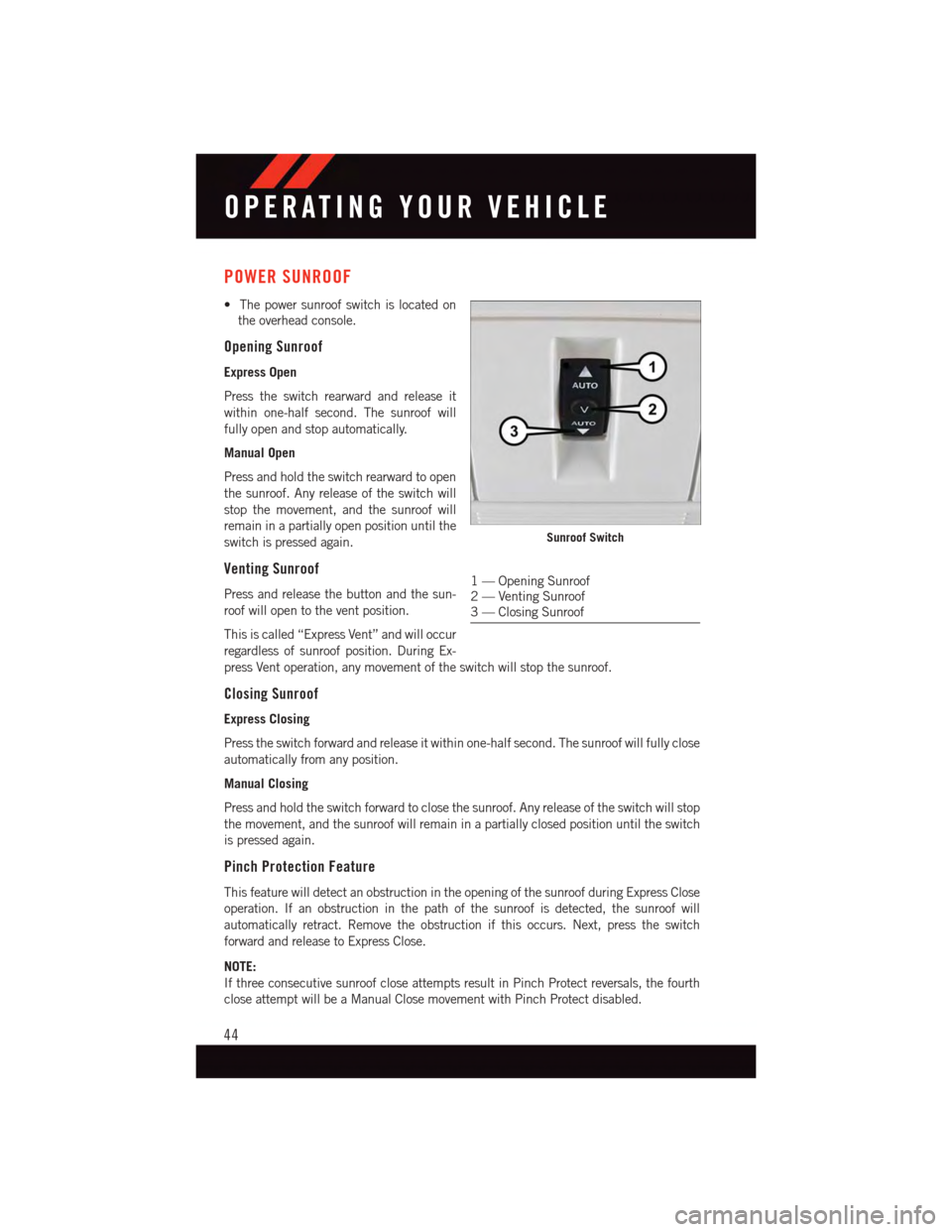
•Thepowersunroofswitchislocatedon
the overhead console.
Opening Sunroof
Express Open
Press the switch rearward and release it
within one-half second. The sunroof will
fully open and stop automatically.
Manual Open
Press and hold the switch rearward to open
the sunroof. Any release of the switch will
stop the movement, and the sunroof will
remain in a partially open position until the
switch is pressed again.
Venting Sunroof
Press and release the button and the sun-
roof will open to the vent position.
This is called “Express Vent” and will occur
regardless of sunroof position. During Ex-
press Vent operation, any movement of the switch will stop the sunroof.
Closing Sunroof
Express Closing
Press the switch forward and release it within one-half second. The sunroof will fully close
automatically from any position.
Manual Closing
Press and hold the switch forward to close the sunroof. Any release of the switch will stop
the movement, and the sunroof will remain in a partially closed position until the switch
is pressed again.
Pinch Protection Feature
This feature will detect an obstruction in the opening of the sunroof during Express Close
operation. If an obstruction in the path of the sunroof is detected, the sunroof will
automatically retract. Remove the obstruction if this occurs. Next, press the switch
forward and release to Express Close.
NOTE:
If three consecutive sunroof close attempts result in Pinch Protect reversals, the fourth
close attempt will be a Manual Close movement with Pinch Protect disabled.
Sunroof Switch
1—OpeningSunroof2—VentingSunroof3—ClosingSunroof
OPERATING YOUR VEHICLE
44
Page 47 of 140
WARNING!
•Donotletchildrenplaywiththesunroof.Neverleavechildrenunattendedina
vehicle, or with access to an unlocked vehicle. Do not leave the Key Fob in or near
the vehicle, and do not leave the ignition of a vehicle equipped with Keyless
Enter-N-Go™ in the ACC or ON/RUN mode. Occupants, particularly unattended
children, can become entrapped by the power sunroof while operating the power
sunroof switch. Such entrapment may result in serious injury or death.
•Inacollision,thereisagreaterriskofbeingthrownfromavehiclewithanopen
sunroof. You could also be severely injured or killed. Always fasten your seat belt
properly and make sure all passengers are properly secured.
•Do not allow small children to operate the sunroof. Never allow your fingers, other body
parts, or any object to project through the sunroof opening. Injury may result.
WIND BUFFETING
Wind buffeting can be described as a helicopter-type percussion sound. If buffeting
occurs with the rear windows open, adjust the front and rear windows together.
If buffeting occurs with the sunroof open, adjust the sunroof opening, or adjust any
window. This will minimize buffeting.
OPERATING YOUR VEHICLE
45
Page 57 of 140
Direct Tune
•Tunedirectlytoaradiostationbypressingthe“Tune”buttononthescreen,and
entering the desired station number.
Store Radio Presets
•Yourradiocanstore12totalpresetstations.Theyareshownatthetopofyourscreen.
To s e e a l l 1 2 s t a t i o n s , P r e s s t h e “ A l l ” b u t t o n o n t h e t o u c h s c r e e n ( 4 . 3 & 4 . 3 S ) o r p r e s s
the “arrow” button on the touchscreen at the top right of the screen to toggle between
the six presets (8.4 & 8.4N).
•Tosetastationintomemorypressandholdthedesirednumberedbuttononthe
touchscreen for more than two seconds or until you hear a confirmation beep.
SiriusXM SATELLITE RADIO
•SiriusXMSatelliteRadiogivesyouover130channels,including100%commercial-
free music from nearly every genre, plus all your favorite sports, news, talk and
entertainment channels – all with crystal clear, coast-to-coast coverage, all in one place
and all at your fingertips.
•ToaccessSiriusXMSatelliteRadio,pressthe“Radioband”buttononthetouchscreen
and select the “SAT” button on the touchscreen (4.3S) or press the “SAT” button on
the touchscreen on the main Radio screen (8.4 & 8.4N).
•ThefollowingdescribesfeaturesthatareavailablewheninSiriusXMSatelliteRadio
mode.
•Unlessotherwisenoted,theinformationprovidedontheoperationandfunctionalityof
the radios in this section is common to all Uconnect®radios.
Selecting SiriusXM Satellite Channels
Seek Up/Seek Down
•Pressthe“Seekarrow”buttonsonthetouchscreenforlessthantwosecondstoseek
through channels in SAT mode.
•Pressandholdeither“arrow”buttononthetouchscreenformorethantwosecondsto
bypass channels without stopping. The radio will stop at the next listenable channel
once the arrow button on the touchscreen is released.
Direct Tune
•TunedirectlytoaSATchannelbypressingthe“Tune”buttononthescreen,and
entering the desired station number.
Info (4.3S Only)
•ProvidesdetailedinformationaboutthecurrentSiriusXMSatelliteRadiochannel.
More... (4.3S Only)
•Accessmoremenus:Audio,Favorites,GameZone,andReplay.
ELECTRONICS
55
Page 59 of 140
Replay
•Letsyoureplayupto44minutesofthecontentofthecurrentSiriusXMSatelliteRadio
channel.
ReplayOptionOption Description
Play/Pause Press to Pause content playback. Press “Pause/Play” again to resumeplayback.
Rewind/RW Rewinds the channel content in steps of five seconds. Press and hold torewind continuously, then release to begin playing content at that point.
FastForward/FWForwards the content, and works similarly to Rewind/RW. However, FastForward/FW can only be used when content has been previously rewound.
Replay Time Displays the amount of time in the upper center of the screen by which yourcontent lags the Live channel.
Live Resumes playback of Live content at any time while replaying rewoundcontent.
iPod®/CD/AUX CONTROLS
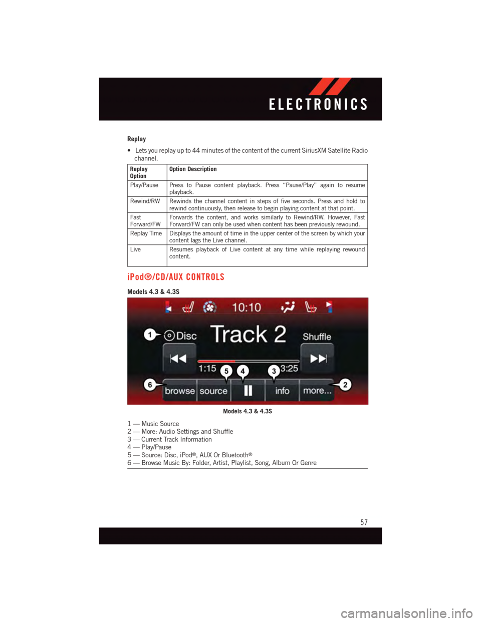
Models 4.3 & 4.3S
Models 4.3 & 4.3S
1—MusicSource2—More:AudioSettingsandShuffle3—CurrentTrackInformation4—Play/Pause5—Source:Disc,iPod®,AUXOrBluetooth®
6—BrowseMusicBy:Folder,Artist,Playlist,Song,AlbumOrGenre
ELECTRONICS
57
Page 80 of 140
Uconnect® 8.4 Customer Programmable Features
•TheUconnect®8.4 system allows you to access Customer Programmable feature
settings such as Display, Clock, Safety/Assistance, Lights, Doors & Locks, Heated
Seats, Engine Off Operation, Compass Settings, Audio, Phone/Bluetooth®and SIRIUS
Setup through buttons on the touchscreen.
•Pressthe“More”buttononthebottomofthetouchscreen,thenpressthe“Settings”
button on the faceplate to access the Settings screen. When making a selection, scroll
up or down until the preferred setting is highlighted, then press and release the
preferred setting until a check-mark appears next to the setting, showing that setting
has been selected. The following feature settings are available:
•Display•AutoOnComfort&RemoteStart
•Clock•EngineOffOptions
•Safety/Assistance•Audio
•Lights•Phone/Bluetooth®
•Doors&Locks•SIRIUSSetup
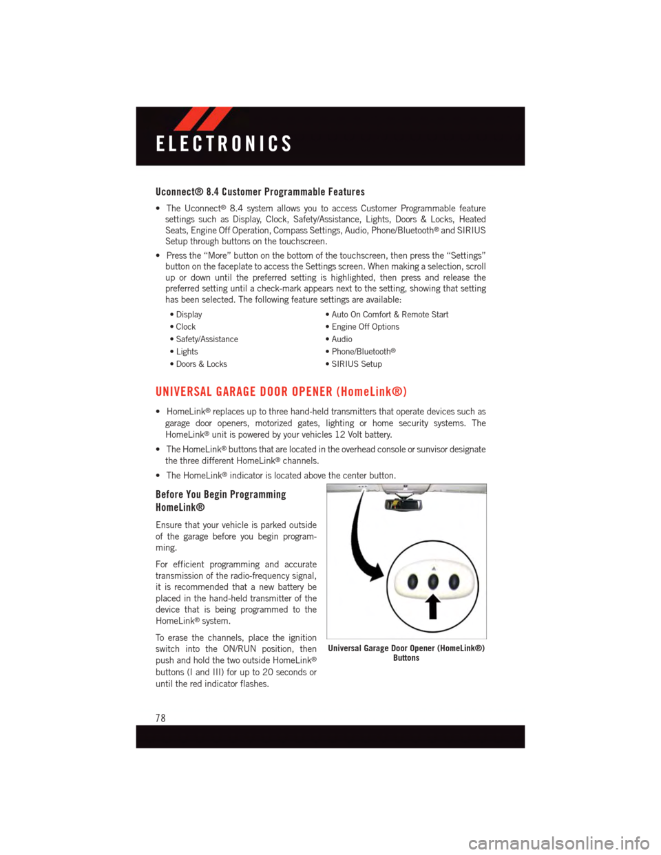
UNIVERSAL GARAGE DOOR OPENER (HomeLink®)
•HomeLink®replaces up to three hand-held transmitters that operate devices such as
garage door openers, motorized gates, lighting or home security systems. The
HomeLink®unit is powered by your vehicles 12 Volt battery.
•TheHomeLink®buttons that are located in the overhead console or sunvisor designate
the three different HomeLink®channels.
•TheHomeLink®indicator is located above the center button.
Before You Begin Programming
HomeLink®
Ensure that your vehicle is parked outside
of the garage before you begin program-
ming.
For efficient programming and accurate
transmission of the radio-frequency signal,
it is recommended that a new battery be
placed in the hand-held transmitter of the
device that is being programmed to the
HomeLink®system.
To e r a s e t h e c h a n n e l s , p l a c e t h e i g n i t i o n
switch into the ON/RUN position, then
push and hold the two outside HomeLink®
buttons (I and III) for up to 20 seconds or
until the red indicator flashes.
Universal Garage Door Opener (HomeLink®)Buttons
ELECTRONICS
78
Page 82 of 140
Programming A Non-Rolling Code
NOTE:
For programming Garage Door Openers manufactured before 1995.
1. Turn the ignition switch to the ON/RUN position.
2. Place the hand-held transmitter 1 to 3 inches (3 to 8 cm) away from the HomeLink®
button you wish to program while keeping the HomeLink®indicator light in view.
3. Push and hold the HomeLink®button you want to program while you push and hold
the hand-held transmitter button.
4. Continue to hold both buttons and observe the indicator light. The HomeLink®
indicator will flash slowly and then rapidly after HomeLink®has received the fre-
quency signal from the hand-held transmitter. Release both buttons after the indicator
light changes from slow to rapid.
5. Push and hold the programmed HomeLink®button and observe the indicator light. If
the indicator light stays on constantly, programming is complete and the garage door
(or device) should activate when the HomeLink®button is pushed.
6. To program the two remaining HomeLink®buttons, repeat each step for each
remaining button. DO NOT erase the channels.
Using HomeLink®
To o p e r a t e , p u s h a n d r e l e a s e t h e p r o g r a m m e d H o m e L i n k®button. Activation will now
occur for the programmed device (e.g., garage door opener, gate operator, security system,
entry door lock, home/office lighting, etc.,). The hand-held transmitter of the device may
also be used at any time.
WARNING!
•Yourmotorizeddoororgatewillopenandclosewhileyouareprogrammingthe
universal transceiver. Do not program the transceiver if people or pets are in the
path of the door or gate.
•Donotrunyourvehicleinaclosedgarageorconfinedareawhileprogrammingthe
transceiver. Exhaust gas from your vehicle contains Carbon Monoxide (CO) which is
odorless and colorless. Carbon Monoxide is poisonous when inhaled and can cause
you and others to be severely injured or killed.
ELECTRONICS
80
Page 87 of 140
RECREATIONAL TOWING (BEHIND MOTORHOME, ETC.)
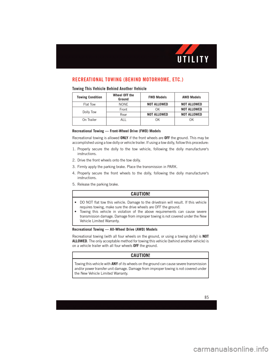
Towing This Vehicle Behind Another Vehicle
Towing ConditionWheel OFF theGroundFWD Models AWD Models
Flat TowNONENOT ALLOWED NOT ALLOWED
Dolly TowFrontOKNOT ALLOWED
RearNOT ALLOWED NOT ALLOWED
On TrailerALLOKOK
Recreational Towing — Front-Wheel Drive (FWD) Models
Recreational towing is allowedONLYif the front wheels areOFFthe ground. This may be
accomplished using a tow dolly or vehicle trailer. If using a tow dolly, follow this procedure:
1. Properly secure the dolly to the tow vehicle, following the dolly manufacturer's
instructions.
2. Drive the front wheels onto the tow dolly.
3. Firmly apply the parking brake. Place the transmission in PARK.
4. Properly secure the front wheels to the dolly, following the dolly manufacturer's
instructions.
5. Release the parking brake.
CAUTION!
•DONOTflattowthisvehicle.Damagetothedrivetrainwillresult.Ifthisvehicle
requires towing, make sure the drive wheels are OFF the ground.
•Towingthisvehicleinviolationoftheaboverequirementscancausesevere
transmission damage. Damage from improper towing is not covered under the New
Vehicle Limited Warranty.
Recreational Towing — All-Wheel Drive (AWD) Models
Recreational towing (with all four wheels on the ground, or using a towing dolly) isNOT
ALLOWED.Theonlyacceptablemethodfortowingthisvehicle(behindanothervehicle)is
on a vehicle trailer with all four wheelsOFFthe ground.
CAUTION!
To w i n g t h i s v e h i c l e w i t hANYof its wheels on the ground can cause severe transmission
and/or power transfer unit damage. Damage from improper towing is not covered under
the New Vehicle Limited Warranty.
UTILITY
85
Page 93 of 140
INSTRUMENT CLUSTER INDICATOR LIGHTS
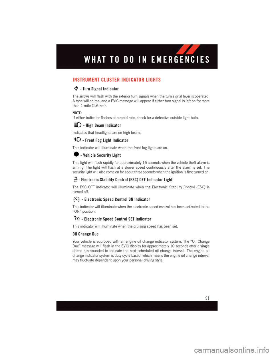
-TurnSignalIndicator
The arrows will flash with the exterior turn signals when the turn signal lever is operated.
Atonewillchime,andaEVICmessagewillappearifeitherturnsignalisleftonformore
than 1 mile (1.6 km).
NOTE:
If either indicator flashes at a rapid rate, check for a defective outside light bulb.
-HighBeamIndicator
Indicates that headlights are on high beam.
-FrontFogLightIndicator
This indicator will illuminate when the front fog lights are on.
-VehicleSecurityLight
This light will flash rapidly for approximately 15 seconds when the vehicle theft alarm is
arming. The light will flash at a slower speed continuously after the alarm is set. The
security light will also come on for about three seconds when the ignition is first turned on.
-ElectronicStabilityControl(ESC)OFFIndicatorLight
The ESC OFF indicator will illuminate when the Electronic Stability Control (ESC) is
turned off.
-ElectronicSpeedControlONIndicator
This indicator will illuminate when the electronic speed control has been activated to the
“ON” position.
-ElectronicSpeedControlSETIndicator
This indicator will illuminate when the cruising speed has been set.
Oil Change Due
Yo u r v e h i c l e i s e q u i p p e d w i t h a n e n g i n e o i l c h a n g e i n d i c a t o r s y s t e m . T h e “ O i l C h a n g e
Due” message will flash in the EVIC display for approximately 10 seconds after a single
chime has sounded to indicate the next scheduled oil change interval. The engine oil
change indicator system is duty cycle based, which means the engine oil change interval
may fluctuate dependent upon your personal driving style.
WHAT TO DO IN EMERGENCIES
91
Page 97 of 140
Spare Tire Removal
NOTE:
On seven-passenger models, fold the third-row passenger seats flat. This will provide more
space when accessing the jacking tools and when operating the winch mechanism.
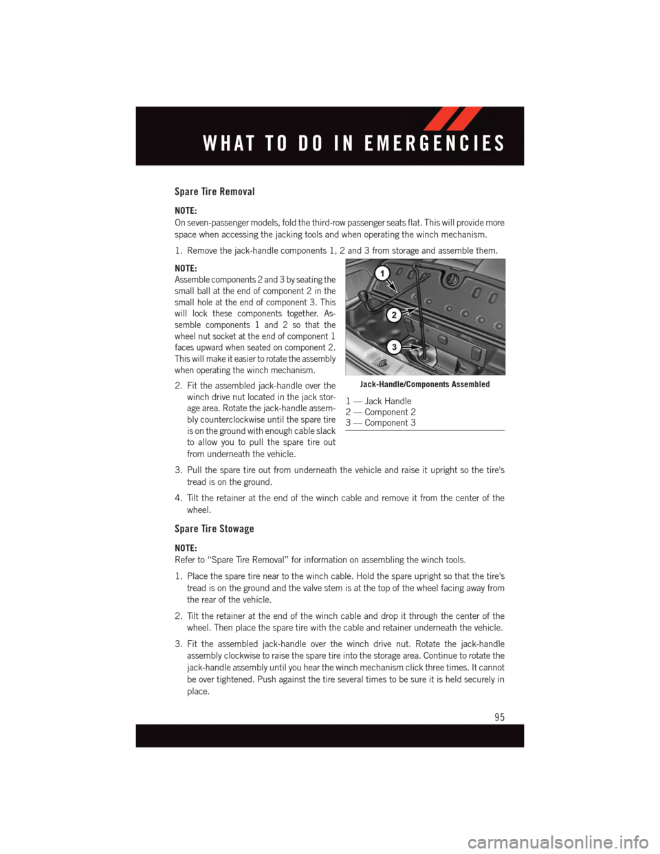
1. Remove the jack-handle components 1, 2 and 3 from storage and assemble them.
NOTE:
Assemble components 2 and 3 by seating the
small ball at the end of component 2 in the
small hole at the end of component 3. This
will lock these components together. As-
semble components 1 and 2 so that the
wheel nut socket at the end of component 1
faces upward when seated on component 2.
This will make it easier to rotate the assembly
when operating the winch mechanism.
2. Fit the assembled jack-handle over the
winch drive nut located in the jack stor-
age area. Rotate the jack-handle assem-
bly counterclockwise until the spare tire
is on the ground with enough cable slack
to allow you to pull the spare tire out
from underneath the vehicle.
3. Pull the spare tire out from underneath the vehicle and raise it upright so the tire's
tread is on the ground.
4. Tilt the retainer at the end of the winch cable and remove it from the center of the
wheel.
Spare Tire Stowage
NOTE:
Refer to “Spare Tire Removal” for information on assembling the winch tools.
1. Place the spare tire near to the winch cable. Hold the spare upright so that the tire's
tread is on the ground and the valve stem is at the top of the wheel facing away from
the rear of the vehicle.
2. Tilt the retainer at the end of the winch cable and drop it through the center of the
wheel. Then place the spare tire with the cable and retainer underneath the vehicle.
3. Fit the assembled jack-handle over the winch drive nut. Rotate the jack-handle
assembly clockwise to raise the spare tire into the storage area. Continue to rotate the
jack-handle assembly until you hear the winch mechanism click three times. It cannot
be over tightened. Push against the tire several times to be sure it is held securely in
place.
Jack-Handle/Components Assembled
1—JackHandle2—Component23—Component3
WHAT TO DO IN EMERGENCIES
95
Page 102 of 140
WARNING!
•Donotattempttochangeatireonthesideofthevehicleclosetomovingtraffic.
Pull far enough off the road to avoid the danger of being hit when operating the jack
or changing the wheel.
•Beingunderajacked-upvehicleisdangerous.Thevehiclecouldslipoffthejack
and fall on you. You could be crushed. Never put any part of your body under a
vehicle that is on a jack. If you need to get under a raised vehicle, take it to an
authorized service center where it can be raised on a lift.
•Neverstartorruntheenginewhilethevehicleisonajack.
•Thejackisdesignedtobeusedasatoolforchangingtiresonly.Thejackshouldnot
be used to lift the vehicle for service purposes. The vehicle should be jacked on a
firm level surface only. Avoid ice or slippery areas.
•Carefullyfollowthesetirechangingwarningstohelppreventpersonalinjuryor
damage to your vehicle:
•Alwaysparkonafirm,levelsurfaceasfarfromtheedgeoftheroadwayaspossible
before raising the vehicle.
•TurnontheHazardWarningflasher.
•Blockthewheeldiagonallyoppositethewheeltoberaised.
•SettheparkingbrakefirmlyandsetanautomatictransmissioninPARK.
•Donotletanyonesitinthevehiclewhenitisonajack.
•Donotgetunderthevehiclewhenitisonajack.
•Onlyusethejackinthepositionsindicatedandforliftingthisvehicleduringatire
change.
•Ifworkingonorneararoadway,beextremelycarefulofmotortraffic.
•Toassurethatsparetires,flatorinflated,aresecurelystowed,sparesmustbe
stowed with the valve stem facing the ground.
•Raisingthevehiclehigherthannecessarycanmakethevehiclelessstable.Itcould
slip off the jack and hurt someone near it. Raise the vehicle only enough to remove
the tire.
•Toavoidpossiblepersonalinjury,handlethewheelcoverswithcaretoavoidcontact
with any sharp edges.
•Toavoidtheriskofforcingthevehicleoffthejack,donottightenthewheelnuts
fully until the vehicle has been lowered. Failure to follow this warning may result in
personal injury.
•Aloosetireorjack,thrownforwardinacollisionorhardstopcouldendangerthe
occupants of the vehicle. Always stow the jack parts and the spare tire in the places
provided. Have the deflated (flat) tire repaired or replaced immediately.
WHAT TO DO IN EMERGENCIES
100