light DODGE JOURNEY 2015 1.G Owner's Manual
[x] Cancel search | Manufacturer: DODGE, Model Year: 2015, Model line: JOURNEY, Model: DODGE JOURNEY 2015 1.GPages: 140, PDF Size: 23.09 MB
Page 39 of 140
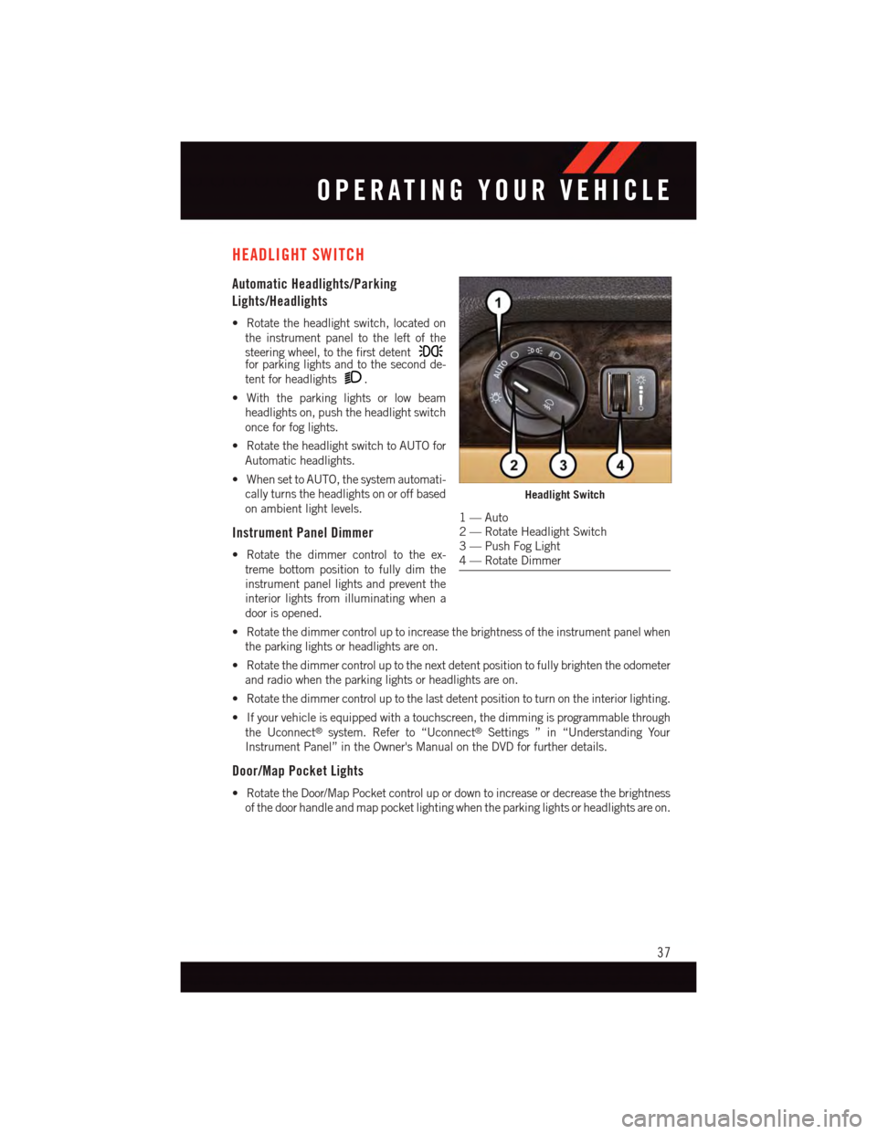
HEADLIGHT SWITCH
Automatic Headlights/Parking
Lights/Headlights
•Rotatetheheadlightswitch,locatedon
the instrument panel to the left of the
steering wheel, to the first detentfor parking lights and to the second de-
tent for headlights.
•Withtheparkinglightsorlowbeam
headlights on, push the headlight switch
once for fog lights.
•RotatetheheadlightswitchtoAUTOfor
Automatic headlights.
•WhensettoAUTO,thesystemautomati-
cally turns the headlights on or off based
on ambient light levels.
Instrument Panel Dimmer
•Rotatethedimmercontroltotheex-
treme bottom position to fully dim the
instrument panel lights and prevent the
interior lights from illuminating when a
door is opened.
•Rotatethedimmercontroluptoincreasethebrightnessoftheinstrumentpanelwhen
the parking lights or headlights are on.
•Rotatethedimmercontroluptothenextdetentpositiontofullybrightentheodometer
and radio when the parking lights or headlights are on.
•Rotatethedimmercontroluptothelastdetentpositiontoturnontheinteriorlighting.
•Ifyourvehicleisequippedwithatouchscreen,thedimmingisprogrammablethrough
the Uconnect®system. Refer to “Uconnect®Settings ” in “Understanding Your
Instrument Panel” in the Owner's Manual on the DVD for further details.
Door/Map Pocket Lights
•RotatetheDoor/MapPocketcontrolupordowntoincreaseordecreasethebrightness
of the door handle and map pocket lighting when the parking lights or headlights are on.
Headlight Switch
1—Auto2—RotateHeadlightSwitch3—PushFogLight4—RotateDimmer
OPERATING YOUR VEHICLE
37
Page 45 of 140
Air Recirculation
•UserecirculationformaximumA/Coperation.
•Forwindowdefogging,turntherecirculationbuttonoff.
•IftheRecirculationbuttononthefaceplateispushedwhileintheAUTOmode,the
indicator light may flash three times to indicate the cabin air is being controlled
automatically. The “Recirculation” button on the touchscreen will be greyed out in
these conditions.
Heated Mirrors
The mirrors are heated to melt frost or ice. This feature is activated whenever you turn on
the rear window defroster.
PARKVIEW® REAR BACK-UP CAMERA
Yo u c a n s e e a n o n - s c r e e n i m a g e o f t h e r e a r o f y o u r v e h i c l e w h e n e v e r t h e s h i f t l e v e r i s p u t
into REVERSE. The ParkView®Rear Back-Up Camera image will be displayed on the radio
display screen, located on the center stack of the instrument panel.
If the radio display screen appears foggy, clean the camera lens located on the liftgate.
Refer to your Owner's Manual on the DVD for further details.
WARNING!
Drivers must be careful when backing up; even when using the ParkView®Rear
Back-Up Camera. Always check carefully behind your vehicle, and be sure to check for
pedestrians, animals, other vehicles, obstructions, or blind spots before backing up.
Yo u m u s t c o n t i n u e t o p a y a t t e n t i o n w h i l e b a c k i n g u p . F a i l u r e t o d o s o c a n r e s u l t i n
serious injury or death.
OPERATING YOUR VEHICLE
43
Page 77 of 140
WARNING!
Any voice commanded system should be used only in safe driving conditions following
applicable laws regarding phone use. Your attention should be focused on safely
operating the vehicle. Failure to do so may result in a collision causing you and others
to be severely injured or killed.
VIDEO ENTERTAINMENT SYSTEM (VES™)
System Operation
•Thescreenislocatedontheheadlinerbehindthefrontseat.Tolowerthescreen,press
the release button located in the rear of the overhead console.
•Thesystemmaybecontrolledbythefrontseatoccupantsusingthetouchscreenradio,
or by the rear seat occupants using the remote control.
•Thevideoscreendisplaysinformationinasplit-screenformat.Theleftsideofthe
screen is referred to as Channel 1 and the right side of the screen is referred to as
Channel 2. All modes except video modes are displayed in a split-screen format.
•Tousetheheadphones,pressthepowerbuttonlocatedontherightearcup.Selectthe
channel on the headphones (1 or 2) that corresponds to the channel selected on the
VES™ screen.
Operation Of The Remote
The remote control operates similarly to any DVD remote you have used before and allows
the rear seat passengers to change stations, tracks, discs and audio/video modes and is
designed to control either channel by using the selector switch located on the right side of
the remote.
•Selectanaudiochannel(Rear1fordriver'ssiderearscreenandRear2forpassenger's
side rear screen), then press the “source” button and using the up and down arrows,
highlight disc from the menu and press the “OK” button.
•Pressthepopup/menubuttontonavigatethediscmenuandoptions.
Pressing the MODE button causes the Mode Selection menu to appear on the VES™
screen. Use the remote control arrow buttons to scroll through the available modes, then
press ENTER to select the desired mode.
Pressing the power button will turn the VES™ system ON/OFF.
Auxiliary Audio/Video Input Jacks
•TheAuxjacksarelocatedontherearofthecenterconsole.
•ConnectthevideogameorotherexternalmediadevicestotheAUXjacksfollowingthe
color coding for VES™ jacks.
•Usingeitherthetouchscreenradioorremotecontrol,selectAUXfromtheRearVES™
Control or Mode Selection screen.
•Refertoyourvehicle'sOwnersManualontheDVDforfurtherdetails.
ELECTRONICS
75
Page 79 of 140
Compass Calibration
This compass is self-calibrating, which eliminates the need to set the compass manually.
When the vehicle is new, the compass may appear erratic and the EVIC will display “CAL”
until the compass is calibrated.
Yo u m a y a l s o c a l i b r a t e t h e c o m p a s s b y c o m p l e t i n g o n e o r m o r e 3 6 0 d e g r e e t u r n s ( i n a n
area free from large metal or metallic objects) until the “CAL” message displayed in the
EVIC turns off. The compass will now function normally.
PROGRAMMABLE FEATURES
Electronic Vehicle Information Center (EVIC) — If Equipped
•TheEVICcanbeusedtovieworchangethefollowingsettings.PushtheUPor
DOWNbutton until System Setup displays, then push the SELECTbutton.
Scroll through the settings using the UP or DOWN buttons. Push the SELECT
button to change the setting. Push the BACK button to scroll back to a previous menu
or sub menu.
•Fuel Economy•Average Fuel Economy•DistanceToEmpty(DTE)•MilesPerGallon(MPG)
•Tr i p I n f o•Tr i p A•TripB•ElapsedTime
•Vehicle Speed•Ti r e P S I
•Messages•VehicleInfo(CustomerInformation
Features)
Uconnect® 4.3 Customer Programmable Features
•TheUconnect®4.3 system allows you to access Customer Programmable feature
settings such as Display, Clock, Safety/Assistance, Lights, Doors & Locks, Heated
Seats, Engine Off Operation, Compass Settings, Audio, Phone/ Bluetooth®and SIRIUS
Setup through buttons on the faceplate and buttons on the touchscreen.
•Pressthe“Settings”buttonontherightsideoftheunittoaccesstheSettingsscreen,
use the “Page Up/Down” buttons on the touchscreen to scroll through the following
settings. The following feature settings are available:
•Display•AutoOnComfort&RemoteStart
•Clock•EngineOffOptions
•Safety/Assistance•Audio
•Lights•Phone/Bluetooth®
•Doors&Locks•SIRIUSSetup
ELECTRONICS
77
Page 80 of 140
Uconnect® 8.4 Customer Programmable Features
•TheUconnect®8.4 system allows you to access Customer Programmable feature
settings such as Display, Clock, Safety/Assistance, Lights, Doors & Locks, Heated
Seats, Engine Off Operation, Compass Settings, Audio, Phone/Bluetooth®and SIRIUS
Setup through buttons on the touchscreen.
•Pressthe“More”buttononthebottomofthetouchscreen,thenpressthe“Settings”
button on the faceplate to access the Settings screen. When making a selection, scroll
up or down until the preferred setting is highlighted, then press and release the
preferred setting until a check-mark appears next to the setting, showing that setting
has been selected. The following feature settings are available:
•Display•AutoOnComfort&RemoteStart
•Clock•EngineOffOptions
•Safety/Assistance•Audio
•Lights•Phone/Bluetooth®
•Doors&Locks•SIRIUSSetup
UNIVERSAL GARAGE DOOR OPENER (HomeLink®)
•HomeLink®replaces up to three hand-held transmitters that operate devices such as
garage door openers, motorized gates, lighting or home security systems. The
HomeLink®unit is powered by your vehicles 12 Volt battery.
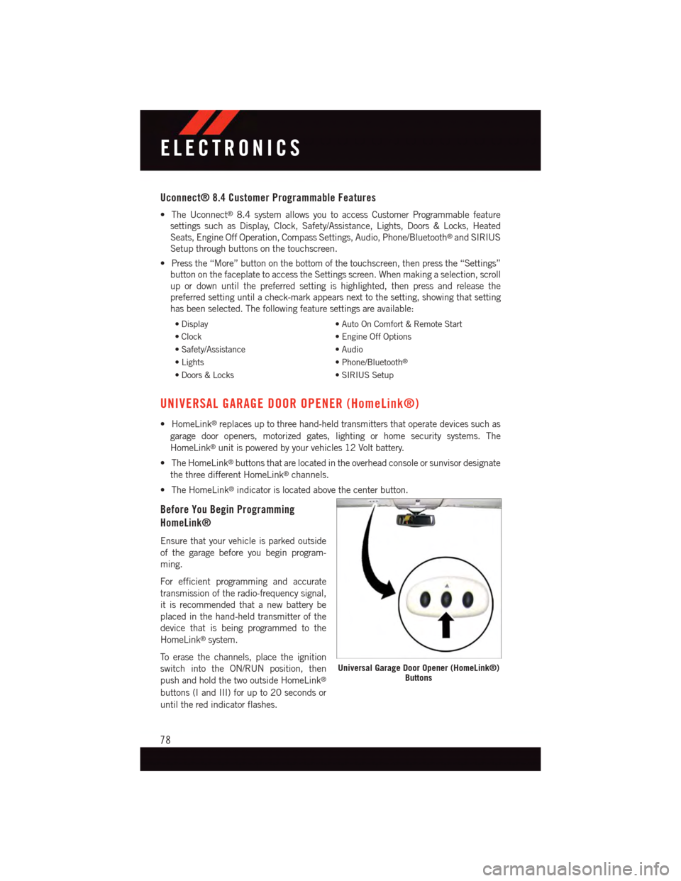
•TheHomeLink®buttons that are located in the overhead console or sunvisor designate
the three different HomeLink®channels.
•TheHomeLink®indicator is located above the center button.
Before You Begin Programming
HomeLink®
Ensure that your vehicle is parked outside
of the garage before you begin program-
ming.
For efficient programming and accurate
transmission of the radio-frequency signal,
it is recommended that a new battery be
placed in the hand-held transmitter of the
device that is being programmed to the
HomeLink®system.
To e r a s e t h e c h a n n e l s , p l a c e t h e i g n i t i o n
switch into the ON/RUN position, then
push and hold the two outside HomeLink®
buttons (I and III) for up to 20 seconds or
until the red indicator flashes.
Universal Garage Door Opener (HomeLink®)Buttons
ELECTRONICS
78
Page 81 of 140
NOTE:
Erasing all channels should only be performed when programming HomeLink®for the first
time. Do not erase channels when programming additional buttons.
If you have any problems, or require assistance, please call toll-free 1-800-355-3515 or,
on the Internet at for information or assistance.
Programming A Rolling Code
NOTE:
For programming Garage Door Openers that were manufactured after 1995. These Garage
Door Openers can be identified by the “LEARN” or “TRAIN” button located where the
hanging antenna is attached to the Garage Door Opener. It is NOT the button that is
normally used to open and close the door. The name and color of the button may vary by
manufacturer.
1. Place the ignition switch into the ON/RUN position.
2. Place the hand-held transmitter 1 to 3 inches (3 to 8 cm) away from the HomeLink®
button you wish to program while keeping the HomeLink®indicator light in view.
3. Push and hold the HomeLink®button you want to program while you push and hold
the hand-held transmitter button.
4. Continue to hold both buttons and observe the indicator light. The HomeLink®
indicator will flash slowly and then rapidly after HomeLink®has received the fre-
quency signal from the hand-held transmitter. Release both buttons after the indicator
light changes from slow to rapid.
5. At the garage door opener motor (in the garage), locate the “LEARN” or “TRAINING”
button. This can usually be found where the hanging antenna wire is attached to the
garage door opener motor. Firmly push and release the “LEARN” or “TRAINING”
button.
NOTE:
Yo u h a v e 3 0 s e c o n d s i n w h i c h t o i n i t i a t e t h e n e x t s t e p a f t e r t h e L E A R N b u t t o n h a s b e e n
pushed.
6. Return to the vehicle and push the programmed HomeLink®button twice (holding the
button for two seconds each time). If the device is plugged in and activates,
programming is complete.
NOTE:
If the device does not activate, push the button a third time (for two seconds) to complete
the training.
7. To program the remaining two HomeLink®buttons, repeat each step for each
remaining button. DO NOT erase the channels.
ELECTRONICS
79
Page 82 of 140
Programming A Non-Rolling Code
NOTE:
For programming Garage Door Openers manufactured before 1995.
1. Turn the ignition switch to the ON/RUN position.
2. Place the hand-held transmitter 1 to 3 inches (3 to 8 cm) away from the HomeLink®
button you wish to program while keeping the HomeLink®indicator light in view.
3. Push and hold the HomeLink®button you want to program while you push and hold
the hand-held transmitter button.
4. Continue to hold both buttons and observe the indicator light. The HomeLink®
indicator will flash slowly and then rapidly after HomeLink®has received the fre-
quency signal from the hand-held transmitter. Release both buttons after the indicator
light changes from slow to rapid.
5. Push and hold the programmed HomeLink®button and observe the indicator light. If
the indicator light stays on constantly, programming is complete and the garage door
(or device) should activate when the HomeLink®button is pushed.
6. To program the two remaining HomeLink®buttons, repeat each step for each
remaining button. DO NOT erase the channels.
Using HomeLink®
To o p e r a t e , p u s h a n d r e l e a s e t h e p r o g r a m m e d H o m e L i n k®button. Activation will now
occur for the programmed device (e.g., garage door opener, gate operator, security system,
entry door lock, home/office lighting, etc.,). The hand-held transmitter of the device may
also be used at any time.
WARNING!
•Yourmotorizeddoororgatewillopenandclosewhileyouareprogrammingthe
universal transceiver. Do not program the transceiver if people or pets are in the
path of the door or gate.
•Donotrunyourvehicleinaclosedgarageorconfinedareawhileprogrammingthe
transceiver. Exhaust gas from your vehicle contains Carbon Monoxide (CO) which is
odorless and colorless. Carbon Monoxide is poisonous when inhaled and can cause
you and others to be severely injured or killed.
ELECTRONICS
80
Page 85 of 140
NOTE:
•Donotexceedthemaximumpowerof160Watts(13Amps)at12Volts.Ifthe
160 Watt (13 Amp) power rating is exceeded, the fuse protecting the system will need
to be replaced.
•Poweroutletsaredesignedforaccessoryplugsonly.Donotinsertanyotherobjectin
the power outlet as this will damage the outlet and blow the fuse. Improper use of the
power outlet can cause damage not covered by your new vehicle warranty.
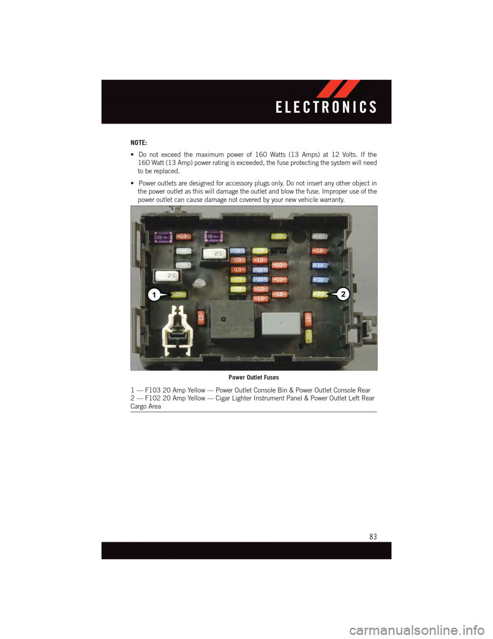
Power Outlet Fuses
1—F10320AmpYellow—PowerOutletConsoleBin&PowerOutletConsoleRear2—F10220AmpYellow—CigarLighterInstrumentPanel&PowerOutletLeftRearCargo Area
ELECTRONICS
83
Page 88 of 140
ROADSIDE ASSISTANCE
Dial toll-free 1-800-521-2779 for U.S. Residents or 1-800-363-4869 for Canadian
Residents.
•Provideyourname,vehicleidentificationnumber,licenseplatenumber,andyour
location, including the telephone number from which you are calling.
•Brieflydescribethenatureoftheproblemandanswerafewsimplequestions.
•Youwillbegiventhenameoftheserviceproviderandanestimatedtimeofarrival.If
you feel you are in an “unsafe situation”, please let us know. With your consent, we will
contact local police or safety authorities.
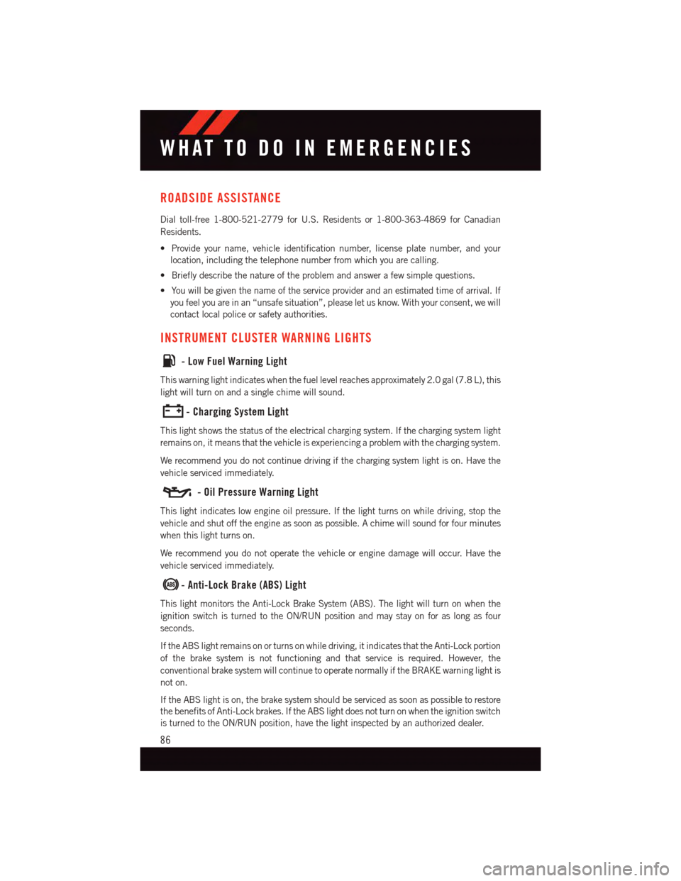
INSTRUMENT CLUSTER WARNING LIGHTS
-LowFuelWarningLight
This warning light indicates when the fuel level reaches approximately 2.0 gal (7.8 L), this
light will turn on and a single chime will sound.
-ChargingSystemLight
This light shows the status of the electrical charging system. If the charging system light
remains on, it means that the vehicle is experiencing a problem with the charging system.
We recommend you do not continue driving if the charging system light is on. Have the
vehicle serviced immediately.
-OilPressureWarningLight
This light indicates low engine oil pressure. If the light turns on while driving, stop the
vehicle and shut off the engine as soon as possible. A chime will sound for four minutes
when this light turns on.
We recommend you do not operate the vehicle or engine damage will occur. Have the
vehicle serviced immediately.
-Anti-LockBrake(ABS)Light
This light monitors the Anti-Lock Brake System (ABS). The light will turn on when the
ignition switch is turned to the ON/RUN position and may stay on for as long as four
seconds.
If the ABS light remains on or turns on while driving, it indicates that the Anti-Lock portion
of the brake system is not functioning and that service is required. However, the
conventional brake system will continue to operate normally if the BRAKE warning light is
not on.
If the ABS light is on, the brake system should be serviced as soon as possible to restore
the benefits of Anti-Lock brakes. If the ABS light does not turn on when the ignition switch
is turned to the ON/RUN position, have the light inspected by an authorized dealer.
WHAT TO DO IN EMERGENCIES
86
Page 89 of 140
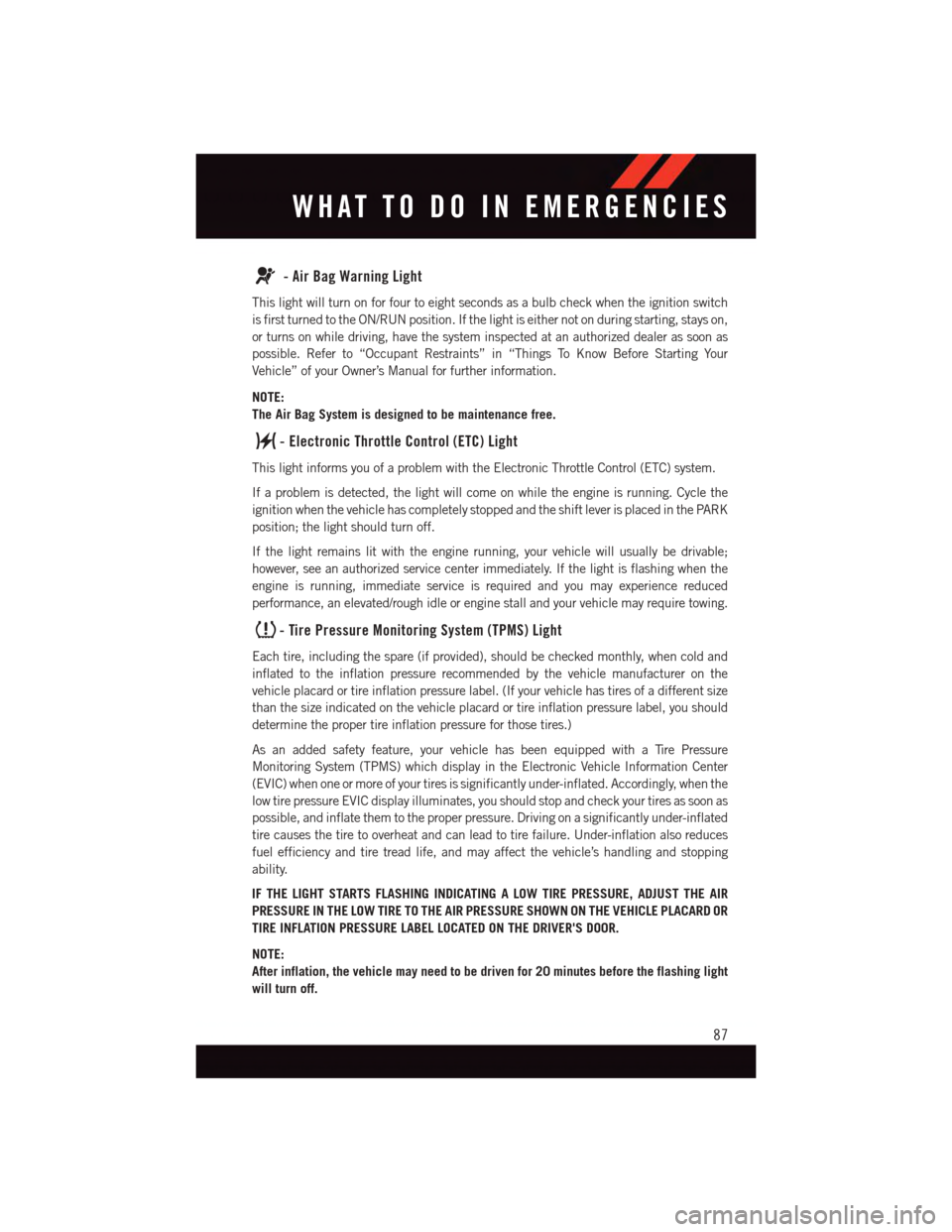
-AirBagWarningLight
This light will turn on for four to eight seconds as a bulb check when the ignition switch
is first turned to the ON/RUN position. If the light is either not on during starting, stays on,
or turns on while driving, have the system inspected at an authorized dealer as soon as
possible. Refer to “Occupant Restraints” in “Things To Know Before Starting Your
Vehicle” of your Owner’s Manual for further information.
NOTE:
The Air Bag System is designed to be maintenance free.
-ElectronicThrottleControl(ETC)Light
This light informs you of a problem with the Electronic Throttle Control (ETC) system.
If a problem is detected, the light will come on while the engine is running. Cycle the
ignition when the vehicle has completely stopped and the shift lever is placed in the PARK
position; the light should turn off.
If the light remains lit with the engine running, your vehicle will usually be drivable;
however, see an authorized service center immediately. If the light is flashing when the
engine is running, immediate service is required and you may experience reduced
performance, an elevated/rough idle or engine stall and your vehicle may require towing.
-TirePressureMonitoringSystem(TPMS)Light
Each tire, including the spare (if provided), should be checked monthly, when cold and
inflated to the inflation pressure recommended by the vehicle manufacturer on the
vehicle placard or tire inflation pressure label. (If your vehicle has tires of a different size
than the size indicated on the vehicle placard or tire inflation pressure label, you should
determine the proper tire inflation pressure for those tires.)
As an added safety feature, your vehicle has been equipped with a Tire Pressure
Monitoring System (TPMS) which display in the Electronic Vehicle Information Center
(EVIC) when one or more of your tires is significantly under-inflated. Accordingly, when the
low tire pressure EVIC display illuminates, you should stop and check your tires as soon as
possible, and inflate them to the proper pressure. Driving on a significantly under-inflated
tire causes the tire to overheat and can lead to tire failure. Under-inflation also reduces
fuel efficiency and tire tread life, and may affect the vehicle’s handling and stopping
ability.
IF THE LIGHT STARTS FLASHING INDICATING A LOW TIRE PRESSURE, ADJUST THE AIR
PRESSURE IN THE LOW TIRE TO THE AIR PRESSURE SHOWN ON THE VEHICLE PLACARD OR
TIRE INFLATION PRESSURE LABEL LOCATED ON THE DRIVER'S DOOR.
NOTE:
After inflation, the vehicle may need to be driven for 20 minutes before the flashing light
will turn off.
WHAT TO DO IN EMERGENCIES
87