turn signal DODGE JOURNEY 2015 1.G User Guide
[x] Cancel search | Manufacturer: DODGE, Model Year: 2015, Model line: JOURNEY, Model: DODGE JOURNEY 2015 1.GPages: 140, PDF Size: 23.09 MB
Page 3 of 140
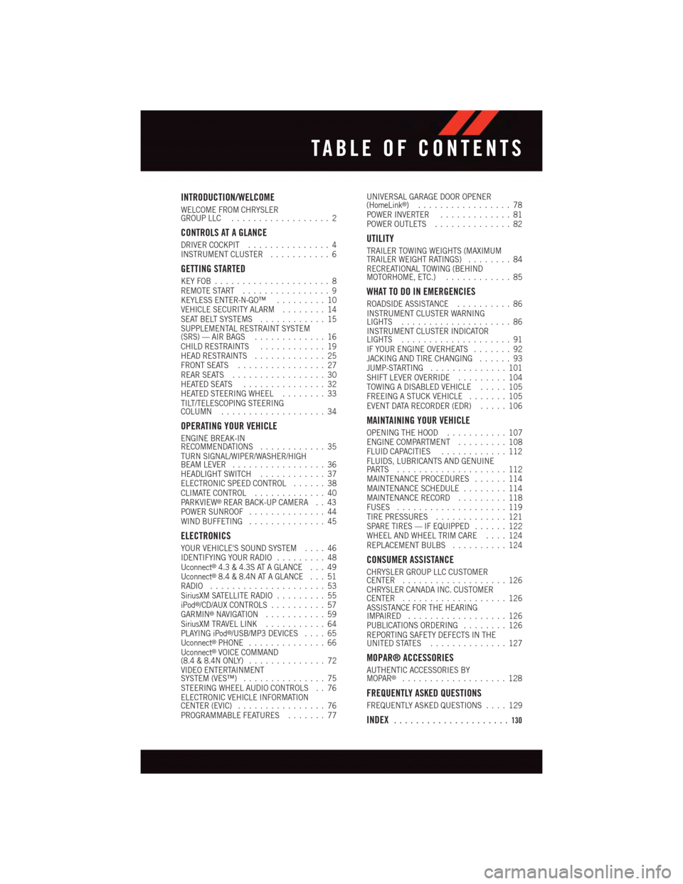
INTRODUCTION/WELCOME
WELCOME FROM CHRYSLERGROUP LLC..................2
CONTROLS AT A GLANCE
DRIVER COCKPIT...............4INSTRUMENT CLUSTER...........6
GETTING STARTED
KEY FOB . . . . . . . . . . . . . . . . . . . . . 8REMOTE START . . . . . . . . . . . . . . . . 9KEYLESS ENTER-N-GO™.........10VEHICLE SECURITY ALARM........14SEAT BELT SYSTEMS............15SUPPLEMENTAL RESTRAINT SYSTEM(SRS) — AIR BAGS.............16CHILD RESTRAINTS............19HEAD RESTRAINTS.............25FRONT SEATS................27REAR SEATS.................30HEATED SEATS . . . . . . . . . . . . . . . 32HEATED STEERING WHEEL........33TILT/TELESCOPING STEERINGCOLUMN...................34
OPERATING YOUR VEHICLE
ENGINE BREAK-INRECOMMENDATIONS............35TURN SIGNAL/WIPER/WASHER/HIGHBEAM LEVER.................36HEADLIGHT SWITCH............37ELECTRONIC SPEED CONTROL......38CLIMATE CONTROL.............40PA R K V I E W®REAR BACK-UP CAMERA . . 43POWER SUNROOF..............44WIND BUFFETING..............45
ELECTRONICS
YOUR VEHICLE'S SOUND SYSTEM....46IDENTIFYING YOUR RADIO.........48Uconnect®4.3 & 4.3S AT A GLANCE . . . 49Uconnect®8.4 & 8.4N AT A GLANCE . . . 51RADIO.....................53SiriusXM SATELLITE RADIO.........55iPod®/CD/AUX CONTROLS..........57GARMIN®NAVIGATION...........59SiriusXM TRAVEL LINK...........64PLAYING iPod®/USB/MP3 DEVICES....65Uconnect®PHONE..............66Uconnect®VOICE COMMAND(8.4 & 8.4N ONLY)..............72VIDEO ENTERTAINMENTSYSTEM (VES™)...............75STEERING WHEEL AUDIO CONTROLS . . 76ELECTRONIC VEHICLE INFORMATIONCENTER (EVIC)................76PROGRAMMABLE FEATURES.......77
UNIVERSAL GARAGE DOOR OPENER(HomeLink®).................78POWER INVERTER.............81POWER OUTLETS..............82
UTILITY
TRAILER TOWING WEIGHTS (MAXIMUMTRAILER WEIGHT RATINGS)........84RECREATIONAL TOWING (BEHINDMOTORHOME, ETC.)............85
WHAT TO DO IN EMERGENCIES
ROADSIDE ASSISTANCE..........86INSTRUMENT CLUSTER WARNINGLIGHTS....................86INSTRUMENT CLUSTER INDICATORLIGHTS....................91IF YOUR ENGINE OVERHEATS.......92JACKING AND TIRE CHANGING......93JUMP-STARTING..............101SHIFT LEVER OVERRIDE.........104TOWING A DISABLED VEHICLE.....105FREEING A STUCK VEHICLE.......105EVENT DATA RECORDER (EDR).....106
MAINTAINING YOUR VEHICLE
OPENING THE HOOD...........107ENGINE COMPARTMENT.........108FLUID CAPACITIES............112FLUIDS, LUBRICANTS AND GENUINEPA RT S . . . . . . . . . . . . . . . . . . . . 1 1 2MAINTENANCE PROCEDURES......114MAINTENANCE SCHEDULE........114MAINTENANCE RECORD.........118FUSES....................119TIRE PRESSURES.............121SPARE TIRES — IF EQUIPPED......122WHEEL AND WHEEL TRIM CARE....124REPLACEMENT BULBS..........124
CONSUMER ASSISTANCE
CHRYSLER GROUP LLC CUSTOMERCENTER...................126CHRYSLER CANADA INC. CUSTOMERCENTER...................126ASSISTANCE FOR THE HEARINGIMPAIRED..................126PUBLICATIONS ORDERING........126REPORTING SAFETY DEFECTS IN THEUNITED STATES..............127
MOPAR® ACCESSORIES
AUTHENTIC ACCESSORIES BYMOPAR®...................128
FREQUENTLY ASKED QUESTIONS
FREQUENTLY ASKED QUESTIONS....129
INDEX.....................130
TABLE OF CONTENTS
Page 6 of 140
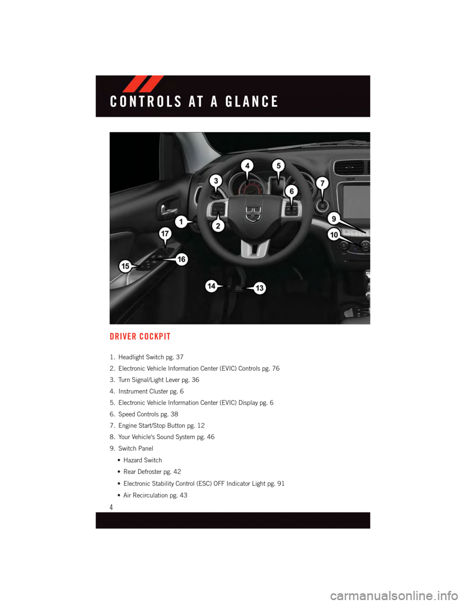
DRIVER COCKPIT
1. Headlight Switch pg. 37
2. Electronic Vehicle Information Center (EVIC) Controls pg. 76
3. Turn Signal/Light Lever pg. 36
4. Instrument Cluster pg. 6
5. Electronic Vehicle Information Center (EVIC) Display pg. 6
6. Speed Controls pg. 38
7. Engine Start/Stop Button pg. 12
8. Your Vehicle's Sound System pg. 46
9. Switch Panel
•HazardSwitch
•RearDefrosterpg.42
•ElectronicStabilityControl(ESC)OFFIndicatorLightpg.91
•AirRecirculationpg.43
CONTROLS AT A GLANCE
4
Page 10 of 140
KEY FOB
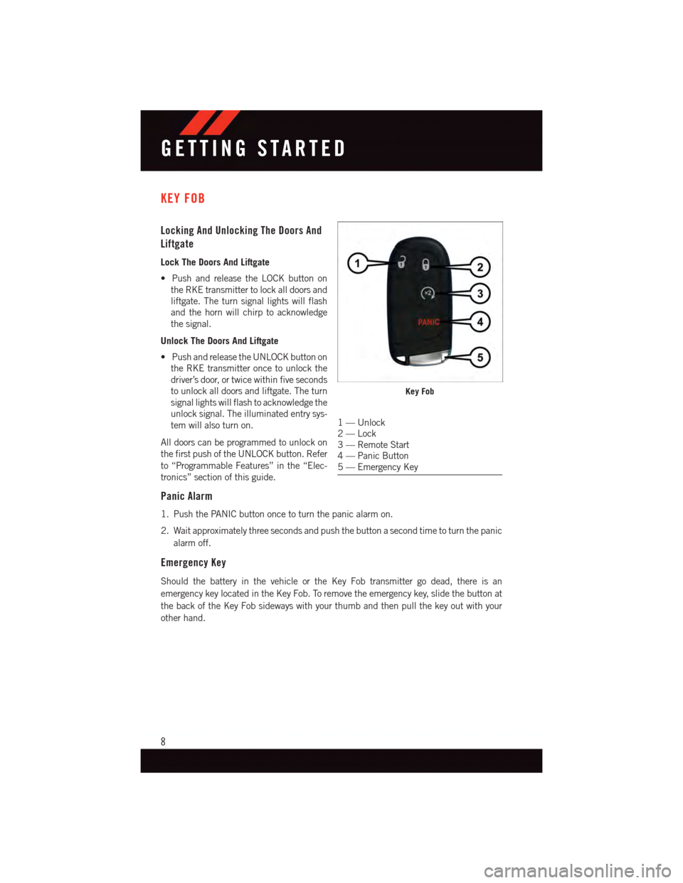
Locking And Unlocking The Doors And
Liftgate
Lock The Doors And Liftgate
•PushandreleasetheLOCKbuttonon
the RKE transmitter to lock all doors and
liftgate. The turn signal lights will flash
and the horn will chirp to acknowledge
the signal.
Unlock The Doors And Liftgate
•PushandreleasetheUNLOCKbuttonon
the RKE transmitter once to unlock the
driver’s door, or twice within five seconds
to unlock all doors and liftgate. The turn
signal lights will flash to acknowledge the
unlock signal. The illuminated entry sys-
tem will also turn on.
All doors can be programmed to unlock on
the first push of the UNLOCK button. Refer
to “Programmable Features” in the “Elec-
tronics” section of this guide.
Panic Alarm
1. Push the PANIC button once to turn the panic alarm on.
2. Wait approximately three seconds and push the button a second time to turn the panic
alarm off.
Emergency Key
Should the battery in the vehicle or the Key Fob transmitter go dead, there is an
emergency key located in the Key Fob. To remove the emergency key, slide the button at
the back of the Key Fob sideways with your thumb and then pull the key out with your
other hand.
Key Fob
1—Unlock2—Lock3—RemoteStart4—PanicButton5—EmergencyKey
GETTING STARTED
8
Page 38 of 140
TURN SIGNAL/WIPER/WASHER/HIGH BEAM LEVER
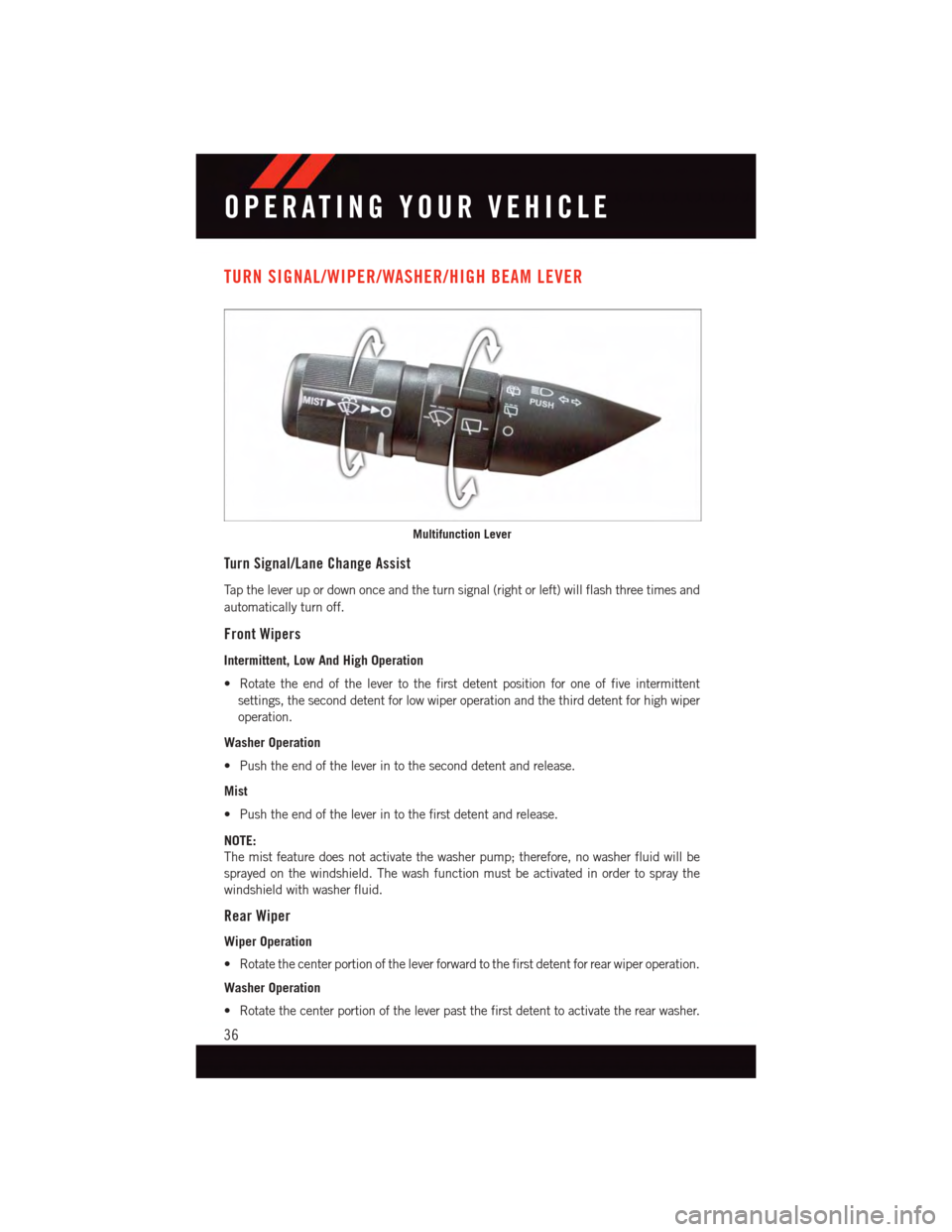
Turn Signal/Lane Change Assist
Ta p t h e l e v e r u p o r d o w n o n c e a n d t h e t u r n s i g n a l ( r i g h t o r l e f t ) w i l l f l a s h t h r e e t i m e s a n d
automatically turn off.
Front Wipers
Intermittent, Low And High Operation
•Rotatetheendofthelevertothefirstdetentpositionforoneoffiveintermittent
settings, the second detent for low wiper operation and the third detent for high wiper
operation.
Washer Operation
•Pushtheendoftheleverintotheseconddetentandrelease.
Mist
•Pushtheendoftheleverintothefirstdetentandrelease.
NOTE:
The mist feature does not activate the washer pump; therefore, no washer fluid will be
sprayed on the windshield. The wash function must be activated in order to spray the
windshield with washer fluid.
Rear Wiper
Wiper Operation
•Rotatethecenterportionoftheleverforwardtothefirstdetentforrearwiperoperation.
Washer Operation
•Rotatethecenterportionoftheleverpastthefirstdetenttoactivatetherearwasher.
Multifunction Lever
OPERATING YOUR VEHICLE
36
Page 74 of 140
NOTE:
To a c c e s s h e l p , p r e s s t h e U c o n n e c t®Phonebutton on the steering wheel and say
"help." Press the display or push eitherorbutton and say "cancel" to cancel
the help session.
Voice Text Reply
•Uconnect®Phone can read or send new text messages on your mobile phone.
•YourmobilephonemustsupportVoiceTextReplyoverBluetooth®to use this feature.
If the Uconnect®Phone determines your mobile phone is not compatible with Voice
Te x t R e p l y m e s s a g i n g o v e r B l u e t o o t h®,the“Messaging”buttonwillbegreyedoutand
the feature will not be available for use.
NOTE:
•For mobile phone compatibility and pairing instructions, please visit
UconnectPhone.com
•Uconnect®Phone Voice Text Reply is only available when the vehicle is not moving.
WARNING!
•Anyvoicecommandedsystemshouldbeusedonlyinsafedrivingconditions
following applicable laws regarding phone use. Your attention should be focused on
safely operating the vehicle. Failure to do so may result in a collision causing you
and others to be severely injured or killed.
•Inanemergency,touseUconnect®Phone, your mobile phone must be:
•turnedon,
•pairedtoUconnect®Phone,
•andhavenetworkcoverage.
Uconnect® VOICE COMMAND (8.4 & 8.4N ONLY)
•IftheUconnect®Voice Commandbutton exists on your steering wheel, then
you have the Voice Command feature.
•TheVoiceCommandfeatureletsyoukeepyourhandsonthesteeringwheel,andyour
eyes on the road.
•WhenyoupresstheVoiceCommandbuttonlocated on the radio faceplate or
steering wheel, you will hear a beep. The beep is your signal to give a command. If you
do not know what commands to say, you can say "help" and the system will provide
options to you. If you ever wish to interrupt the system while it lists options, press the
Voice Command button,listenfortheBEEP,andsayyourcommand.
•Youcan“chain”commandstogetherforfasterresults.Say“PlaytheartistScott
Joplin”, for example.
ELECTRONICS
72
Page 81 of 140
NOTE:
Erasing all channels should only be performed when programming HomeLink®for the first
time. Do not erase channels when programming additional buttons.
If you have any problems, or require assistance, please call toll-free 1-800-355-3515 or,
on the Internet at for information or assistance.
Programming A Rolling Code
NOTE:
For programming Garage Door Openers that were manufactured after 1995. These Garage
Door Openers can be identified by the “LEARN” or “TRAIN” button located where the
hanging antenna is attached to the Garage Door Opener. It is NOT the button that is
normally used to open and close the door. The name and color of the button may vary by
manufacturer.
1. Place the ignition switch into the ON/RUN position.
2. Place the hand-held transmitter 1 to 3 inches (3 to 8 cm) away from the HomeLink®
button you wish to program while keeping the HomeLink®indicator light in view.
3. Push and hold the HomeLink®button you want to program while you push and hold
the hand-held transmitter button.
4. Continue to hold both buttons and observe the indicator light. The HomeLink®
indicator will flash slowly and then rapidly after HomeLink®has received the fre-
quency signal from the hand-held transmitter. Release both buttons after the indicator
light changes from slow to rapid.
5. At the garage door opener motor (in the garage), locate the “LEARN” or “TRAINING”
button. This can usually be found where the hanging antenna wire is attached to the
garage door opener motor. Firmly push and release the “LEARN” or “TRAINING”
button.
NOTE:
Yo u h a v e 3 0 s e c o n d s i n w h i c h t o i n i t i a t e t h e n e x t s t e p a f t e r t h e L E A R N b u t t o n h a s b e e n
pushed.
6. Return to the vehicle and push the programmed HomeLink®button twice (holding the
button for two seconds each time). If the device is plugged in and activates,
programming is complete.
NOTE:
If the device does not activate, push the button a third time (for two seconds) to complete
the training.
7. To program the remaining two HomeLink®buttons, repeat each step for each
remaining button. DO NOT erase the channels.
ELECTRONICS
79
Page 82 of 140
Programming A Non-Rolling Code
NOTE:
For programming Garage Door Openers manufactured before 1995.
1. Turn the ignition switch to the ON/RUN position.
2. Place the hand-held transmitter 1 to 3 inches (3 to 8 cm) away from the HomeLink®
button you wish to program while keeping the HomeLink®indicator light in view.
3. Push and hold the HomeLink®button you want to program while you push and hold
the hand-held transmitter button.
4. Continue to hold both buttons and observe the indicator light. The HomeLink®
indicator will flash slowly and then rapidly after HomeLink®has received the fre-
quency signal from the hand-held transmitter. Release both buttons after the indicator
light changes from slow to rapid.
5. Push and hold the programmed HomeLink®button and observe the indicator light. If
the indicator light stays on constantly, programming is complete and the garage door
(or device) should activate when the HomeLink®button is pushed.
6. To program the two remaining HomeLink®buttons, repeat each step for each
remaining button. DO NOT erase the channels.
Using HomeLink®
To o p e r a t e , p u s h a n d r e l e a s e t h e p r o g r a m m e d H o m e L i n k®button. Activation will now
occur for the programmed device (e.g., garage door opener, gate operator, security system,
entry door lock, home/office lighting, etc.,). The hand-held transmitter of the device may
also be used at any time.
WARNING!
•Yourmotorizeddoororgatewillopenandclosewhileyouareprogrammingthe
universal transceiver. Do not program the transceiver if people or pets are in the
path of the door or gate.
•Donotrunyourvehicleinaclosedgarageorconfinedareawhileprogrammingthe
transceiver. Exhaust gas from your vehicle contains Carbon Monoxide (CO) which is
odorless and colorless. Carbon Monoxide is poisonous when inhaled and can cause
you and others to be severely injured or killed.
ELECTRONICS
80
Page 90 of 140
Please note that the TPMS is not a substitute for proper tire maintenance, and it is the
driver’s responsibility to maintain correct tire pressure, even if under-inflation has not
reached the level to trigger illumination of the TPMS low EVIC display.
Yo u r v e h i c l e h a s a l s o b e e n e q u i p p e d w i t h a T P M S m a l f u n c t i o n i n d i c a t o r t o i n d i c a t e w h e n
the system is not operating properly. The TPMS malfunction indicator is combined with
the low tire pressure telltale. When the system detects a malfunction, the telltale will flash
for approximately one minute and then remain continuously illuminated. This sequence
will continue each time the vehicle is restarted as long as the malfunction exists.
When the malfunction indicator is illuminated, the system may not be able to detect or
signal low tire pressure as intended. TPMS malfunctions may occur for a variety of
reasons, including the installation of replacement or alternate tires or wheels on the
vehicle that prevent the TPMS from functioning properly. Always check the TPMS
malfunction telltale after replacing one or more tires or wheels on your vehicle, to ensure
that the replacement or alternate tires and wheels allow the TPMS to continue to function
properly.
NOTE:
Ti r e p r e s s u r e s c h a n g e b y a p p r o x i m a t e l y 1 p s i ( 7 k P a ) p e r 1 2 ° F ( 7 ° C ) o f a i r t e m p e r a t u r e
change. Keep this in mind when checking tire pressure inside a garage, especially in the
Winter. Example: If garage temperature is 68°F (20°C) and the outside temperature is
32°F (0°C), then the cold tire inflation pressure should be increased by 3 psi (21 kPa),
which equals 1 psi (7 kPa) for every 12°F (7°C) for this outside temperature condition.
CAUTION!
The TPMS has been optimized for the original equipment tires and wheels. TPMS
pressures and warning have been established for the tire size equipped on your vehicle.
Undesirable system operation or sensor damage may result when using replacement
equipment that is not of the same size, type, and/or style. Aftermarket wheels can
cause sensor damage. Do not use tire sealant from a can, or balance beads if your
vehicle is equipped with a TPMS, as damage to the sensors may result.
-EngineTemperatureWarningLight
This light warns of an overheated engine condition.
If the light turns on and a warning chime sounds while driving, safely pull over and stop
the vehicle. If the A/C system is on, turn it off. Also, shift the transmission into NEUTRAL
and idle the vehicle. If the temperature reading does not return to normal, turn the engine
off immediately.
We recommend that you do not operate the vehicle or engine damage will occur. Have the
vehicle serviced immediately.
WHAT TO DO IN EMERGENCIES
88
Page 93 of 140
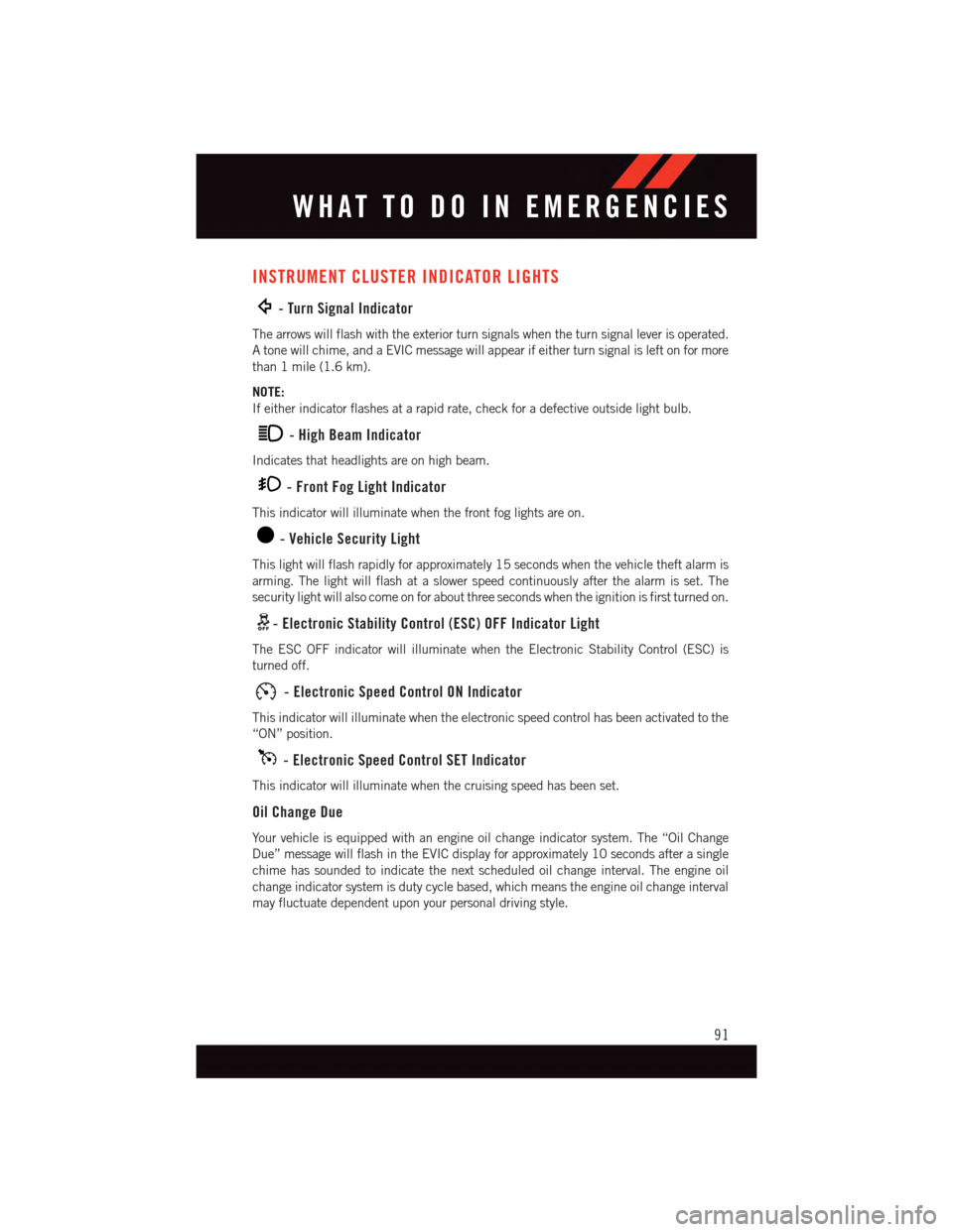
INSTRUMENT CLUSTER INDICATOR LIGHTS
-TurnSignalIndicator
The arrows will flash with the exterior turn signals when the turn signal lever is operated.
Atonewillchime,andaEVICmessagewillappearifeitherturnsignalisleftonformore
than 1 mile (1.6 km).
NOTE:
If either indicator flashes at a rapid rate, check for a defective outside light bulb.
-HighBeamIndicator
Indicates that headlights are on high beam.
-FrontFogLightIndicator
This indicator will illuminate when the front fog lights are on.
-VehicleSecurityLight
This light will flash rapidly for approximately 15 seconds when the vehicle theft alarm is
arming. The light will flash at a slower speed continuously after the alarm is set. The
security light will also come on for about three seconds when the ignition is first turned on.
-ElectronicStabilityControl(ESC)OFFIndicatorLight
The ESC OFF indicator will illuminate when the Electronic Stability Control (ESC) is
turned off.
-ElectronicSpeedControlONIndicator
This indicator will illuminate when the electronic speed control has been activated to the
“ON” position.
-ElectronicSpeedControlSETIndicator
This indicator will illuminate when the cruising speed has been set.
Oil Change Due
Yo u r v e h i c l e i s e q u i p p e d w i t h a n e n g i n e o i l c h a n g e i n d i c a t o r s y s t e m . T h e “ O i l C h a n g e
Due” message will flash in the EVIC display for approximately 10 seconds after a single
chime has sounded to indicate the next scheduled oil change interval. The engine oil
change indicator system is duty cycle based, which means the engine oil change interval
may fluctuate dependent upon your personal driving style.
WHAT TO DO IN EMERGENCIES
91
Page 126 of 140
WHEEL AND WHEEL TRIM CARE
All wheels and wheel trim, especially aluminum and chrome plated wheels, should be
cleaned regularly with a mild soap and water to prevent corrosion.
To r e m o v e h e a v y s o i l a n d / o r e x c e s s i v e b r a k e d u s t , u s e M O PA R®Wheel Cleaner or
equivalent or select a non-abrasive, non-acidic cleaner.
CAUTION!
Do not use scouring pads, steel wool, a bristle brush, or metal polishes. Do not use oven
cleaner. These products may damage the wheel's protective finish. Avoid automatic car
washes that use acidic solutions or harsh brushes that may damage the wheel's
protective finish. Only MOPAR®Wheel Cleaner or equivalent is recommended.
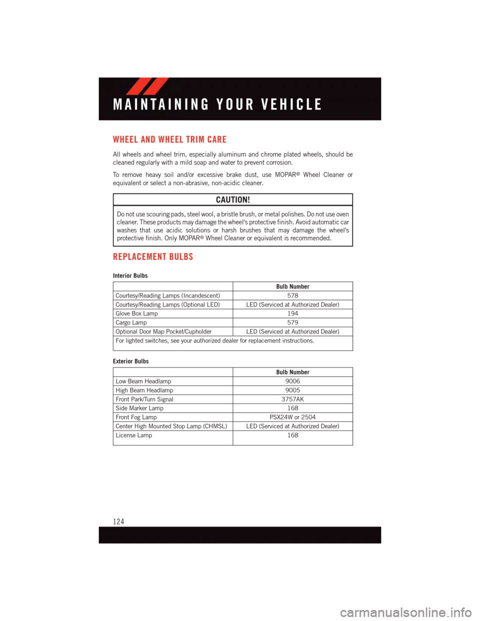
REPLACEMENT BULBS
Interior Bulbs
Bulb Number
Courtesy/Reading Lamps (Incandescent)578
Courtesy/Reading Lamps (Optional LED) LED (Serviced at Authorized Dealer)
Glove Box Lamp194
Cargo Lamp579
Optional Door Map Pocket/CupholderLED (Serviced at Authorized Dealer)
For lighted switches, see your authorized dealer for replacement instructions.
Exterior Bulbs
Bulb Number
Low Beam Headlamp9006
High Beam Headlamp9005
Front Park/Turn Signal3757AK
Side Marker Lamp168
Front Fog LampPSX24W or 2504
Center High Mounted Stop Lamp (CHMSL) LED (Serviced at Authorized Dealer)
License Lamp168
MAINTAINING YOUR VEHICLE
124