warning light DODGE JOURNEY 2020 Owners Manual
[x] Cancel search | Manufacturer: DODGE, Model Year: 2020, Model line: JOURNEY, Model: DODGE JOURNEY 2020Pages: 396, PDF Size: 25.53 MB
Page 5 of 396
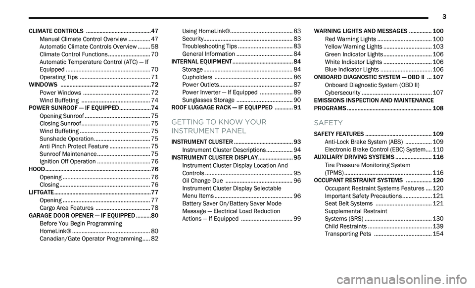
3
CLIMATE CONTROLS ...........................................47
Manual Climate Control Overview .. ............ 47
Automatic Climate Controls Overview . . ...... 58
Climate Control Functions . . ......................... 70
Automatic Temperature Control (ATC) — If
Equipped . ..................................................... 70
O
perating Tips . . ........................................... 71
WINDOWS . . ..........................................................72
Power Windows .. ......................................... 72
Wind Buffeting . . .......................................... 74
POWER SUNROOF — IF EQUIPPED. . ...................74
Opening Sunroof .. ........................................ 75
Closing Sunroof . . .......................................... 75
Wind Buffeting . . ........................................... 75
Sunshade Operation. . .................................. 75
Anti Pinch Protect Feature . . ........................ 75
Sunroof Maintenance . . ................................ 75
Ignition Off Operation . . ................................ 76
HOOD. .....................................................................76
O pening ........................................................ 76
C losing . ......................................................... 76
L
IFTGATE . ...............................................................77
O pening ........................................................ 77
C argo Area Features . . ................................. 78
GARAGE DOOR OPENER — IF EQUIPPED . . ........80
Before You Begin Programming
HomeLink® . .
................................................ 80
Canadian/Gate Operator Programming . . ... 82Using HomeLink®.
.
...................................... 83
Security. ........................................................ 83
T roubleshooting Tips . . ................................. 83
General Information . . .................................. 84
INTERNAL EQUIPMENT . . ...................................... 84
Storage ......................................................... 84
C upholders . . ................................................ 86
Power Outlets. . ............................................. 87
Power Inverter — If Equipped . . ................... 89
Sunglasses Storage . . .................................. 90
ROOF LUGGAGE RACK — IF EQUIPPED . . .......... 91
GETTING TO KNOW YOUR
INSTRUMENT PANEL
INSTRUMENT CLUSTER ....................................... 93
Instrument Cluster Descriptions .. ............... 94
INSTRUMENT CLUSTER DISPLAY. . ..................... 95
Instrument Cluster Display Location And
Controls . ....................................................... 95
O
il Change Due . . ......................................... 96
Instrument Cluster Display Selectable
Menu Items . .
................................................ 96
Battery Saver On/Battery Saver Mode
Message — Electrical Load Reduction
Actions — If Equipped . .
............................... 99 WARNING LIGHTS AND MESSAGES .
.
............. 100
Red Warning Lights .. ................................. 100
Yellow Warning Lights . . ............................. 103
Green Indicator Lights . . ............................. 106
White Indicator Lights . . ............................. 106
Blue Indicator Lights . . ............................... 106
ONBOARD DIAGNOSTIC SYSTEM — OBD II . . . 107
Onboard Diagnostic System (OBD II)
Cybersecurity . .
........................................... 107
EMISSIONS INSPECTION AND MAINTENANCE
PROGRAMS . .
...................................................... 108
SAFETY
SAFETY FEATURES ............................................ 109
Anti-Lock Brake System (ABS) .. ............... 109
Electronic Brake Control (EBC) System. . .. 110
AUXILIARY DRIVING SYSTEMS . . ...................... 116
Tire Pressure Monitoring System
(TPMS) . ....................................................... 116
O
CCUPANT RESTRAINT SYSTEMS . . ............... 120
Occupant Restraint Systems Features .. .. 120
Important Safety Precautions . . ................. 121
Seat Belt Systems . . .................................. 121
Supplemental Restraint
Systems (SRS) . .
......................................... 130
Child Restraints . . ....................................... 139
Transporting Pets . . ................................... 154
Page 10 of 396
8
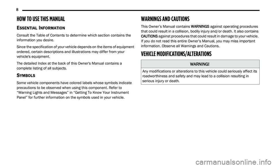
HOW TO USE THIS MANUAL
ESSENTIAL INFORMATION
Consult the Table of Contents to determine which section contains the
information you desire.
Since the specification of your vehicle depends on the items of equipment
or
dered, certain descriptions and illustrations may differ from your
vehicle's equipment.
The detailed Index at the back of this Owner's Manual contains a
c o
mplete listing of all subjects.
SYMBOLS
Some vehicle components have colored labels whose symbols indicate
precautions to be observed when using this component. Refer to
“Warning Lights and Messages” in “Getting To Know Your Instrument
Panel” for further information on the symbols used in your vehicle.
WARNINGS AND CAUTIONS
This Owner’s Manual contains WARNINGS against operating procedures
that could result in a collision, bodily injury and/or death. It also contains
CAUTIONS against procedures that could result in damage to your vehicle.
If you do not read this entire Owner’s Manual, you may miss important
information. Observe all Warnings and Cautions.
VEHICLE MODIFICATIONS/ALTERATIONS
WARNING!
Any modifications or alterations to this vehicle could seriously affect its
roadworthiness and safety and may lead to a collision resulting in
serious injury or death.
Page 16 of 396
14 GETTING TO KNOW YOUR VEHICLE
(Continued)
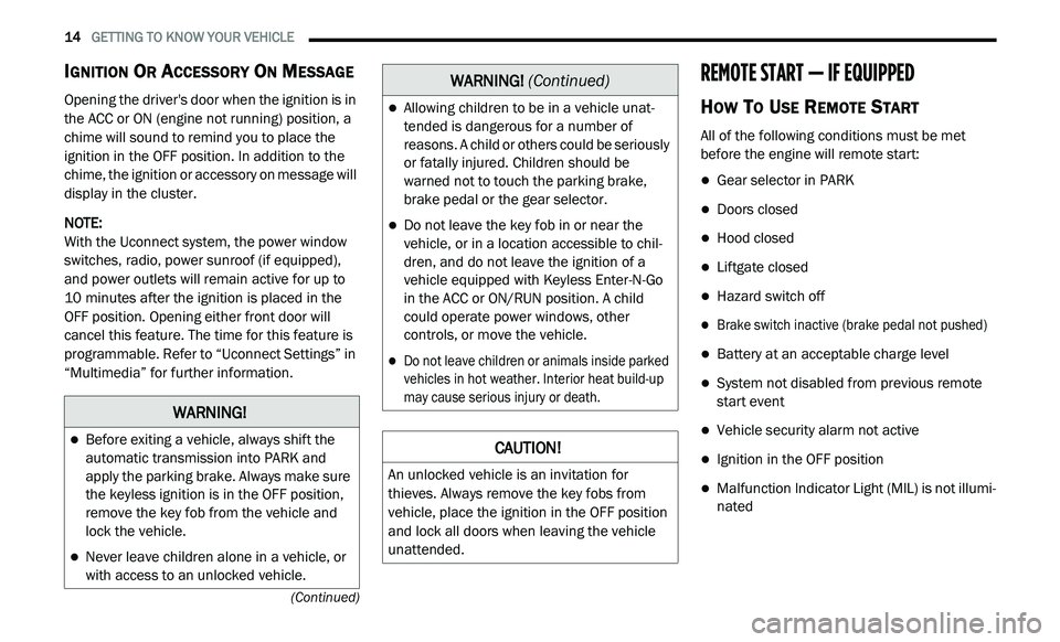
IGNITION OR ACCESSORY ON MESSAGE
Opening the driver's door when the ignition is in
the ACC or ON (engine not running) position, a
chime will sound to remind you to place the
ignition in the OFF position. In addition to the
chime, the ignition or accessory on message will
display in the cluster.
NOTE:
With the Uconnect system, the power window
s w
itches, radio, power sunroof (if equipped),
and power outlets will remain active for up to
10 minutes after the ignition is placed in the
O F
F position. Opening either front door will
cancel this feature. The time for this feature is
programmable. Refer to “Uconnect Settings” in
“Multimedia” for further information.
REMOTE START — IF EQUIPPED
HOW TO USE REMOTE START
All of the following conditions must be met
before the engine will remote start:
Gear selector in PARK
Doors closed
Hood closed
Liftgate closed
Hazard switch off
Brake switch inactive (brake pedal not pushed)
Battery at an acceptable charge level
System not disabled from previous remote
start event
Vehicle security alarm not active
Ignition in the OFF position
Malfunction Indicator Light (MIL) is not illumi -
nated
WARNING!
Before exiting a vehicle, always shift the
automatic transmission into PARK and
apply the parking brake. Always make sure
the keyless ignition is in the OFF position,
remove the key fob from the vehicle and
lock the vehicle.
Never leave children alone in a vehicle, or
with access to an unlocked vehicle.
Allowing children to be in a vehicle unat -
tended is dangerous for a number of
r e
asons. A child or others could be seriously
or fatally injured. Children should be
warned not to touch the parking brake,
brake pedal or the gear selector.
Do not leave the key fob in or near the
vehicle, or in a location accessible to chil-
dren, and do not leave the ignition of a
v e
hicle equipped with Keyless Enter-N-Go
in the ACC or ON/RUN position. A child
could operate power windows, other
controls, or move the vehicle.
Do not leave children or animals inside parked
vehicles in hot weather. Interior heat build-up
may cause serious injury or death.
CAUTION!
An unlocked vehicle is an invitation for
thieves. Always remove the key fobs from
vehicle, place the ignition in the OFF position
and lock all doors when leaving the vehicle
unattended.
WARNING! (Continued)
Page 17 of 396
GETTING TO KNOW YOUR VEHICLE 15
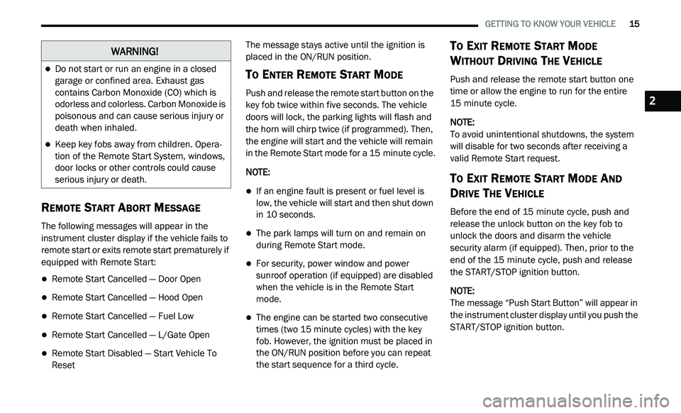
REMOTE START ABORT MESSAGE
The following messages will appear in the
instrument cluster display if the vehicle fails to
remote start or exits remote start prematurely if
equipped with Remote Start:
Remote Start Cancelled — Door Open
Remote Start Cancelled — Hood Open
Remote Start Cancelled — Fuel Low
Remote Start Cancelled — L/Gate Open
Remote Start Disabled — Start Vehicle To
Reset The message stays active until the ignition is
p
l
aced in the ON/RUN position.
TO ENTER REMOTE START MODE
Push and release the remote start button on the
key fob twice within five seconds. The vehicle
doors will lock, the parking lights will flash and
the horn will chirp twice (if programmed). Then,
the engine will start and the vehicle will remain
in the Remote Start mode for a 15 minute cycle.
NOTE:
If an engine fault is present or fuel level is
low, the vehicle will start and then shut down
in 10 seconds.
The park lamps will turn on and remain on
during Remote Start mode.
For security, power window and power
sunroof operation (if equipped) are disabled
when the vehicle is in the Remote Start
mode.
The engine can be started two consecutive
times (two 15 minute cycles) with the key
f o
b. However, the ignition must be placed in
the ON/RUN position before you can repeat
the start sequence for a third cycle.
TO EXIT REMOTE START MODE
W
ITHOUT DRIVING THE VEHICLE
Push and release the remote start button one
time or allow the engine to run for the entire
15 minute cycle.
NOTE:
To avoid unintentional shutdowns, the system
wi
ll disable for two seconds after receiving a
valid Remote Start request.
TO EXIT REMOTE START MODE AND
D
RIVE THE VEHICLE
Before the end of 15 minute cycle, push and
re
lease the unlock button on the key fob to
unlock the doors and disarm the vehicle
security alarm (if equipped). Then, prior to the
end of the 15 minute cycle, push and release
t h
e START/STOP ignition button.
NOTE:
The message “Push Start Button” will appear in
t h
e instrument cluster display until you push the
START/STOP ignition button.
WARNING!
Do not start or run an engine in a closed
garage or confined area. Exhaust gas
contains Carbon Monoxide (CO) which is
odorless and colorless. Carbon Monoxide is
poisonous and can cause serious injury or
death when inhaled.
Keep key fobs away from children. Opera -
tion of the Remote Start System, windows,
d o
or locks or other controls could cause
serious injury or death.
2
Page 28 of 396
26 GETTING TO KNOW YOUR VEHICLE
(Continued)
Driver's Seat Height Adjustment — If
Equipped
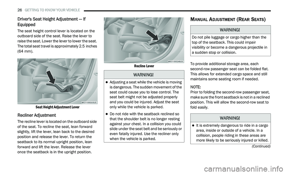
The seat height control lever is located on the
outboard side of the seat. Raise the lever to
raise the seat. Lower the lever to lower the seat.
The total seat travel is approximately 2.5 inches
( 6
4 mm).
Seat Height Adjustment Lever
Recliner Adjustment
The recline lever is located on the outboard side
of the seat. To recline the seat, lean forward
slightly, lift the lever, lean back to the desired
position and release the lever. To return the
seatback to its normal upright position, lean
forward and lift the lever. Release the lever
once the seatback is in the upright position.
Recline Lever
MANUAL ADJUSTMENT (REAR SEATS)
To provide additional storage area, each
second-row passenger seat can be folded flat.
This allows for extended cargo space and still
maintains some seating room if needed.
NOTE:
Prior to folding the second-row passenger seat,
m a
ke sure the front seatback is not in a reclined
position. This will allow the second-row seat to
fold easily.
WARNING!
Adjusting a seat while the vehicle is moving
is dangerous. The sudden movement of the
seat could cause you to lose control. The
seat belt might not be adjusted properly
and you could be injured. Adjust the seat
only while the vehicle is parked.
Do not ride with the seatback reclined so
that the shoulder belt is no longer resting
against your chest. In a collision you could
slide under the seat belt and be seriously or
even fatally injured. Use the recliner only
when the vehicle is parked.
WARNING!
Do not pile luggage or cargo higher than the
top of the seatback. This could impair
visibility or become a dangerous projectile in
a sudden stop or collision.
WARNING!
It is extremely dangerous to ride in a cargo
area, inside or outside of a vehicle. In a
collision, people riding in these areas are
more likely to be seriously injured or killed.
Page 31 of 396
GETTING TO KNOW YOUR VEHICLE 29
Manual Folding Second Row Seat
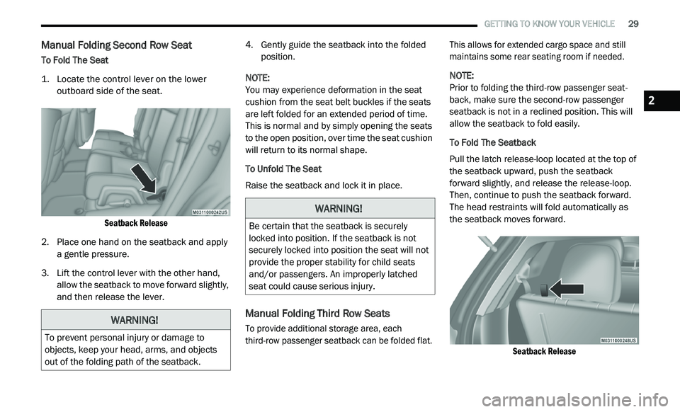
To Fold The Seat
1. L ocate the control lever on the lower
o
utboard side of the seat.
Seatback Release
2. P lace one hand on the seatback and apply
a
gentle pressure.
3. Li ft the control lever with the other hand,
a
llow the seatback to move forward slightly,
and then release the lever. 4. G
ently guide the seatback into the folded
p
osition.
NOTE:
You may experience deformation in the seat
cu
shion from the seat belt buckles if the seats
are left folded for an extended period of time.
This is normal and by simply opening the seats
to the open position, over time the seat cushion
will return to its normal shape.
To Unfold The Seat
Raise the seatback and lock it in place.
Manual Folding Third Row Seats
To provide additional storage area, each
third-row passenger seatback can be folded flat. This allows for extended cargo space and still
maintains some rear seating room if needed.
NOTE:
Prior to folding the third-row passenger seat -
back, make sure the second-row passenger
s e
atback is not in a reclined position. This will
allow the seatback to fold easily.
To Fold The Seatback
Pull the latch release-loop located at the top of
t h
e seatback upward, push the seatback
forward slightly, and release the release-loop.
Then, continue to push the seatback forward.
The head restraints will fold automatically as
the seatback moves forward.
Seatback Release
WARNING!
To prevent personal injury or damage to
objects, keep your head, arms, and objects
out of the folding path of the seatback.
WARNING!
Be certain that the seatback is securely
locked into position. If the seatback is not
securely locked into position the seat will not
provide the proper stability for child seats
and/or passengers. An improperly latched
seat could cause serious injury.
2
Page 38 of 396
36 GETTING TO KNOW YOUR VEHICLE
The heated steering wheel control button is
located within the Uconnect system. You can
gain access to the control button through the
climate screen or the controls screen.
Press the heated steering wheel button
once to turn the heating element on.
Press the heated steering wheel button a
second time to turn the heating element off.
NOTE:
The engine must be running for the heated
s t
eering wheel to operate.
Vehicles Equipped With Remote Start
On models that are equipped with remote start,
t h
e heated steering wheel can be programmed
to come on during a remote start through the
Uconnect system. Refer to “Uconnect Settings”
in “Multimedia” for further information.
MIRRORS
INSIDE DAY/NIGHT MIRROR — IF
E
QUIPPED
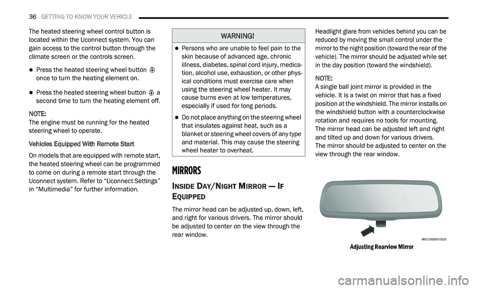
The mirror head can be adjusted up, down, left,
and right for various drivers. The mirror should
be adjusted to center on the view through the
rear window.
Headlight glare from vehicles behind you can be
r
e
duced by moving the small control under the
mirror to the night position (toward the rear of the
vehicle). The mirror should be adjusted while set
in the day position (toward the windshield).
NOTE:
A single ball joint mirror is provided in the
v e
hicle. It is a twist on mirror that has a fixed
position at the windshield. The mirror installs on
the windshield button with a counterclockwise
rotation and requires no tools for mounting.
The mirror head can be adjusted left and right
a n
d tilted up and down for various drivers.
The mirror should be adjusted to center on the
v i
ew through the rear window.
Adjusting Rearview Mirror
WARNING!
Persons who are unable to feel pain to the
skin because of advanced age, chronic
illness, diabetes, spinal cord injury, medica -
tion, alcohol use, exhaustion, or other phys -
ical conditions must exercise care when
u s
ing the steering wheel heater. It may
cause burns even at low temperatures,
especially if used for long periods.
Do not place anything on the steering wheel
that insulates against heat, such as a
blanket or steering wheel covers of any type
and material. This may cause the steering
wheel heater to overheat.
Page 40 of 396
38 GETTING TO KNOW YOUR VEHICLE
OUTSIDE MIRRORS
To receive maximum benefit, adjust the outside
mirrors to center on the adjacent lane of traffic
and a slight overlap of the view obtained from
the inside mirror.
NOTE:
The passenger side convex outside mirror will
g i
ve a much wider view to the rear, and espe -
cially of the lane next to your vehicle.
Outside Mirrors Folding Feature
All outside mirrors are hinged and may be
moved either forward or rearward to resist
damage. The hinges have three detent
positions:
Full forward position
Full rearward position
Normal position
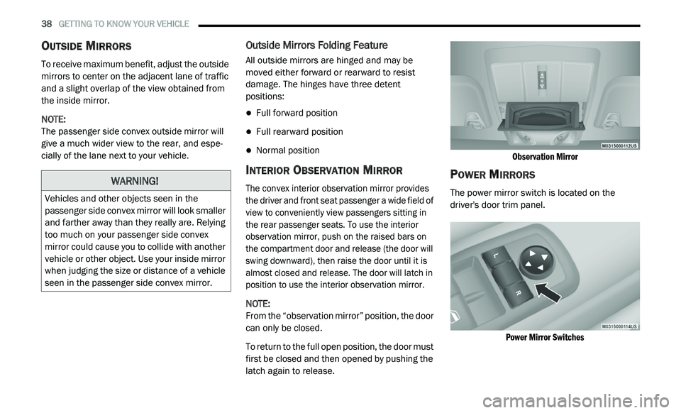
INTERIOR OBSERVATION MIRROR
The convex interior observation mirror provides
the driver and front seat passenger a wide field of
view to conveniently view passengers sitting in
the rear passenger seats. To use the interior
observation mirror, push on the raised bars on
the compartment door and release (the door will
swing downward), then raise the door until it is
almost closed and release. The door will latch in
position to use the interior observation mirror.
NOTE:
From the “observation mirror” position, the door
c a
n only be closed.
To return to the full open position, the door must
f i
rst be closed and then opened by pushing the
latch again to release.
Observation Mirror
POWER MIRRORS
The power mirror switch is located on the
driver's door trim panel.
Power Mirror Switches
WARNING!
Vehicles and other objects seen in the
passenger side convex mirror will look smaller
and farther away than they really are. Relying
too much on your passenger side convex
mirror could cause you to collide with another
vehicle or other object. Use your inside mirror
when judging the size or distance of a vehicle
seen in the passenger side convex mirror.
Page 43 of 396
GETTING TO KNOW YOUR VEHICLE 41
DAYTIME RUNNING LIGHTS (DRLS)
The Daytime Running Lights will turn on the first
time the vehicle is shifted out of PARK, and
remain on unless the parking brake is applied.
Upon returning to the PARK position, the DRLs
will turn off. DRLs will turn off when the ignition
is placed in the OFF position.
NOTE:
The DRLs can be turned on and off using the
Uconnect system, refer to “Uconnect Settings”
in “Multimedia” for further information.
On some vehicles, the Daytime Running
Lights may deactivate or reduce intensity on
one side of the vehicle (when a turn signal is
activated on that side), or on both sides of
the vehicle (when the hazard warning lights
are activated).
HIGH/LOW BEAM SWITCH
Push the multifunction lever away from you to
switch the headlights to high beam. Pull the
multifunction lever toward you to switch the
headlights back to low beam.
FLASH-TO-PASS
You can signal another vehicle with your
headlights by lightly pulling the multifunction
lever toward you. This will cause the high beam
headlights to turn on, and remain on, until the
lever is released.
AUTOMATIC HEADLIGHTS
This system automatically turns the headlights
on or off according to ambient light levels. To turn
the system on, rotate the headlight switch
counterclockwise to the AUTO position. When the
system is on, the headlight time delay feature is
also on. This means the headlights will stay on for
up to 90 seconds after you place the ignition in
the OFF position. The headlight time delay can be
programmed 0/30/60/90 seconds.
Refer to “Uconnect Settings” in “Multimedia”
fo
r further information.
To turn the automatic system off, move the
h e
adlight switch out of the AUTO position.
NOTE:
The engine must be running before the head -
lights will come on in the automatic mode.
HEADLIGHTS ON WITH WIPERS
(A
VAILABLE WITH AUTOMATIC
H
EADLIGHTS ONLY)
When this feature is active, the headlights will
turn on after the wipers are turned on if the
headlight switch is placed in the AUTO position
and programmable feature is set to on. In
addition, the headlights will turn off when the
wipers are turned off if they were turned on by
this feature.
NOTE:
The Headlights On with Wipers feature can be
t u
rned on or off using the Uconnect System.
Refer to “Uconnect Settings” in “Multimedia”
for further information.
HEADLIGHT TIME DELAY
This feature provides the safety of headlight
illumination for up to 90 seconds when leaving
your vehicle in an unlit area.
To activate the delay feature, place the ignition in
t h
e OFF position while the headlights are still on.
Then, turn off the headlights within 45 seconds.
The delay interval begins when the headlight
switch is turned off.
2
Page 75 of 396
GETTING TO KNOW YOUR VEHICLE 73
cancel this feature. The time is programmable.
Refer to “Uconnect Settings” in “Multimedia”
for further information.
Auto-Down Feature
The driver's power window switch has an
Auto-Down feature. Push the window switch
past the first detent, release, and the window
will go down automatically.
To open the window part way, push the window
sw
itch to the first detent and release it when
you want the window to stop.
To stop the window from going all the way down
d u
ring the Auto-Down operation, pull up on the
switch briefly.
Auto-Up Feature With Anti-Pinch Protection
On some models, the driver and front
passenger power window switches have an
Auto-Up feature. Pull the window switch up to
the second detent, release, and the window will
go up automatically.
To stop the window from going all the way up
du
ring the Auto-Up operation, push down on the
switch briefly.
To close the window part way, pull the window
s w
itch up to the first detent and release it when
you want the window to stop.
NOTE:
If the window runs into any obstacle during
Auto-Closure, it will reverse direction and
then go back down. Remove the obstacle and
use the window switch again to close the
window.
Any impact due to rough road conditions may
trigger the Auto-Reverse function unexpect -
edly during Auto-Closure. If this happens, pull
t h
e switch lightly to the first detent and hold
to close window manually.
Reset Auto-Up
Should the Auto-Up feature stop working, the
window may need to be reset. To reset Auto-Up:
1. M ake sure the door is fully closed.
2
. P ull the window switch up to close the
w
indow completely and continue to hold the
switch up for an additional two seconds
after the window is closed.
3. Push the window switch down firmly to the s
econd detent to open the window
completely and continue to hold the switch
down for an additional two seconds after
the window is fully open.
WARNING!
Never leave children unattended in a vehicle.
Do not leave the key fob in or near the vehicle or
i n
a location accessible to children, and do not
leave the ignition of a vehicle equipped with
Keyless Enter-N-Go in the ACC or ON/RUN mode.
Occupants, particularly unattended children,
can become entrapped by the windows while
o p
erating the power window switches. Such
entrapment may result in serious injury or death.
WARNING!
There is no anti-pinch protection when the
window is almost closed. To avoid personal
injury, be sure to clear your arms, hands,
fingers, and objects from the window path
before closing the window. Such entrapment
may result in serious injury.
2