tire size DODGE MAGNUM SRT 2007 1.G Owners Manual
[x] Cancel search | Manufacturer: DODGE, Model Year: 2007, Model line: MAGNUM SRT, Model: DODGE MAGNUM SRT 2007 1.GPages: 380, PDF Size: 6.63 MB
Page 105 of 380
To Activate:
Push the speed control lever inward (toward
the steering column) and release (ªON/OFFº).
The indicator light in the lever (and in the
instrument cluster on some models) will illu-
minate to show that the speed control system is ON. To
turn the system OFF, push the lever inward (toward the
steering column) again and release. At this time, the
system and the indicator light will turn off.
WARNING!
Leaving the Electronic Speed Control system on
when not in use is dangerous. You could accidentally
set the system or cause it to go faster than you want.
You could lose control and have an accident. Always
leave the system OFF when you aren't using it.
To Set At A Desired Speed:
When the vehicle reaches the speed desired, push the
lever down and release (ªSET/DECELº). Remove your
foot from the accelerator pedal and the vehicle will
operate at the selected speed.
NOTE:
²
Speed control will only function in third, fourth, or
fifth gear when in the AutosticktMode (if equipped).
²The speed control may not engage if a different size
tire is installed on one wheel, such as the compact
spare tire.
To Deactivate:
The system will disable Electronic Speed Control without
erasing the memory if you:
²Softly tap the brake pedal.
²Depress the brake pedal.
²Push the speed control lever away from you (ªCAN-
CELº).
Pushing and releasing the lever (ªON/OFFº) or turning
off the ignition erases the set speed from memory.
To Resume Speed:
If you deactivated the speed control without erasing the
set speed from memory and your vehicle speed is above
20 mph (32 km/h) you can resume the previous set
104 UNDERSTANDING THE FEATURES OF YOUR VEHICLE
Page 119 of 380
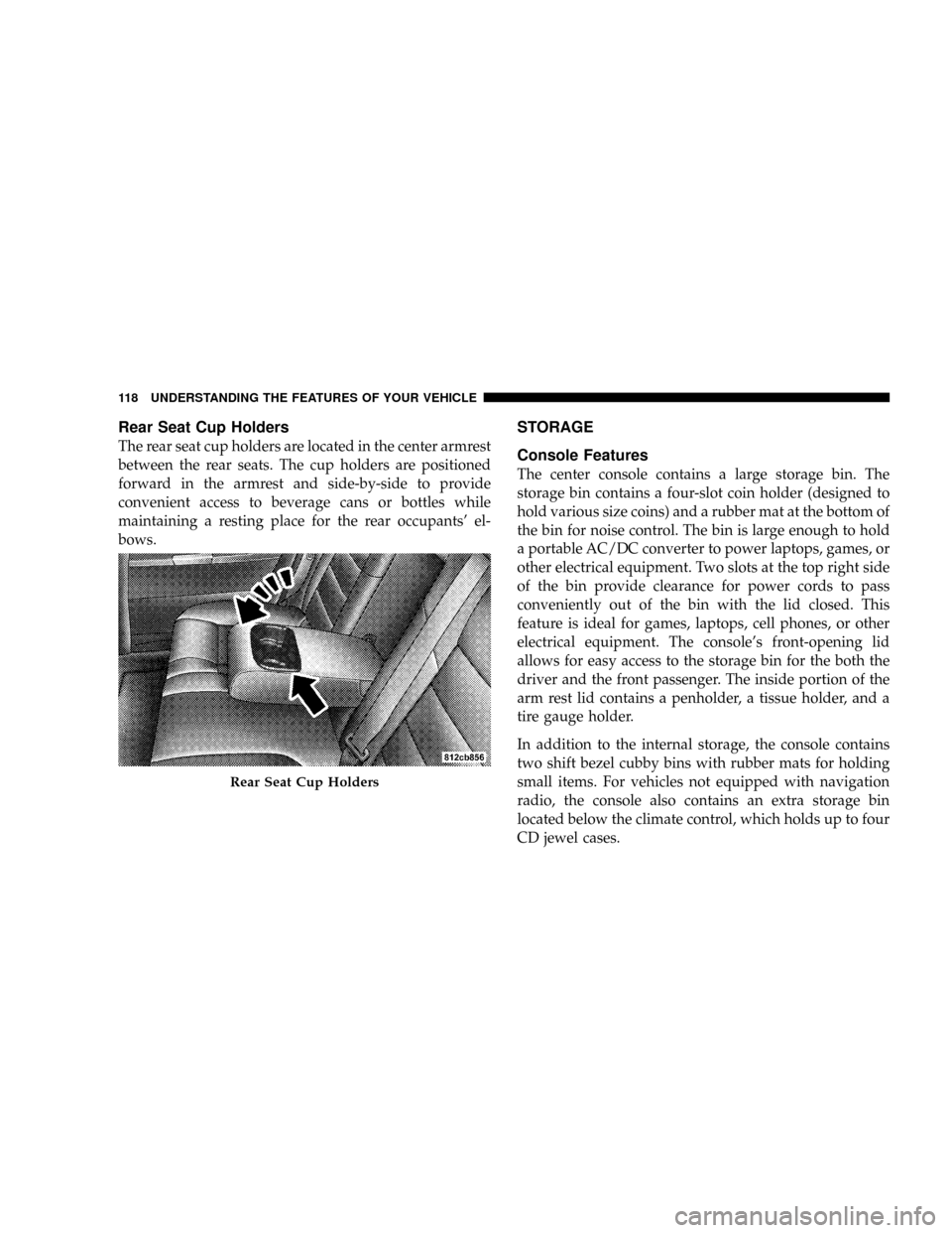
Rear Seat Cup Holders
The rear seat cup holders are located in the center armrest
between the rear seats. The cup holders are positioned
forward in the armrest and side-by-side to provide
convenient access to beverage cans or bottles while
maintaining a resting place for the rear occupants' el-
bows.
STORAGE
Console Features
The center console contains a large storage bin. The
storage bin contains a four-slot coin holder (designed to
hold various size coins) and a rubber mat at the bottom of
the bin for noise control. The bin is large enough to hold
a portable AC/DC converter to power laptops, games, or
other electrical equipment. Two slots at the top right side
of the bin provide clearance for power cords to pass
conveniently out of the bin with the lid closed. This
feature is ideal for games, laptops, cell phones, or other
electrical equipment. The console's front-opening lid
allows for easy access to the storage bin for the both the
driver and the front passenger. The inside portion of the
arm rest lid contains a penholder, a tissue holder, and a
tire gauge holder.
In addition to the internal storage, the console contains
two shift bezel cubby bins with rubber mats for holding
small items. For vehicles not equipped with navigation
radio, the console also contains an extra storage bin
located below the climate control, which holds up to four
CD jewel cases.
Rear Seat Cup Holders
118 UNDERSTANDING THE FEATURES OF YOUR VEHICLE
Page 141 of 380
turn on in the event of an EBD failure. Immediate repair
of the ABS system is required in the event of an EBD
failure.
The operation of the Brake Warning Light can be checked
by turning the ignition switch from the OFF position to
the ON position. The light should turn on for approxi-
mately two seconds and then turn off. The light will
remain on if the parking brake is applied or if a brake
fault is detected. If the parking brake is not applied and
the light remains on, or if the light does not turn on, have
the light inspected by an authorized dealer.
NOTE:The light will turn on when the ignition switch
in the ON position and the parking brake is applied. This
light shows only that the parking brake is applied. It does
not show the degree of brake application. (See page 219
for more information.)
21. Vehicle Security Alarm (VSA) Indicator Light Ð
If Equipped
The VSA indicator Light flashes rapidly when the VSA is
arming, and slowly when the VSA is armed. (See page 15
for more information.)
22. Tire Pressure Monitoring Telltale Light Ð If
Equipped
Each tire, including the spare (if provided),
should be checked monthly when cold and
inflated to the inflation pressure recom-
mended by the vehicle manufacturer on the
vehicle placard or tire inflation pressure label. (If your
vehicle has tires of a different size than the size
indicated on the vehicle placard or tire inflation pres-
sure label, you should determine the proper tire
inflation pressure for those tires.)
As an added safety feature, your vehicle has been
equipped with a tire pressure monitoring system (TPMS)
that illuminates a low tire pressure telltale when one or
more of your tires are significantly under-inflated. Ac-
cordingly, when the low tire pressure telltale illuminates,
you should stop and check your tires as soon as possible,
and inflate them to the proper pressure. Driving on a
significantly under-inflated tire causes the tire to over-
heat and can lead to tire failure. Under-inflation also
reduces fuel efficiency and tire tread life, and may affect
the vehicle's handling and stopping ability.
140 UNDERSTANDING YOUR INSTRUMENT PANEL
Page 142 of 380
Please note that the TPMS is not a substitute for proper
tire maintenance, and it is the driver 's responsibility to
maintain correct tire pressure, even if under-inflation has
not reached the level to trigger illumination of the TPMS
low tire pressure telltale.
The Tire Pressure Monitoring Telltale Light will illumi-
nate in the instrument cluster, and an audible chime will
be activated when one or more tire pressures is low. The
Tire Pressure Monitoring Telltale Light will flash on and
off for 60 seconds when a system fault is detected. The
flash cycle will repeat every ten minutes or until the fault
condition is removed and reset. (See page 246 for more
information.)CAUTION!
The TPMS has been optimized for the original
equipment tires and wheels. TPMS pressures and
warning have been established for the tire size
equipped on your vehicle. Undesirable system op-
eration or sensor damage may result when using
replacement equipment that is not of the same size,
type, and/or style. After-market wheels can cause
sensor damage. Do not use tire sealant from a can, or
balance beads if your vehicle is equipped with a
TPMS, as damage to the sensors may result.
UNDERSTANDING YOUR INSTRUMENT PANEL 141
4
Page 222 of 380
All vehicle wheels and tires must be the same size and
type and tires must be properly inflated to produce
accurate signals for the computer.
Anti-Lock Brake Light
The ABS light monitors the Anti-Lock Brake Sys-
tem. The light will come on when the ignition
switch is turned to the ON position and may stay on for
as long as four seconds.
If the ABS light remains on or comes on while driving, it
indicates that the Anti-Lock portion of the brake system
is not functioning and that service is required. However,
the conventional brake system will continue to operate
normally if the BRAKE warning light is not on.
If the ABS light is on, the brake system should be serviced
as soon as possible to restore the benefits of Anti-Lock
brakes. If the ABS light does not come on when the
Ignition switch is turned to the ON position, have the
bulb repaired as soon as possible.
If both the Brake Warning Light and the ABS Light
remain on, the Anti-Lock brakes (ABS) and ElectronicBrake Force Distribution (EBD) systems are not function-
ing. Immediate repair to the ABS system is required.
POWER STEERING
The standard power steering system will give you good
vehicle response and increased ease of maneuverability
in tight spaces. The system will provide mechanical
steering capability if power assist is lost.
If for some reason the power assist is interrupted, it will
still be possible to steer your vehicle. Under these condi-
tions, you will observe a substantial increase in steering
effort, especially at very low vehicle speeds and during
parking maneuvers.
NOTE:Increased noise levels at the end of the steering
wheel travel are considered normal and do not indicate
that there is a problem with the power steering system.
Upon initial start-up in cold weather, the power
steering pump may make noise for a short amount of
time. This is due to the cold, thick fluid in the steering
system. This noise should be considered normal, and
does not in any way damage the steering system.
STARTING AND OPERATING 221
5
Page 230 of 380
NOTE:
²
P (Passenger)-Metric tire sizing is based on U.S. design
standards. P-Metric tires have the letter ªPº molded
into the sidewall preceding the size designation. Ex-
ample: P215/65R15 95H.
²European Metric tire sizing is based on European
design standards. Tires designed to this standard have
the tire size molded into the sidewall beginning with
the section width. The letter9P9is absent from this tire
size designation. Example: 215/65R15 96H
²LT (Light Truck)-Metric tire sizing is based on U.S.
design standards. The size designation for LT-Metric
tires is the same as for P-Metric tires except for the
letters ªLTº that are molded into the sidewall preced-
ing the size designation. Example: LT235/85R16.
²Temporary Spare tires are high-pressure compact
spares designed for temporary emergency use only.
Tires designed to this standard have the letter ªTº
molded into the sidewall preceding the size designa-
tion. Example: T145/80D18 103M.
²High Flotation tire sizing is based on U.S. design
standards and it begins with the tire diameter molded
into the sidewall. Example: 31x10.5 R15 LT.
STARTING AND OPERATING 229
5
Page 231 of 380
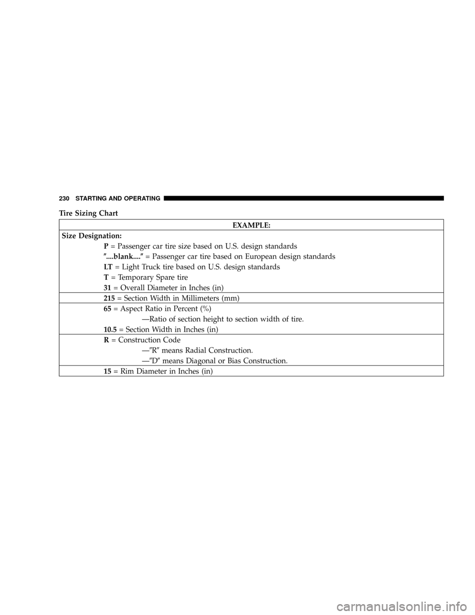
Tire Sizing Chart
EXAMPLE:
Size Designation:
P= Passenger car tire size based on U.S. design standards
(....blank....(= Passenger car tire based on European design standards
LT= Light Truck tire based on U.S. design standards
T= Temporary Spare tire
31= Overall Diameter in Inches (in)
215= Section Width in Millimeters (mm)
65= Aspect Ratio in Percent (%)
ÐRatio of section height to section width of tire.
10.5= Section Width in Inches (in)
R= Construction Code
Ð9R9means Radial Construction.
Ð9D9means Diagonal or Bias Construction.
15= Rim Diameter in Inches (in)
230 STARTING AND OPERATING
Page 233 of 380
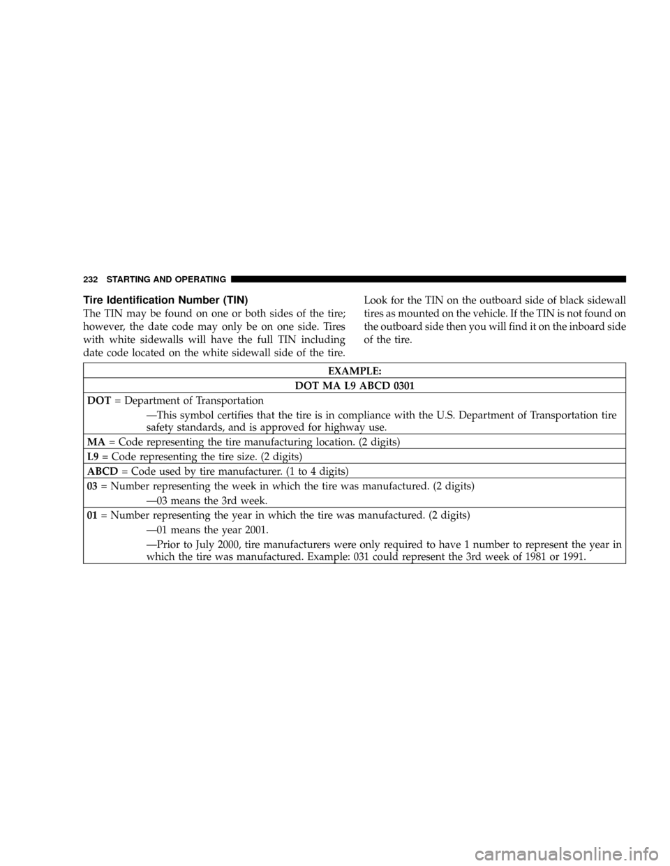
Tire Identification Number (TIN)
The TIN may be found on one or both sides of the tire;
however, the date code may only be on one side. Tires
with white sidewalls will have the full TIN including
date code located on the white sidewall side of the tire.Look for the TIN on the outboard side of black sidewall
tires as mounted on the vehicle. If the TIN is not found on
the outboard side then you will find it on the inboard side
of the tire.
EXAMPLE:
DOT MA L9 ABCD 0301
DOT= Department of Transportation
ÐThis symbol certifies that the tire is in compliance with the U.S. Department of Transportation tire
safety standards, and is approved for highway use.
MA= Code representing the tire manufacturing location. (2 digits)
L9= Code representing the tire size. (2 digits)
ABCD= Code used by tire manufacturer. (1 to 4 digits)
03= Number representing the week in which the tire was manufactured. (2 digits)
Ð03 means the 3rd week.
01= Number representing the year in which the tire was manufactured. (2 digits)
Ð01 means the year 2001.
ÐPrior to July 2000, tire manufacturers were only required to have 1 number to represent the year in
which the tire was manufactured. Example: 031 could represent the 3rd week of 1981 or 1991.
232 STARTING AND OPERATING
Page 234 of 380
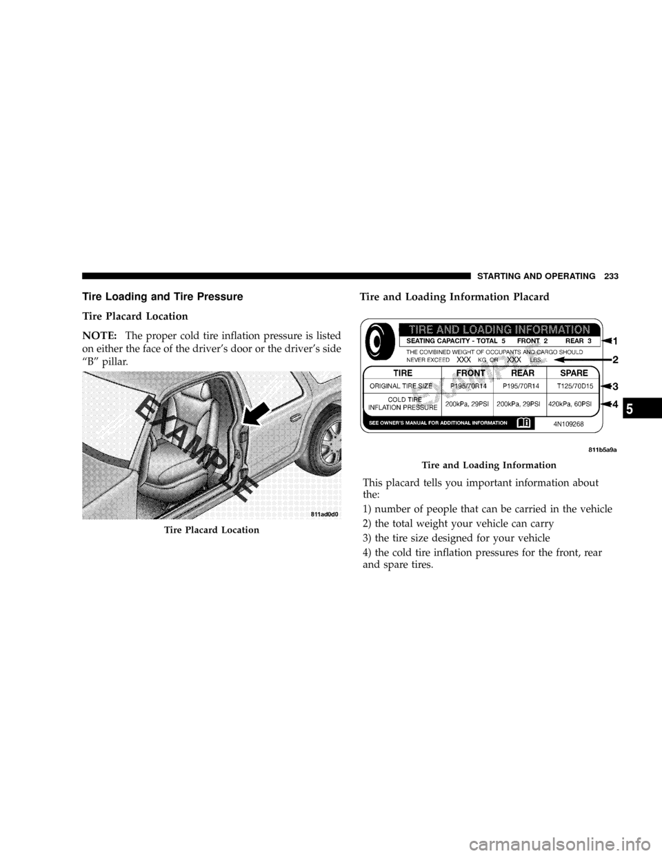
Tire Loading and Tire Pressure
Tire Placard Location
NOTE:
The proper cold tire inflation pressure is listed
on either the face of the driver's door or the driver's side
ªBº pillar.
Tire and Loading Information Placard
This placard tells you important information about
the:
1) number of people that can be carried in the vehicle
2) the total weight your vehicle can carry
3) the tire size designed for your vehicle
4) the cold tire inflation pressures for the front, rear
and spare tires.
Tire Placard Location
Tire and Loading Information
STARTING AND OPERATING 233
5
Page 235 of 380
Loading
The vehicle maximum load on the tire must not exceed
the load carrying capacity of the tire on your vehicle. You
will not exceed the tire's load carrying capacity if you
adhere to the loading conditions, tire size, and cold tire
inflation pressures specified on the ªTire and Loading
Informationº placard and in the ªVehicle Loadingº sec-
tion of this manual.
NOTE:Under a maximum loaded vehicle condition,
gross axle weight ratings (GAWR's) for the front and rear
axles must not be exceeded. For further information on
GAWR's, vehicle loading, and trailer towing, refer to the
ªVehicle Loadingº section of this manual.
To determine the maximum loading conditions of your
vehicle, locate the statement ªThe combined weight of
occupants and cargo should never exceed XXX kg or XXX
lbs.º on the Tire and Loading Information placard. The
combined weight of occupants, cargo/luggage and
trailer tongue weight (if applicable) should never exceed
the weight referenced here.
Steps for Determining Correct Load Limit
1. Locate the statement ªThe combined weight of occu-
pants and cargo should never exceed XXX poundsº on
your vehicle's placard.
2. Determine the combined weight of the driver and
passengers that will be riding in your vehicle.
3. Subtract the combined weight of the driver and pas-
sengers from XXX kilograms or XXX pounds.
4. The resulting figure equals the available amount of
cargo and luggage load capacity. For example, if ªXXXº
amount equals 1400 lbs. and there will be five 150 lb.
passengers in your vehicle, the amount of available cargo
and luggage load capacity is 650 lbs. (since 5 x 150 = 750,
and 1400 ± 750 = 650 lbs.)
5. Determine the combined weight of luggage and cargo
being loaded on the vehicle. That weight may not safely
exceed the available cargo and luggage load capacity
calculated in Step 4.
234 STARTING AND OPERATING