weight DODGE MAGNUM SRT 2007 1.G Owners Manual
[x] Cancel search | Manufacturer: DODGE, Model Year: 2007, Model line: MAGNUM SRT, Model: DODGE MAGNUM SRT 2007 1.GPages: 380, PDF Size: 6.63 MB
Page 50 of 380
WARNING!
In a collision, an unrestrained child, even a tiny
baby, can become a missile inside the vehicle. The
force required to hold even an infant on your lap
could become so great that you could not hold the
child, no matter how strong you are. The child and
others could be badly injured. Any child riding in
your vehicle should be in a proper restraint for the
child's size.
There are different sizes and types of restraints for
children from newborn size to the child almost large
enough for an adult safety belt. Always check the child
seat Owner's Manual to ensure you have the correct seat
for your child. Use the restraint that is correct for your
child:
Infants and Child Restraints
²
Safety experts recommend that children ride
rearward-facing in the vehicle until they are at leastone year oldandweigh at least 20 lbs (9 kg). Two types
of child restraints can be used rearward-facing: infant
carriers and ªconvertibleº child seats.
²The infant carrier is only used rearward-facing in the
vehicle. It is recommended for children who weigh up
to about 20 lbs (9 kg). ªConvertibleº child seats can be
used either rearward-facing or forward-facing in the
vehicle. Convertible child seats often have a higher
weight limit in the rearward-facing direction than
infant carriers do, so they can be used rearward-facing
by children who weigh more than 20 lbs (9 kg) but are
less than one year old. Both types of child restraints are
held in the vehicle by the lap/shoulder belt or the
LATCH child restraint anchorage system. Refer to
ªLATCH Ð Child Seat Anchorage System (Lower
Anchors and Tether for CHildren)º in this section.
²Rearward-facing child seats mustNEVERbe used in
the front seat of a vehicle with the front passenger
airbag unless the airbag is turned off. An airbag
deployment could cause severe injury or death to
infants in this position.
THINGS TO KNOW BEFORE STARTING YOUR VEHICLE 49
2
Page 52 of 380
WARNING!
²Improper installation can lead to failure of an
infant or child restraint. It could come loose in a
collision. The child could be badly injured or
killed. Follow the manufacturer's directions ex-
actly when installing an infant or child restraint.
²A rearward facing child restraint should only be
used in a rear seat. A rearward facing child re-
straint in the front seat may be struck by a
deploying passenger airbag, which may cause
severe or fatal injury to the infant.
Here are some tips on getting the most out of your child
restraint:
²Before buying any restraint system, make sure that it
has a label certifying that it meets all applicable Safety
Standards. We also recommend that you make sure
that you can install the child restraint in the vehicle
where you will use it before you buy it.
²The restraint must be appropriate for your child's
weight and height. Check the label on the restraint for
weight and height limits.
²Carefully follow the instructions that come with the
restraint. If you install the restraint improperly, it may
not work when you need it.
²Buckle the child into the seat according to the child
restraint manufacturer's directions.
²When your child restraint is not in use, secure it in the
vehicle with the seat belt or remove it from the vehicle.
Do not leave it loose in the vehicle. In a sudden stop or
collision, it could strike the occupants or seat backs
and cause serious personal injury.
LATCH Ð Child Seat Anchorage System (Lower
Anchors and Tether for CH ildren)
Your vehicle's rear seat is equipped with the child
restraint anchorage system called LATCH. The LATCH
system provides for the installation of the child restraint
without using the vehicle's seat belts, instead securing
THINGS TO KNOW BEFORE STARTING YOUR VEHICLE 51
2
Page 120 of 380
Cargo Management System Ð If Equipped
The cargo area has an upper and lower load floor.
Additional innovative features in the cargo area are the
two molded-in bins in the quarter trim panels. Each bin
will hold a gallon of milk and a 2-liter bottle of pop.
A cargo management system that stores on the lower
load floor below the bi-level cargo floor is optional. It
includes the following equipment:
²Waterproof cargo floor liner.
²Folding cargo management container with net separa-
tors.
The bi-level cargo floor includes a removable, tri-fold
load-bearing upper level. Two folds in the panel allow it
to be partially or fully folded for storage flexibility.
Shallow items can be stored underneath the upper load
floor.
The lower load floor is hinged to provide access to the
spare tire (if equipped), battery, and rear electrical power
distribution center.The 60/40 split-folding rear seat provides cargo-carrying
versatility. The seatbacks fold down easily by pulling
nylon tabs between the seatbacks and the bolsters. When
the seats are folded down, they provide a continuous,
nearly flat extension of the removable tri-fold load floor.
Tri-Fold Upper Load Floor
The removable tri-fold upper load floor has two different
surfaces for increased utility. One side is carpeted for a
plush appearance and the other side is covered with
vinyl for easy cleaning. The panel, sandwiched between
the carpet and the washable-vinyl, is constructed from a
strong lightweight material that gives the floor its load-
bearing strength.
You can place the load floor in a partially folded position,
a fully folded position, or a flat position. You can also
remove it from the vehicle. Folding and/or removing the
load floor will add four inches to the height of the cargo
area for increased utility. Use the handle to adjust the
position of the load floor. The load floor positions are
shown in the following illustrations.
UNDERSTANDING THE FEATURES OF YOUR VEHICLE 119
3
Page 126 of 380
Cargo Tie-Down Hooks
The tie-downs located on cargo area floor and on the rear
trim panels should be used to safely secure loads when
vehicle is moving.
WARNING!
²Cargo tie-down hooks are not safe anchors for a
child seat tether strap. In a sudden stop or colli-
sion, a hook could pull loose and allow the child
seat to come loose. A child could be badly injured.
Use only the anchors provided for child seat
tethers.
²The weight and position of cargo and passengers
can change the vehicle center of gravity and
vehicle handling. To avoid loss of control result-
ing in personal injury, follow these guidelines for
loading your vehicle:
²Always place cargo evenly on the cargo floor. Put
heavier objects as low and as far forward as possible.
²Place as much cargo as possible in front of the rear
axle. Too much weight or improperly placed weight
over or behind the rear axle can cause the rear of the
vehicle to sway.
²Do not pile luggage or cargo higher than the top of the
seatback. This could impair visibility or become a
dangerous projectile in a sudden stop or collision.
WARNING!
To help protect against personal injury, passengers
should not be seated in the rear cargo area. The rear
cargo space is intended for load carrying purposes
only, not for passengers, who should sit in seats and
use seat belts.
UNDERSTANDING THE FEATURES OF YOUR VEHICLE 125
3
Page 127 of 380
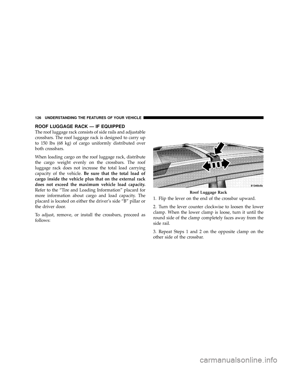
ROOF LUGGAGE RACK Ð IF EQUIPPED
The roof luggage rack consists of side rails and adjustable
crossbars. The roof luggage rack is designed to carry up
to 150 lbs (68 kg) of cargo uniformly distributed over
both crossbars.
When loading cargo on the roof luggage rack, distribute
the cargo weight evenly on the crossbars. The roof
luggage rack does not increase the total load carrying
capacity of the vehicle.Be sure that the total load of
cargo inside the vehicle plus that on the external rack
does not exceed the maximum vehicle load capacity.
Refer to the ªTire and Loading Informationº placard for
more information about cargo and load capacity. The
placard is located on either the driver's side ªBº pillar or
the driver door.
To adjust, remove, or install the crossbars, proceed as
follows:1. Flip the lever on the end of the crossbar upward.
2. Turn the lever counter clockwise to loosen the lower
clamp. When the lower clamp is loose, turn it until the
round side of the clamp completely faces away from the
side rail.
3. Repeat Steps 1 and 2 on the opposite clamp on the
other side of the crossbar.
Roof Luggage Rack
126 UNDERSTANDING THE FEATURES OF YOUR VEHICLE
Page 147 of 380
²Elapsed Time
²Display Units of Measure in
Press the SCROLL button to cycle through all the Trip
Computer functions.
The Trip Functions mode displays the following:
²Average Fuel Economy
Shows the average fuel economy since the last reset.
When the fuel economy is reset, the display will read
ªRESETº or show dashes for two seconds. Then, the
history information will be erased, and the averaging will
continue from the last fuel average reading before the
reset.
²Distance To Empty (DTE)
Shows the estimated distance that can be traveled with
the fuel remaining in the tank. This estimated distance is
determined by a weighted average of the instantaneous
and average fuel economy, according to the current fuel
tank level. DTE cannot be reset through the FUNCTION
SELECT button.
NOTE:Significant changes in driving style or vehicle
loading will greatly affect the actual drivable distance of
the vehicle, regardless of the DTE displayed value.
²When the DTE value is less than 30 miles (48 km)
estimated driving distance, the DTE display will
change to a text display of9LOW FUEL.9This display
will continue until the vehicle runs out of fuel. Adding
a significant amount of fuel to the vehicle will turn off
the9LOW FUEL9text and a new DTE value will
display.
²Trip A
Shows the total distance traveled for trip A since the last
reset.
²Trip B
Shows the total distance traveled for trip B since the last
reset.
²Elapsed Time
Shows the total elapsed time of travel since the last reset
when the ignition switch is in the ACC position. Elapsed
time will increment when the ignition switch is in the ON
or START position.
146 UNDERSTANDING YOUR INSTRUMENT PANEL
Page 204 of 380
N6.1L Engine.........................253
NReformulated Gasoline.................254
NGasoline/Oxygenate Blends..............254
NMMT In Gasoline.....................255
NMaterials Added To Fuel................255
NFuel System Cautions..................255
NCarbon Monoxide Warnings..............256
mAdding Fuel..........................257
NFuel Filler Cap (Gas Cap)...............257
NLoose Fuel Filler Cap Message............259
mVehicle Loading.......................259
NVehicle Certification Label...............259
NGross Vehicle Weight Rating (GVWR).......260
NGross Axle Weight Rating (GAWR).........260
NOverloading.........................260NLoading............................261
mTrailer Towing........................262
NCommon Towing Definitions.............262
NTrailer Hitch Classification...............265
NTrailer Towing Weights (Maximum Trailer
Weight Ratings)......................265
NTrailer And Tongue Weight..............266
NTowing Requirements..................267
NTowing Tips.........................271
mRecreational Towing
(Behind Motorhome, Etc.)
................273
NTowing This Vehicle Behind Another Vehicle
(Flat Towing With All Four Wheels On The
Ground)............................273
mGround Clearance.....................273
STARTING AND OPERATING 203
5
Page 234 of 380
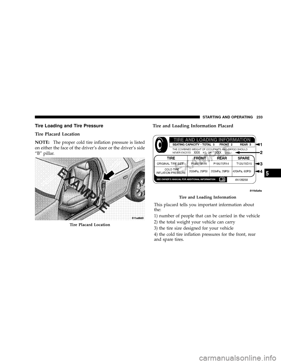
Tire Loading and Tire Pressure
Tire Placard Location
NOTE:
The proper cold tire inflation pressure is listed
on either the face of the driver's door or the driver's side
ªBº pillar.
Tire and Loading Information Placard
This placard tells you important information about
the:
1) number of people that can be carried in the vehicle
2) the total weight your vehicle can carry
3) the tire size designed for your vehicle
4) the cold tire inflation pressures for the front, rear
and spare tires.
Tire Placard Location
Tire and Loading Information
STARTING AND OPERATING 233
5
Page 235 of 380
Loading
The vehicle maximum load on the tire must not exceed
the load carrying capacity of the tire on your vehicle. You
will not exceed the tire's load carrying capacity if you
adhere to the loading conditions, tire size, and cold tire
inflation pressures specified on the ªTire and Loading
Informationº placard and in the ªVehicle Loadingº sec-
tion of this manual.
NOTE:Under a maximum loaded vehicle condition,
gross axle weight ratings (GAWR's) for the front and rear
axles must not be exceeded. For further information on
GAWR's, vehicle loading, and trailer towing, refer to the
ªVehicle Loadingº section of this manual.
To determine the maximum loading conditions of your
vehicle, locate the statement ªThe combined weight of
occupants and cargo should never exceed XXX kg or XXX
lbs.º on the Tire and Loading Information placard. The
combined weight of occupants, cargo/luggage and
trailer tongue weight (if applicable) should never exceed
the weight referenced here.
Steps for Determining Correct Load Limit
1. Locate the statement ªThe combined weight of occu-
pants and cargo should never exceed XXX poundsº on
your vehicle's placard.
2. Determine the combined weight of the driver and
passengers that will be riding in your vehicle.
3. Subtract the combined weight of the driver and pas-
sengers from XXX kilograms or XXX pounds.
4. The resulting figure equals the available amount of
cargo and luggage load capacity. For example, if ªXXXº
amount equals 1400 lbs. and there will be five 150 lb.
passengers in your vehicle, the amount of available cargo
and luggage load capacity is 650 lbs. (since 5 x 150 = 750,
and 1400 ± 750 = 650 lbs.)
5. Determine the combined weight of luggage and cargo
being loaded on the vehicle. That weight may not safely
exceed the available cargo and luggage load capacity
calculated in Step 4.
234 STARTING AND OPERATING
Page 236 of 380
6. If your vehicle will be towing a trailer, load from your
trailer will be transferred to your vehicle. Consult this
manual to determine how this reduces the available
cargo and luggage load capacity of your vehicle.
NOTE:The following table shows examples on how to
calculate total load, cargo/luggage, and towing capaci-
ties of your vehicle with varying seating configurationsand number and size of occupants. This table is for
illustration purposes only and may not be accurate for
the seating and load carry capacity of your vehicle.
NOTE:For the following example, the combined
weight of occupants and cargo should never exceed 865
lbs. (392 Kg).
STARTING AND OPERATING 235
5