brake DODGE NEON 1999 Service Owner's Manual
[x] Cancel search | Manufacturer: DODGE, Model Year: 1999, Model line: NEON, Model: DODGE NEON 1999Pages: 1200, PDF Size: 35.29 MB
Page 58 of 1200
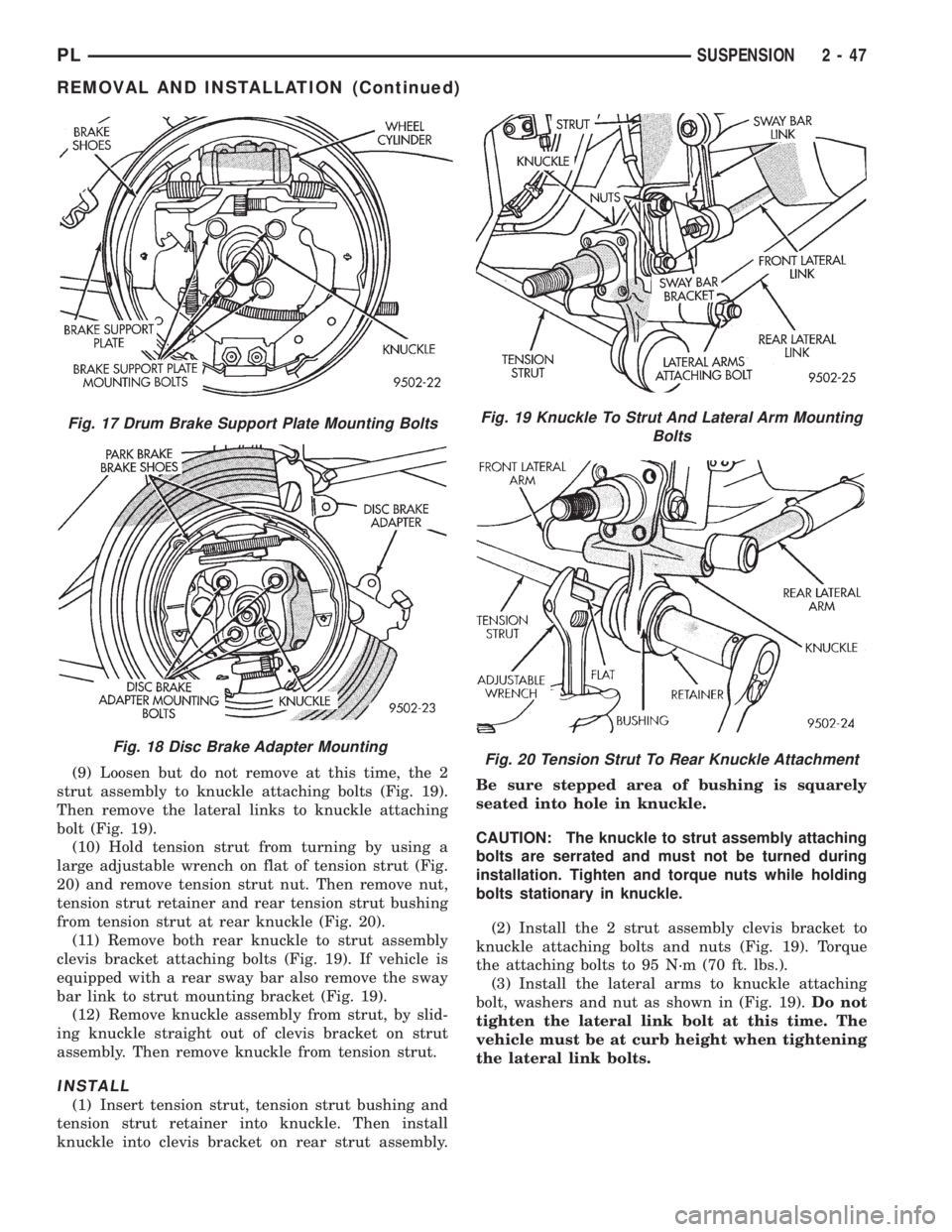
(9) Loosen but do not remove at this time, the 2
strut assembly to knuckle attaching bolts (Fig. 19).
Then remove the lateral links to knuckle attaching
bolt (Fig. 19).
(10) Hold tension strut from turning by using a
large adjustable wrench on flat of tension strut (Fig.
20) and remove tension strut nut. Then remove nut,
tension strut retainer and rear tension strut bushing
from tension strut at rear knuckle (Fig. 20).
(11) Remove both rear knuckle to strut assembly
clevis bracket attaching bolts (Fig. 19). If vehicle is
equipped with a rear sway bar also remove the sway
bar link to strut mounting bracket (Fig. 19).
(12) Remove knuckle assembly from strut, by slid-
ing knuckle straight out of clevis bracket on strut
assembly. Then remove knuckle from tension strut.
INSTALL
(1) Insert tension strut, tension strut bushing and
tension strut retainer into knuckle. Then install
knuckle into clevis bracket on rear strut assembly.Be sure stepped area of bushing is squarely
seated into hole in knuckle.
CAUTION: The knuckle to strut assembly attaching
bolts are serrated and must not be turned during
installation. Tighten and torque nuts while holding
bolts stationary in knuckle.
(2) Install the 2 strut assembly clevis bracket to
knuckle attaching bolts and nuts (Fig. 19). Torque
the attaching bolts to 95 N´m (70 ft. lbs.).
(3) Install the lateral arms to knuckle attaching
bolt, washers and nut as shown in (Fig. 19).Do not
tighten the lateral link bolt at this time. The
vehicle must be at curb height when tightening
the lateral link bolts.
Fig. 17 Drum Brake Support Plate Mounting Bolts
Fig. 18 Disc Brake Adapter Mounting
Fig. 19 Knuckle To Strut And Lateral Arm Mounting
Bolts
Fig. 20 Tension Strut To Rear Knuckle Attachment
PLSUSPENSION 2 - 47
REMOVAL AND INSTALLATION (Continued)
Page 59 of 1200
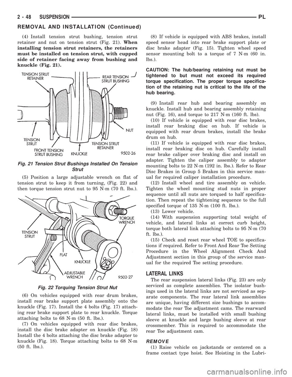
(4) Install tension strut bushing, tension strut
retainer and nut on tension strut (Fig. 21).When
installing tension strut retainers, the retainers
must be installed on tension strut, with cupped
side of retainer facing away from bushing and
knuckle (Fig. 21).
(5) Position a large adjustable wrench on flat of
tension strut to keep it from turning, (Fig. 22) and
then torque tension strut nut to 95 N´m (70 ft. lbs.).
(6) On vehicles equipped with rear drum brakes,
install rear brake support plate assembly onto the
knuckle (Fig. 17). Install the 4 bolts (Fig. 17) attach-
ing rear brake support plate to rear knuckle. Torque
attaching bolts to 68 N´m (50 ft. lbs.).
(7) On vehicles equipped with rear disc brakes,
install the disc brake adapter on knuckle (Fig. 18)
Install the 4 bolts attaching the disc brake adapter to
knuckle (Fig. 18). Torque attaching bolts to 68 N´m
(50 ft. lbs.).(8) If vehicle is equipped with ABS brakes, install
speed sensor head into rear brake support plate or
disc brake adapter (Fig. 15). Tighten wheel speed
sensor mounting bolt to a torque of 7 N´m (60 in.
lbs.).
CAUTION: The hub/bearing retaining nut must be
tightened to but must not exceed its required
torque specification. The proper torque specifica-
tion of the retaining nut is critical to the life of the
hub bearing.
(9) Install rear hub and bearing assembly on
knuckle. Install hub and bearing assembly retaining
nut (Fig. 16), and torque to 217 N´m (160 ft. lbs).
(10) If vehicle is equipped with rear disc brakes,
install rear braking disc on hub. If vehicle is
equipped with rear drum brakes, install the brake
drum on hub.
(11) If vehicle is equipped with rear disc brakes,
install rear braking disc on hub. Carefully install
rear brake caliper over braking disc and install on
adapter. Tighten the caliper assembly to adapter
mounting bolts to 22 N´m (192 in. lbs.). Refer to Rear
Disc Brakes in Group 5 Brakes in this service man-
ual for required caliper installation procedure.
(12) Install wheel and tire assembly on vehicle.
Tighten the wheel mounting stud nuts in proper
sequence until all nuts are torqued to half specifica-
tion. Then repeat the tightening sequence to the full
specified torque of 135 N´m (100 ft. lbs.).
(13) Lower vehicle.
(14) With suspension supporting total weight of
vehicle, and lateral links at correct curb height,
torque both lateral link attaching bolts to 95 N´m (70
ft. lbs.).
(15) Check and reset rear wheel TOE to specifica-
tions if required. Refer to Front And Rear Toe Setting
Procedure in the Wheel Alignment Check And
Adjustment section in this group of the service man-
ual for the required Toe setting procedure.
LATERAL LINKS
The rear suspension lateral links (Fig. 23) are only
serviced as complete assemblies. The isolator bush-
ings used in the lateral links are not serviced as sep-
arate components. The rear lateral link assemblies
are unique, having different size bushings to accom-
modate the rear Toe adjustment cams. The rearward
lateral links, must be installed with small bushing
sleeve at knuckle and large bushing sleeve at rear
crossmember. This is required to accommodate the
rear Toe adjustment cam.
REMOVE
(1) Raise vehicle on jackstands or centered on a
frame contact type hoist. See Hoisting in the Lubri-
Fig. 21 Tension Strut Bushings Installed On Tension
Strut
Fig. 22 Torquing Tension Strut Nut
2 - 48 SUSPENSIONPL
REMOVAL AND INSTALLATION (Continued)
Page 65 of 1200
SPECIFICATIONS
REAR SUSPENSION FASTENER TORQUE
SPECIFICATIONS
DESCRIPTION TORQUE
STRUT ASSEMBLY:
To Body Attaching Nuts.......34N´m(300 in. lbs.)
Clevis Bracket To Knuckle
Nut/Bolt..................95N´m(70ft.lbs.)
Strut Assembly Shaft Nut.......75N´m(55ft.lbs.)
BRAKE SUPPORT PLATE:
To Knuckle Bolts..............68N´m(50ft.lbs.)
STABILIZER BAR:
Bushing Retainer To
Frame Bolt...............34N´m(300 in. lbs.)
To Strut Attaching Link Nut . . .34 N´m (300 in. lbs.)
TENSION STRUT:
Shaft Nut...................95N´m(70ft.lbs.)
Bracket To Body Attaching
Bolts.....................95N´m(70ft.lbs.)
LATERAL LINK:
Attaching Nut................95N´m(70ft.lbs.)
DISC BRAKE CALIPER:
To Adapter Mounting Bolt......22N´m(16ft.lbs.)
Brake Hose To Caliper
Mounting Bolt..............45N´m(35ft.lbs.)
Adapter To Knuckle
Mounting Bolt..............68N´m(50ft.lbs.)
BRAKE HOSE:
Bracket Mounting Bolt........23N´m(17ft.lbs.)
HUB AND BEARING:
To Knuckle Retaining Nut.....216 N´m (160 ft. lbs.)
Wheel Stud Lug Nuts
(All Wheel Types). . . .109-150 N´m (80-110 ft. lbs.)
SPECIAL TOOLS
REAR SUSPENSION
Compressor Strut Coil Spring C-4838
2 - 54 SUSPENSIONPL
Page 67 of 1200
the jounce and rebound travel of the front suspen-
sion.
On vehicles equipped with ABS brakes, the outer
C/V joint is equipped with a tone wheel used to
determine vehicle speed for ABS brake operation.
The inner tripod joint of both driveshafts is splined
into the transaxle side gears. The inner tripod joints
are retained in the side gears of the transaxle using
a snap ring located in the stub shaft of the tripod
joint. The outer C/V joint has a stub shaft that is
splined into the wheel hub and retained by a hub nut
using a nut lock and cotter pin.
NOTE: This vehicle does not use a rubber±lip bear-
ing seal as on previous front±wheel±drive cars to
prevent contamination of the front wheel bearing.
On these vehicles, the face of the outer C/V joint
fits deeply into the steering knuckle, using a close
outer C/V joint±to±steering knuckle fit. This design
deters direct water splash on bearing seal while
allowing any water that gets in, to run out the bot-
tom of the steering knuckle bearing bore. It is
important to thoroughly clean the outer C/V joint
and the wheel bearing area in the steering knuckle
before it is assembled after servicing.
DIAGNOSIS AND TESTING
DRIVESHAFT DIAGNOSIS
VEHICLE INSPECTION
(1) Check for grease in the vicinity of the inboard
tripod joint and outboard C/V joint; this is a sign of
inner or outer joint seal boot or seal boot clamp dam-
age.
(2) A light film of grease may appear on the right
inner tripod joint seal boot; this is considered normal
and should not require replacement of the seal boot.
The right inner tripod joint seal boot is made of sili-
cone rubber; which will allow the weeping (sweating)
of the joint lubricant to pass through it while in oper-
ation.
NOISE AND/OR VIBRATION IN TURNS
A clicking noise and/or a vibration in turns could
be caused by one of the following conditions.
(1) Damaged outer C/V or inner tripod joint seal
boot or seal boot clamps. This will result in the loss
and/or contamination of the joint grease, resulting in
inadequate lubrication of the joint.
(2) Noise may also be caused by another compo-
nent of the vehicle coming in contact with the drive-
shafts.
CLUNKING NOISE DURING ACCELERATION
This noise may be a result of one of the following
conditions:
(1) A torn seal boot on the inner or outer joint of
the driveshaft assembly.
(2) A loose or missing clamp on the inner or outer
joint of the driveshaft assembly.
(3) A damaged or worn driveshaft C/V joint.
SHUDDER OR VIBRATION DURING
ACCELERATION
(1) A worn or damaged driveshaft inner tripod
joint.
(2) A sticking tripod joint spider assembly (inner
tripod joint only).
(3) Improper wheel alignment. See Wheel Align-
ment in this group for alignment checking and set-
ting procedures and specifications.
VIBRATION AT HIGHWAY SPEEDS
(1) Foreign material (mud, etc.) packed on the
backside of the wheel(s).
(2) Out of balance front tires or wheels. See Group
22, Wheels And Tires for the required balancing pro-
cedure.
(3) Improper tire and/or wheel runout. See Group
22, Wheels And Tires for the required runout check-
ing procedure.
REMOVAL AND INSTALLATION
FRONT DRIVESHAFTS
CAUTION: Boot sealing is vital to retain special
lubricants and to prevent foreign contaminants
from entering the C/V joint. Mishandling, such as
allowing the assemblies to dangle unsupported, or
pulling or pushing the ends can cut boots or dam-
age C/V joints. During removal and installation pro-
cedures, always support both ends of the driveshaft
to prevent damage.
REMOVAL
CAUTION: The driveshaft, when installed, acts as a
bolt and secures the front hub/bearing assembly. If
vehicle is to be supported or moved on its wheels
with a driveshaft removed, install a PROPER±SIZED
BOLT AND NUT through front hub. Tighten bolt and
nut to 203 N´m (150 ft. lbs.). This will ensure that
the hub bearing cannot loosen.
(1) Remove cotter pin, nut lock, and spring washer
(Fig. 2) from the end of the outer C/V joint stub axle.
(2) Loosen (but do not remove) stub axle±to±hub/
bearing retaining nut (Fig. 3). Loosen hub nut while
3 - 2 DIFFERENTIAL AND DRIVELINEPL
GENERAL INFORMATION (Continued)
Page 68 of 1200
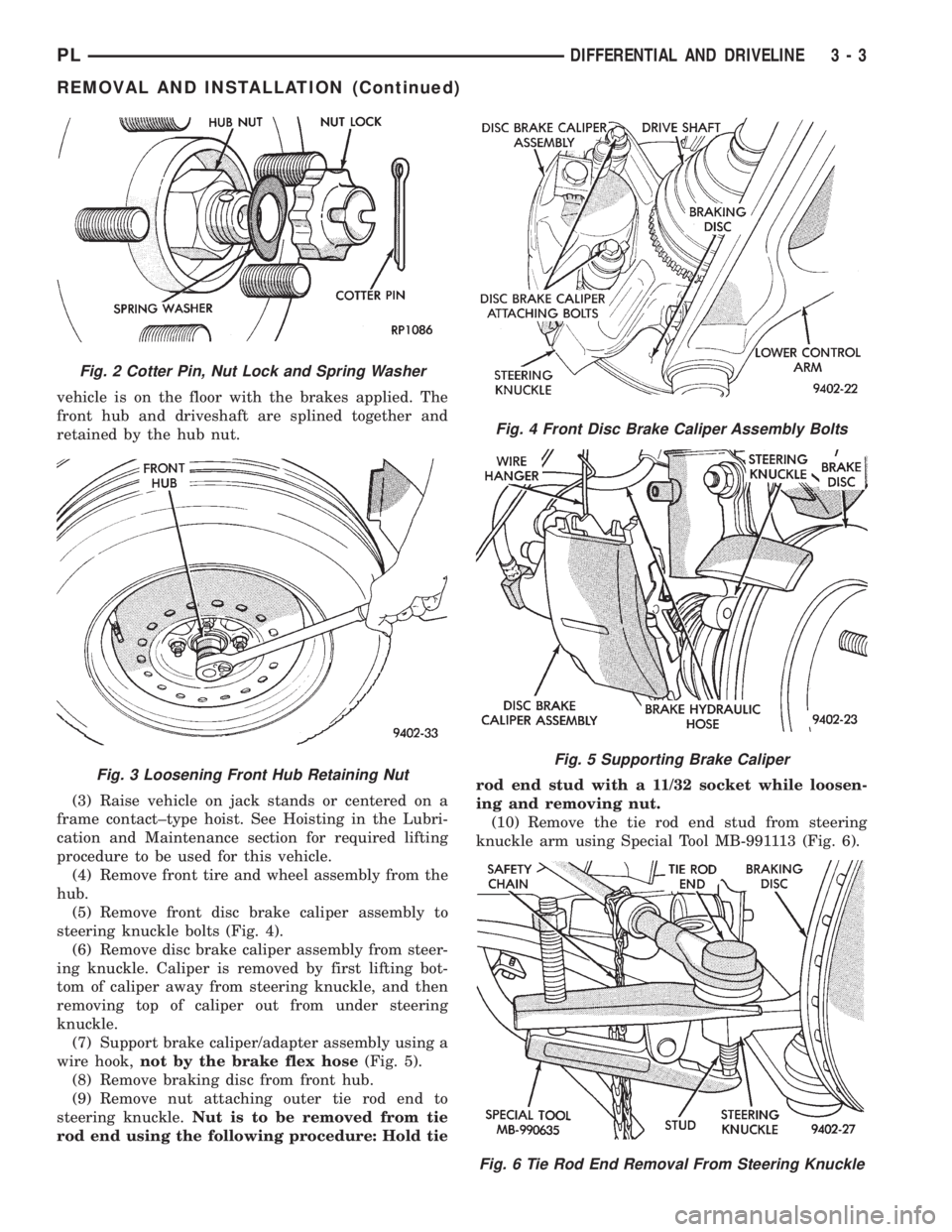
vehicle is on the floor with the brakes applied. The
front hub and driveshaft are splined together and
retained by the hub nut.
(3) Raise vehicle on jack stands or centered on a
frame contact±type hoist. See Hoisting in the Lubri-
cation and Maintenance section for required lifting
procedure to be used for this vehicle.
(4) Remove front tire and wheel assembly from the
hub.
(5) Remove front disc brake caliper assembly to
steering knuckle bolts (Fig. 4).
(6) Remove disc brake caliper assembly from steer-
ing knuckle. Caliper is removed by first lifting bot-
tom of caliper away from steering knuckle, and then
removing top of caliper out from under steering
knuckle.
(7) Support brake caliper/adapter assembly using a
wire hook,not by the brake flex hose(Fig. 5).
(8) Remove braking disc from front hub.
(9) Remove nut attaching outer tie rod end to
steering knuckle.Nut is to be removed from tie
rod end using the following procedure: Hold tierod end stud with a 11/32 socket while loosen-
ing and removing nut.
(10) Remove the tie rod end stud from steering
knuckle arm using Special Tool MB-991113 (Fig. 6).
Fig. 2 Cotter Pin, Nut Lock and Spring Washer
Fig. 3 Loosening Front Hub Retaining Nut
Fig. 4 Front Disc Brake Caliper Assembly Bolts
Fig. 5 Supporting Brake Caliper
Fig. 6 Tie Rod End Removal From Steering Knuckle
PLDIFFERENTIAL AND DRIVELINE 3 - 3
REMOVAL AND INSTALLATION (Continued)
Page 71 of 1200
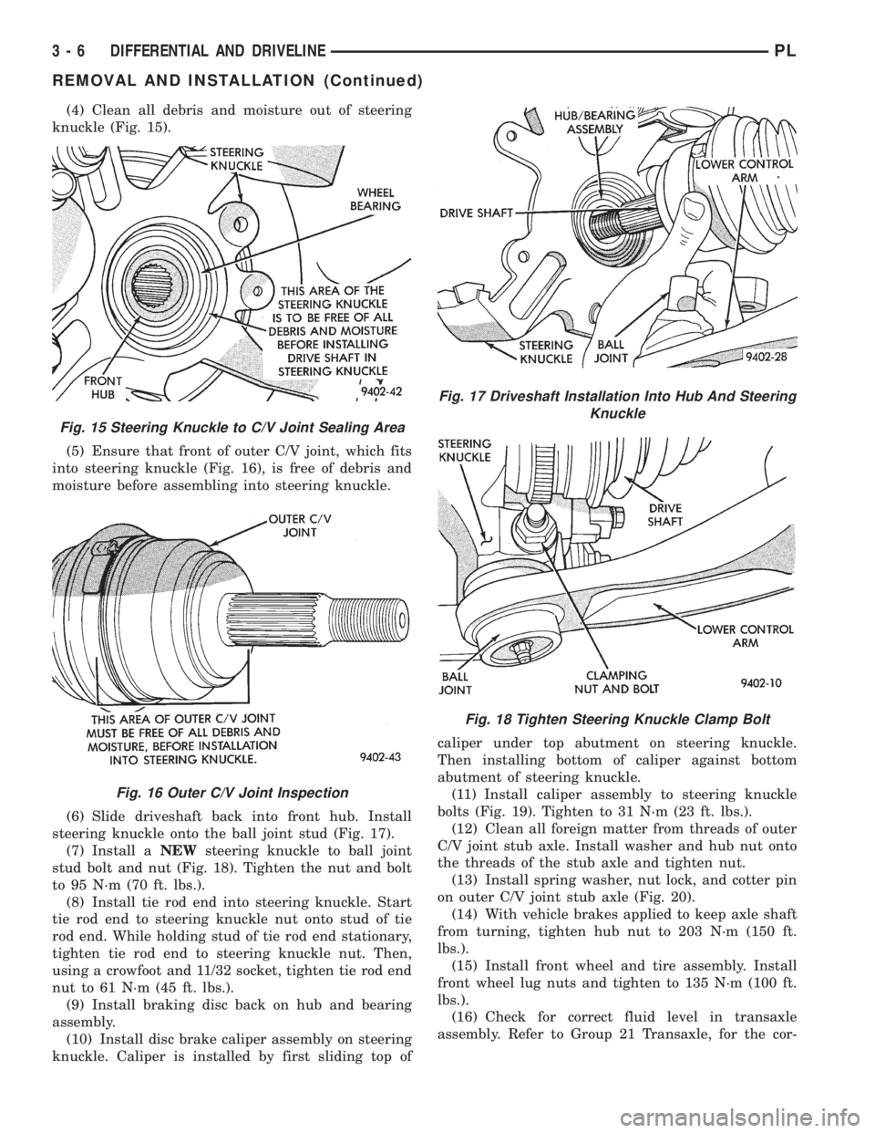
(4) Clean all debris and moisture out of steering
knuckle (Fig. 15).
(5) Ensure that front of outer C/V joint, which fits
into steering knuckle (Fig. 16), is free of debris and
moisture before assembling into steering knuckle.
(6) Slide driveshaft back into front hub. Install
steering knuckle onto the ball joint stud (Fig. 17).
(7) Install aNEWsteering knuckle to ball joint
stud bolt and nut (Fig. 18). Tighten the nut and bolt
to 95 N´m (70 ft. lbs.).
(8) Install tie rod end into steering knuckle. Start
tie rod end to steering knuckle nut onto stud of tie
rod end. While holding stud of tie rod end stationary,
tighten tie rod end to steering knuckle nut. Then,
using a crowfoot and 11/32 socket, tighten tie rod end
nut to 61 N´m (45 ft. lbs.).
(9) Install braking disc back on hub and bearing
assembly.
(10) Install disc brake caliper assembly on steering
knuckle. Caliper is installed by first sliding top ofcaliper under top abutment on steering knuckle.
Then installing bottom of caliper against bottom
abutment of steering knuckle.
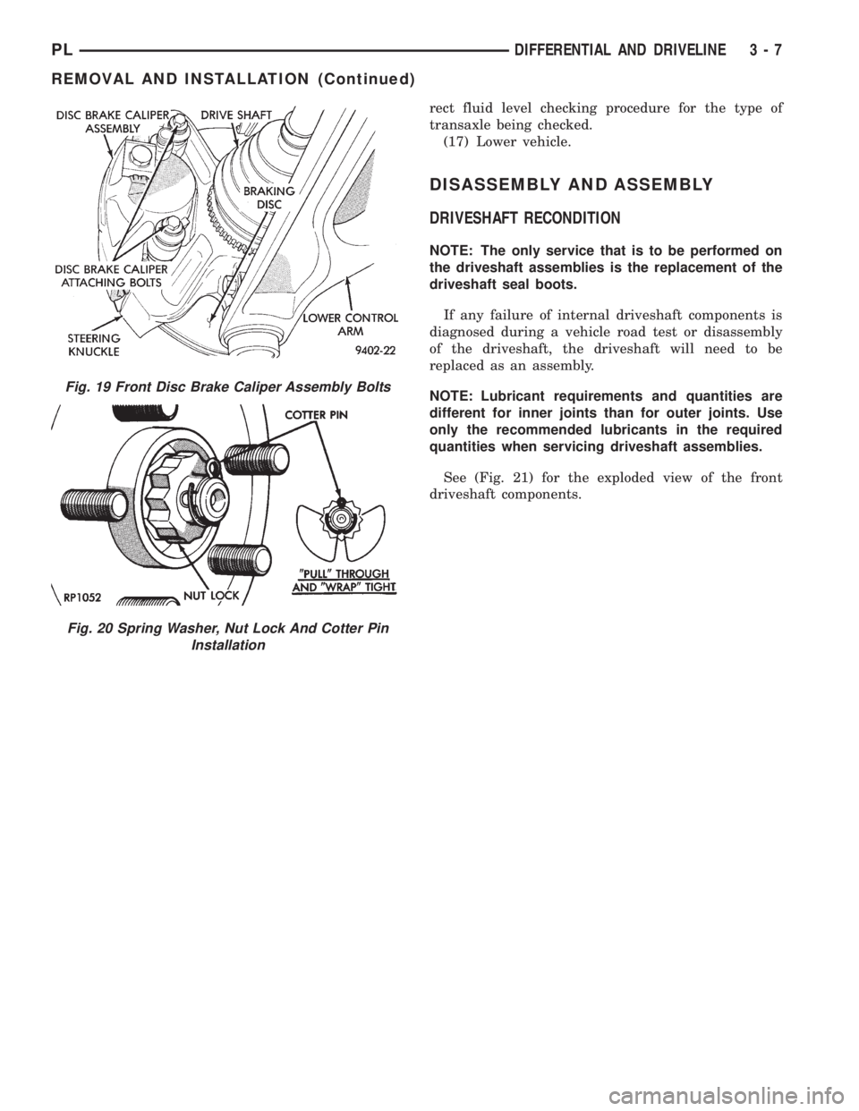
(11) Install caliper assembly to steering knuckle
bolts (Fig. 19). Tighten to 31 N´m (23 ft. lbs.).
(12) Clean all foreign matter from threads of outer
C/V joint stub axle. Install washer and hub nut onto
the threads of the stub axle and tighten nut.
(13) Install spring washer, nut lock, and cotter pin
on outer C/V joint stub axle (Fig. 20).
(14) With vehicle brakes applied to keep axle shaft
from turning, tighten hub nut to 203 N´m (150 ft.
lbs.).
(15) Install front wheel and tire assembly. Install
front wheel lug nuts and tighten to 135 N´m (100 ft.
lbs.).
(16) Check for correct fluid level in transaxle
assembly. Refer to Group 21 Transaxle, for the cor-
Fig. 15 Steering Knuckle to C/V Joint Sealing Area
Fig. 16 Outer C/V Joint Inspection
Fig. 17 Driveshaft Installation Into Hub And Steering
Knuckle
Fig. 18 Tighten Steering Knuckle Clamp Bolt
3 - 6 DIFFERENTIAL AND DRIVELINEPL
REMOVAL AND INSTALLATION (Continued)
Page 72 of 1200
rect fluid level checking procedure for the type of
transaxle being checked.
(17) Lower vehicle.
DISASSEMBLY AND ASSEMBLY
DRIVESHAFT RECONDITION
NOTE: The only service that is to be performed on
the driveshaft assemblies is the replacement of the
driveshaft seal boots.
If any failure of internal driveshaft components is
diagnosed during a vehicle road test or disassembly
of the driveshaft, the driveshaft will need to be
replaced as an assembly.
NOTE: Lubricant requirements and quantities are
different for inner joints than for outer joints. Use
only the recommended lubricants in the required
quantities when servicing driveshaft assemblies.
See (Fig. 21) for the exploded view of the front
driveshaft components.
Fig. 19 Front Disc Brake Caliper Assembly Bolts
Fig. 20 Spring Washer, Nut Lock And Cotter Pin
Installation
PLDIFFERENTIAL AND DRIVELINE 3 - 7
REMOVAL AND INSTALLATION (Continued)
Page 82 of 1200
BRAKES
CONTENTS
page page
ANTILOCK BRAKE SYSTEM±TEVES MARK 20 . 69
BASE BRAKE SYSTEM..................... 2GENERAL INFORMATION................... 1
GENERAL INFORMATION
INDEX
page
GENERAL INFORMATION
BASE BRAKE SYSTEM DESCRIPTION........ 1
GENERAL INFORMATION
BASE BRAKE SYSTEM DESCRIPTION
Typical brake equipment consists of:
²Double pin floating caliper disc front brakes.
²Rear automatic adjusting drum brakes.
²Brake Fluid Level Switch.
²Master cylinder.
²Vacuum power booster.
²Double pin floating caliper rear disc brakes are
available on some models.
²Hand operated auto adjust park brake lever.
²Front disc brake pads are semi-metallic.
Vehicles equipped with the optional antilock brake
system (ABS) use a system designated Mark 20 and
is supplied by Teves. This system shares the base
brake hardware with vehicles not equipped withABS. A vehicle equipped with ABS does however use
a different vacuum booster, master cylinder and
brake tubes. Also included in the ABS system is an
integrated control unit (ICU), four wheel speed sen-
sors, and an electronic controller referred to as the
controller antilock brakes (CAB). These components
will be described in detail in the Teves Mark 20 ABS
brake section in this group of the service manual.
The hydraulic brake system is diagonally split on
both the Non-ABS and ABS braking system. With the
left front and right rear brakes on one hydraulic sys-
tem and the right front and left rear on the other.
The master cylinder is anodized, lightweight alu-
minum. On vehicles equipped with front disc brakes
and rear drum brakes, the master cylinder bore is
21.0 mm. On vehicles equipped with four wheel disc
brakes, the master cylinder bore is 22.2 mm.
PLBRAKES 5 - 1
Page 83 of 1200
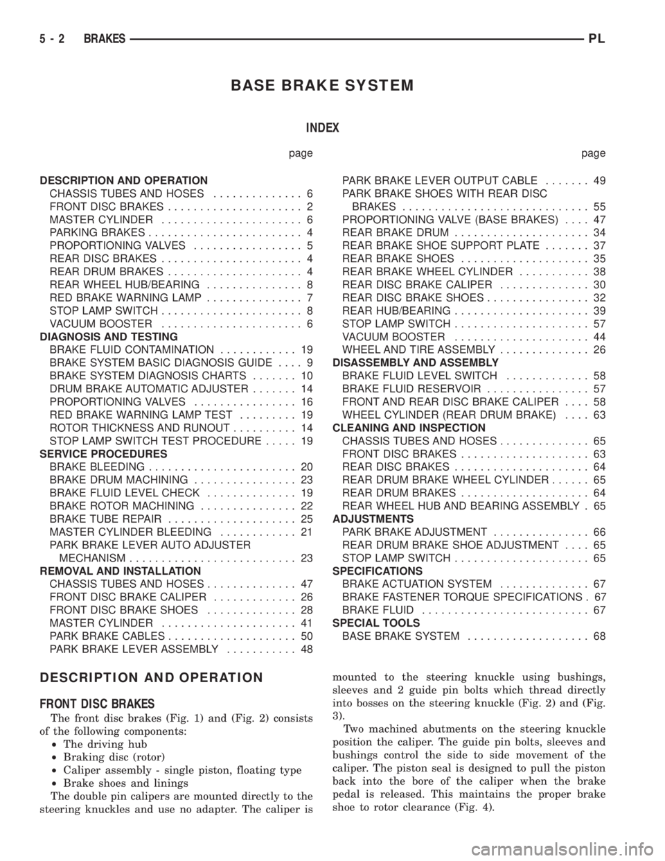
BASE BRAKE SYSTEM
INDEX
page page
DESCRIPTION AND OPERATION
CHASSIS TUBES AND HOSES.............. 6
FRONT DISC BRAKES..................... 2
MASTER CYLINDER...................... 6
PARKING BRAKES........................ 4
PROPORTIONING VALVES................. 5
REAR DISC BRAKES...................... 4
REAR DRUM BRAKES..................... 4
REAR WHEEL HUB/BEARING............... 8
RED BRAKE WARNING LAMP............... 7
STOP LAMP SWITCH...................... 8
VACUUM BOOSTER...................... 6
DIAGNOSIS AND TESTING
BRAKE FLUID CONTAMINATION............ 19
BRAKE SYSTEM BASIC DIAGNOSIS GUIDE.... 9
BRAKE SYSTEM DIAGNOSIS CHARTS....... 10
DRUM BRAKE AUTOMATIC ADJUSTER....... 14
PROPORTIONING VALVES................ 16
RED BRAKE WARNING LAMP TEST......... 19
ROTOR THICKNESS AND RUNOUT.......... 14
STOP LAMP SWITCH TEST PROCEDURE..... 19
SERVICE PROCEDURES
BRAKE BLEEDING....................... 20
BRAKE DRUM MACHINING................ 23
BRAKE FLUID LEVEL CHECK.............. 19
BRAKE ROTOR MACHINING............... 22
BRAKE TUBE REPAIR.................... 25
MASTER CYLINDER BLEEDING............ 21
PARK BRAKE LEVER AUTO ADJUSTER
MECHANISM.......................... 23
REMOVAL AND INSTALLATION
CHASSIS TUBES AND HOSES.............. 47
FRONT DISC BRAKE CALIPER............. 26
FRONT DISC BRAKE SHOES.............. 28
MASTER CYLINDER..................... 41
PARK BRAKE CABLES.................... 50
PARK BRAKE LEVER ASSEMBLY........... 48PARK BRAKE LEVER OUTPUT CABLE....... 49
PARK BRAKE SHOES WITH REAR DISC
BRAKES............................. 55
PROPORTIONING VALVE (BASE BRAKES).... 47
REAR BRAKE DRUM..................... 34
REAR BRAKE SHOE SUPPORT PLATE....... 37
REAR BRAKE SHOES.................... 35
REAR BRAKE WHEEL CYLINDER........... 38
REAR DISC BRAKE CALIPER.............. 30
REAR DISC BRAKE SHOES................ 32
REAR HUB/BEARING..................... 39
STOP LAMP SWITCH..................... 57
VACUUM BOOSTER..................... 44
WHEEL AND TIRE ASSEMBLY.............. 26
DISASSEMBLY AND ASSEMBLY
BRAKE FLUID LEVEL SWITCH............. 58
BRAKE FLUID RESERVOIR................ 57
FRONT AND REAR DISC BRAKE CALIPER.... 58
WHEEL CYLINDER (REAR DRUM BRAKE).... 63
CLEANING AND INSPECTION
CHASSIS TUBES AND HOSES.............. 65
FRONT DISC BRAKES.................... 63
REAR DISC BRAKES..................... 64
REAR DRUM BRAKE WHEEL CYLINDER...... 65
REAR DRUM BRAKES.................... 64
REAR WHEEL HUB AND BEARING ASSEMBLY . 65
ADJUSTMENTS
PARK BRAKE ADJUSTMENT............... 66
REAR DRUM BRAKE SHOE ADJUSTMENT.... 65
STOP LAMP SWITCH..................... 65
SPECIFICATIONS
BRAKE ACTUATION SYSTEM.............. 67
BRAKE FASTENER TORQUE SPECIFICATIONS . 67
BRAKE FLUID.......................... 67
SPECIAL TOOLS
BASE BRAKE SYSTEM................... 68
DESCRIPTION AND OPERATION
FRONT DISC BRAKES
The front disc brakes (Fig. 1) and (Fig. 2) consists
of the following components:
²The driving hub
²Braking disc (rotor)
²Caliper assembly - single piston, floating type
²Brake shoes and linings
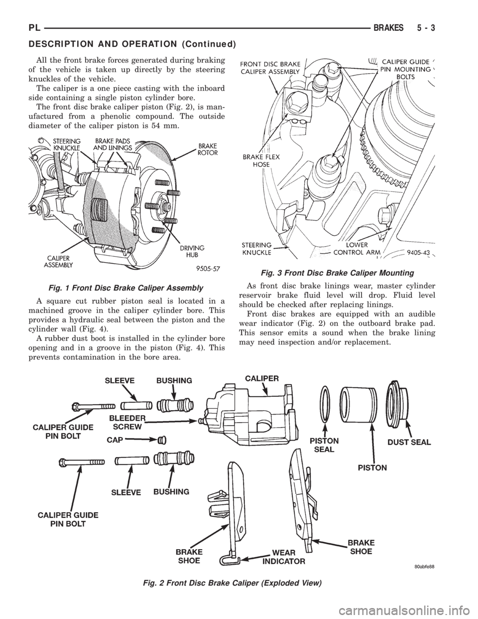
The double pin calipers are mounted directly to the
steering knuckles and use no adapter. The caliper ismounted to the steering knuckle using bushings,
sleeves and 2 guide pin bolts which thread directly
into bosses on the steering knuckle (Fig. 2) and (Fig.
3).
Two machined abutments on the steering knuckle
position the caliper. The guide pin bolts, sleeves and
bushings control the side to side movement of the
caliper. The piston seal is designed to pull the piston
back into the bore of the caliper when the brake
pedal is released. This maintains the proper brake
shoe to rotor clearance (Fig. 4).
5 - 2 BRAKESPL
Page 84 of 1200
All the front brake forces generated during braking
of the vehicle is taken up directly by the steering
knuckles of the vehicle.
The caliper is a one piece casting with the inboard
side containing a single piston cylinder bore.
The front disc brake caliper piston (Fig. 2), is man-
ufactured from a phenolic compound. The outside
diameter of the caliper piston is 54 mm.
A square cut rubber piston seal is located in a
machined groove in the caliper cylinder bore. This
provides a hydraulic seal between the piston and the
cylinder wall (Fig. 4).
A rubber dust boot is installed in the cylinder bore
opening and in a groove in the piston (Fig. 4). This
prevents contamination in the bore area.As front disc brake linings wear, master cylinder
reservoir brake fluid level will drop. Fluid level
should be checked after replacing linings.
Front disc brakes are equipped with an audible
wear indicator (Fig. 2) on the outboard brake pad.
This sensor emits a sound when the brake lining
may need inspection and/or replacement.
Fig. 1 Front Disc Brake Caliper Assembly
Fig. 2 Front Disc Brake Caliper (Exploded View)
Fig. 3 Front Disc Brake Caliper Mounting
PLBRAKES 5 - 3
DESCRIPTION AND OPERATION (Continued)