oil type DODGE NEON 1999 Service Owner's Manual
[x] Cancel search | Manufacturer: DODGE, Model Year: 1999, Model line: NEON, Model: DODGE NEON 1999Pages: 1200, PDF Size: 35.29 MB
Page 714 of 1200
ENGINE
CONTENTS
page page
2.0L DOHC ENGINE...................... 58
2.0L SOHC ENGINE...................... 12ENGINE DIAGNOSIS....................... 7
STANDARD SERVICE PROCEDURES.......... 1
STANDARD SERVICE PROCEDURES
INDEX
page page
GENERAL INFORMATION
CHECKING ENGINE OIL LEVEL.............. 5
CRANKSHAFT SPROCKET BOLT ACCESS
PLUG................................ 2
ENGINE CORE PLUGS.................... 2
ENGINE OIL SERVICE..................... 5
ENGINE PERFORMANCE.................. 2FORM-IN-PLACE GASKETS................. 1
HONING CYLINDER BORES................ 3
HYDROSTATIC LOCKED ENGINE............ 4
MEASURING MAIN BEARING AND
CONNECTING ROD BEARING CLEARANCES . 3
REPAIR OF DAMAGED OR WORN THREADS . . . 4
GENERAL INFORMATION
FORM-IN-PLACE GASKETS
There are numerous places where form-in-place
gaskets are used on the engine. Care must be taken
when applying form-in-place gaskets to assure
obtaining the desired results.Do not use form-in-
place gasket material unless specified.Bead size,
continuity, and location are of great importance. Too
thin a bead can result in leakage while too much can
result in spill-over which can break off and obstruct
fluid feed lines. A continuous bead of the proper
width is essential to obtain a leak-free gasket.
There are numerous types of form-in-place gasket
materials that are used in the engine area. Mopart
Silicone Rubber Adhesive Sealant and MopartGas-
ket Maker gasket materials, each have different
properties and can not be used in place of the other.
MOPARtSILICONE RUBBER ADHESIVE
SEALANT
MopartSilicone Rubber Adhesive Sealant or equiv-
alent, normally black in color, is available in three
ounce tubes. Moisture in the air causes the Mopart
Silicone Rubber Adhesive Sealant material to cure.
This material is normally used on flexible metal
flanges. It has a shelf life of one year and will not
properly cure if over age. Always inspect the package
for the expiration date before use.MOPARtGASKET MAKER
MopartGasket Maker is an anaerobic type gasket
material. The material cures in the absence of air
when squeezed between two metallic surfaces. It will
not cure if left in the uncovered tube. The anaerobic
material is for use between two machined surfaces.
Do not use on flexible metal flanges.
MOPARtTORQUE CURE GASKET MAKER
MopartTorque Cure Gasket Maker is a unique
anaerobic type gasket material to be usedONLY
between the bedplate and engine block. The material
cures in the absence of air when torqued between
two metallic surfaces. It will not cure if left in the
uncovered tube. This anaerobic material is specially
made to seal the area between the bedplate and cyl-
inder block without disturbing the bearing clearance
or alignment of these components.
GASKET DISASSEMBLY
Parts assembled with form-in-place gaskets may be
disassembled without unusual effort. In some
instances, it may be necessary to lightly tap the part
with a mallet or other suitable tool to break the seal
between the mating surfaces. A flat gasket scraper
may also be lightly tapped into the joint but care
must be taken not to damage the mating surfaces.
SURFACE PREPARATION
Scrape clean or wire brush all gasket surfaces
removing all loose material. Inspect stamped parts to
PLENGINE 9 - 1
Page 718 of 1200
(2) Remove negative battery cable.
(3) Place a shop towel around the spark plugs
when removing them from the engine. This will catch
any fluid that may possibly be in the cylinder under
pressure.
(4) With all spark plugs removed, rotate engine
crankshaft using a breaker bar and socket.
(5) Identify the fluid in the cylinder(s) (i.e., cool-
ant, fuel, oil or other).
(6) Make sure all fluid has been removed from the
cylinders. Inspect engine for damage (i.e., Connecting
Rods, Pistons, Valves etc.)
(7) Repair engine or components as necessary to
prevent this problem from occurring again.
CAUTION: Squirt approximately 1 teaspoon of oil
into cylinders, rotate engine to lubricate the cylin-
der walls to prevent damage on restart.
(8) Install new spark plugs.
(9) Drain engine oil and remove oil filter.
(10) Fill engine with specified amount of approved
oil and install new oil filter.
(11) Connect negative battery cable.
(12) Start engine and check for any leaks.
CHECKING ENGINE OIL LEVEL
The best time to check engine oil level is after it
has sat overnight, or if the engine has been running,
allow the engine to be shut off for at least 5 minutes
before checking oil level.
Checking the oil while the vehicle is on level
ground will improve the accuracy of the oil level
reading. Add only when the level is at or below the
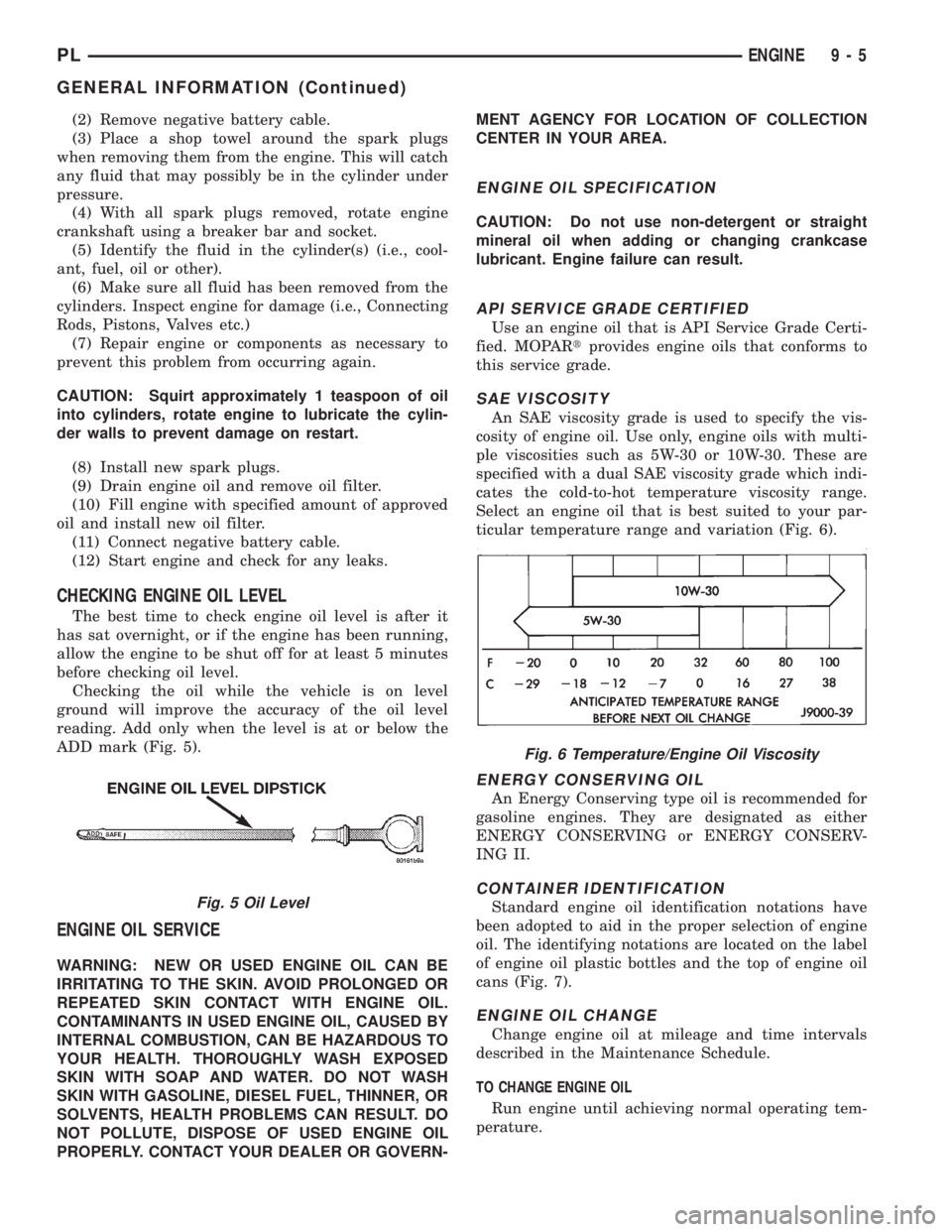
ADD mark (Fig. 5).
ENGINE OIL SERVICE
WARNING: NEW OR USED ENGINE OIL CAN BE
IRRITATING TO THE SKIN. AVOID PROLONGED OR
REPEATED SKIN CONTACT WITH ENGINE OIL.
CONTAMINANTS IN USED ENGINE OIL, CAUSED BY
INTERNAL COMBUSTION, CAN BE HAZARDOUS TO
YOUR HEALTH. THOROUGHLY WASH EXPOSED
SKIN WITH SOAP AND WATER. DO NOT WASH
SKIN WITH GASOLINE, DIESEL FUEL, THINNER, OR
SOLVENTS, HEALTH PROBLEMS CAN RESULT. DO
NOT POLLUTE, DISPOSE OF USED ENGINE OIL
PROPERLY. CONTACT YOUR DEALER OR GOVERN-MENT AGENCY FOR LOCATION OF COLLECTION
CENTER IN YOUR AREA.
ENGINE OIL SPECIFICATION
CAUTION: Do not use non-detergent or straight
mineral oil when adding or changing crankcase
lubricant. Engine failure can result.
API SERVICE GRADE CERTIFIED
Use an engine oil that is API Service Grade Certi-
fied. MOPARtprovides engine oils that conforms to
this service grade.
SAE VISCOSITY
An SAE viscosity grade is used to specify the vis-
cosity of engine oil. Use only, engine oils with multi-
ple viscosities such as 5W-30 or 10W-30. These are
specified with a dual SAE viscosity grade which indi-
cates the cold-to-hot temperature viscosity range.
Select an engine oil that is best suited to your par-
ticular temperature range and variation (Fig. 6).
ENERGY CONSERVING OIL
An Energy Conserving type oil is recommended for
gasoline engines. They are designated as either
ENERGY CONSERVING or ENERGY CONSERV-
ING II.
CONTAINER IDENTIFICATION
Standard engine oil identification notations have
been adopted to aid in the proper selection of engine
oil. The identifying notations are located on the label
of engine oil plastic bottles and the top of engine oil
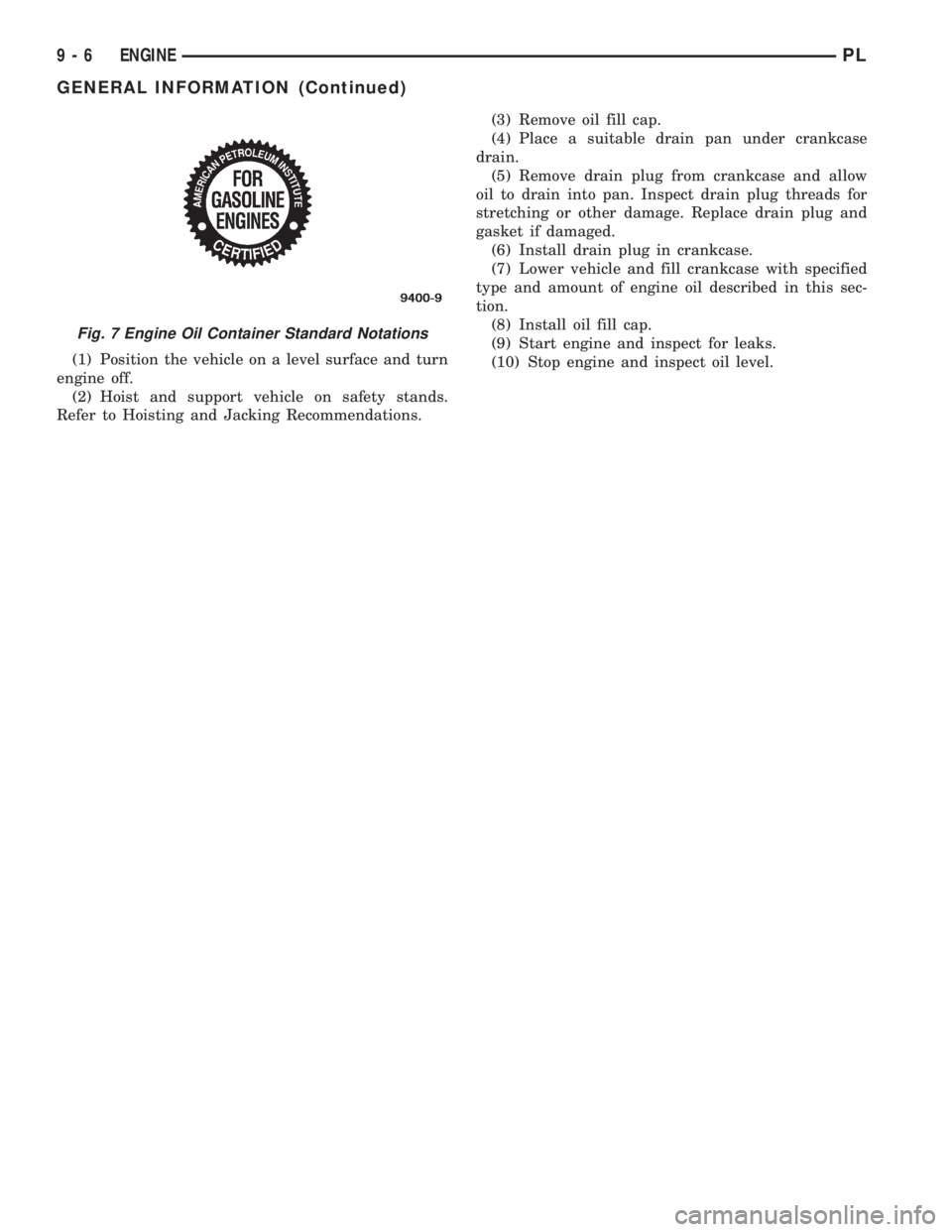
cans (Fig. 7).
ENGINE OIL CHANGE
Change engine oil at mileage and time intervals
described in the Maintenance Schedule.
TO CHANGE ENGINE OIL
Run engine until achieving normal operating tem-
perature.
Fig. 5 Oil Level
Fig. 6 Temperature/Engine Oil Viscosity
PLENGINE 9 - 5
GENERAL INFORMATION (Continued)
Page 719 of 1200
(1) Position the vehicle on a level surface and turn
engine off.
(2) Hoist and support vehicle on safety stands.
Refer to Hoisting and Jacking Recommendations.(3) Remove oil fill cap.
(4) Place a suitable drain pan under crankcase
drain.
(5) Remove drain plug from crankcase and allow
oil to drain into pan. Inspect drain plug threads for
stretching or other damage. Replace drain plug and
gasket if damaged.
(6) Install drain plug in crankcase.
(7) Lower vehicle and fill crankcase with specified
type and amount of engine oil described in this sec-
tion.
(8) Install oil fill cap.
(9) Start engine and inspect for leaks.
(10) Stop engine and inspect oil level.
Fig. 7 Engine Oil Container Standard Notations
9 - 6 ENGINEPL
GENERAL INFORMATION (Continued)
Page 725 of 1200
2.0L SOHC ENGINE
INDEX
page page
DESCRIPTION AND OPERATION
ENGINE COMPONENTS.................. 14
ENGINE IDENTIFICATION................. 12
ENGINE LUBRICATION SYSTEM............ 13
GENERAL SPECIFICATION................ 12
DIAGNOSIS AND TESTING
CHECKING ENGINE OIL PRESSURE......... 14
SERVICE PROCEDURES
CRANKSHAFT END PLAY................. 16
CYLINDER BORE AND PISTON SIZING....... 14
FITTING CONNECTING RODS.............. 16
FITTING CRANKSHAFT BEARINGS.......... 16
FITTING PISTON RINGS.................. 16
REMOVAL AND INSTALLATION
CAMSHAFT OIL SEAL.................... 28
CAMSHAFT............................ 22
CRANKSHAFT DAMPER.................. 46
CRANKSHAFT OIL SEALÐFRONT........... 37
CRANKSHAFT OIL SEALÐREAR............ 38
CRANKSHAFT.......................... 39
CYLINDER HEAD COVER................. 21
CYLINDER HEAD........................ 25
ENGINE ASSEMBLY...................... 19
ENGINE MOUNTÐFRONT................. 18
ENGINE MOUNTÐLEFT................... 18
ENGINE MOUNTÐRIGHT................. 18
OIL FILTER ADAPTER.................... 42OILFILTER ............................ 42
OILPAN ............................... 36
OIL PUMP............................. 42
PISTON AND CONNECTING ROD........... 44
POWER HOP DAMPER................... 18
ROCKER ARM/HYDRAULIC LASH ADJUSTER . . 23
SPARK PLUG TUBE...................... 21
STRUCTURAL COLLARÐ2.0L.............. 19
TIMING BELT COVER.................... 27
TIMING BELT TENSIONERÐMECHANICAL.... 36
TIMING BELTÐWITH HYDRAULIC TENSIONER . 28
TIMING BELTÐWITH MECHANICAL
TENSIONER.......................... 33
VALVE SEALS AND SPRINGS IN VEHICLE.... 24
DISASSEMBLY AND ASSEMBLY
OIL PUMP............................. 47
VALVE SERVICE WITH THE CYLINDER HEAD
REMOVED........................... 47
CLEANING AND INSPECTION
CYLINDER BLOCK AND BORE............. 51
CYLINDER HEAD AND CAMSHAFT JOURNALS . 50
OIL PUMP............................. 50
SPECIFICATIONS
2.0L SOHC............................. 52
TORQUE CHART 2.0L SOHC............... 54
SPECIAL TOOLS
2.0L SOHC............................. 55
DESCRIPTION AND OPERATION
ENGINE IDENTIFICATION
The engine identification number is located on the
left rear of the cylinder block behind starter (Fig. 1).
GENERAL SPECIFICATION
Type ..............In-Line OHV, DOHC & SOHC
Bore......................87.5mm (3.445 Inch)
Stroke.....................83.0mm (3.268 inch)
Compression Ratio.....DOHC - 9.6:1 SOHC - 9.8:1
Displacement..........2.0 Liters (122 Cubic Inch)
Firing Order.........................1,3,4,2
Compression Pressure............1172-1551 kPa
(170 - 225 psi)
Maximum Variation Between Cylinders.......25%
Lubrication. . . .Pressure Feed - Full Flow Filtration
(Crankshaft Driven Pump)
Engine Oil Capacity............Refer to Group 0,
Lubrication and Maintenance
Fig. 1 Engine Identification SOHC
9 - 12 2.0L SOHC ENGINEPL
Page 726 of 1200
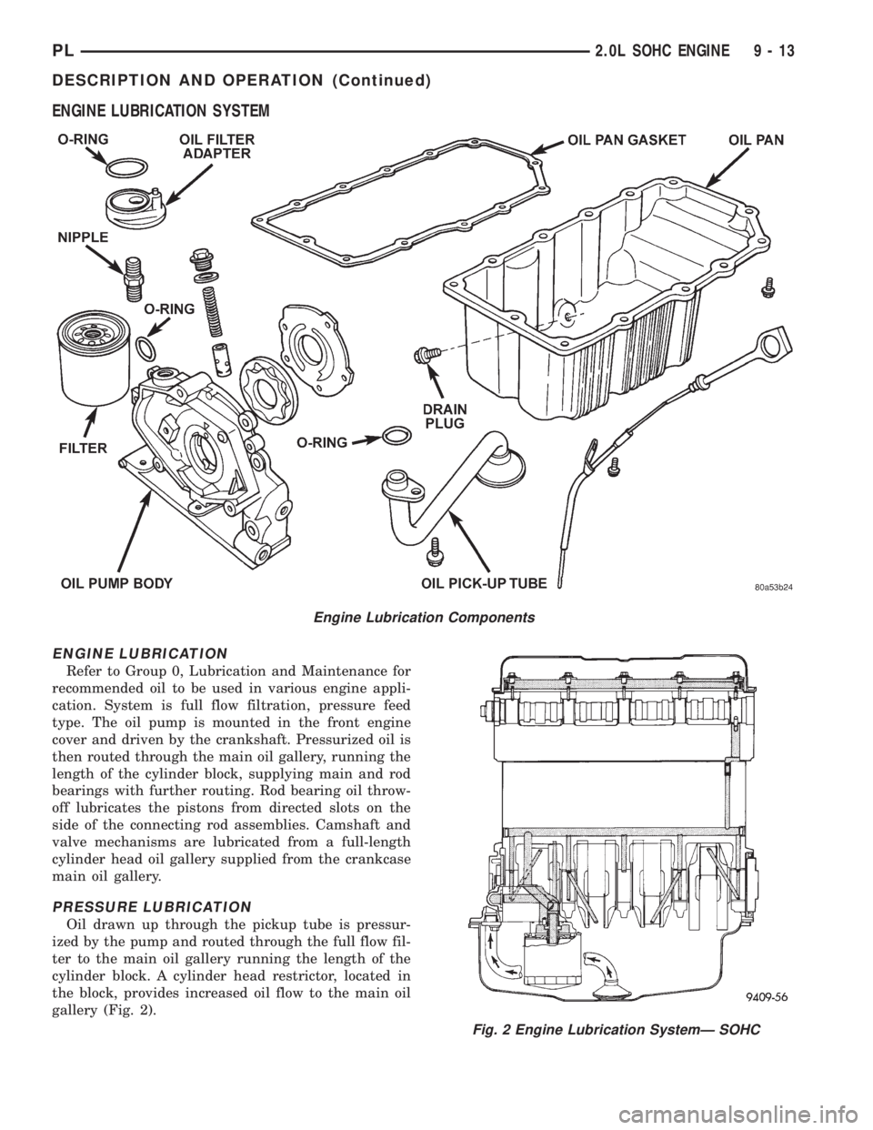
ENGINE LUBRICATION SYSTEM
ENGINE LUBRICATION
Refer to Group 0, Lubrication and Maintenance for
recommended oil to be used in various engine appli-
cation. System is full flow filtration, pressure feed
type. The oil pump is mounted in the front engine
cover and driven by the crankshaft. Pressurized oil is
then routed through the main oil gallery, running the
length of the cylinder block, supplying main and rod
bearings with further routing. Rod bearing oil throw-
off lubricates the pistons from directed slots on the
side of the connecting rod assemblies. Camshaft and
valve mechanisms are lubricated from a full-length
cylinder head oil gallery supplied from the crankcase
main oil gallery.
PRESSURE LUBRICATION
Oil drawn up through the pickup tube is pressur-
ized by the pump and routed through the full flow fil-
ter to the main oil gallery running the length of the
cylinder block. A cylinder head restrictor, located in
the block, provides increased oil flow to the main oil
gallery (Fig. 2).
Engine Lubrication Components
Fig. 2 Engine Lubrication SystemÐ SOHC
PL2.0L SOHC ENGINE 9 - 13
DESCRIPTION AND OPERATION (Continued)
Page 771 of 1200
2.0L DOHC ENGINE
INDEX
page page
DESCRIPTION AND OPERATION
ENGINE COMPONENTS.................. 59
ENGINE IDENTIFICATION NUMBER......... 58
ENGINE LUBRICATION SYSTEM............ 58
GENERAL SPECIFICATION................ 58
DIAGNOSIS AND TESTING
CHECKING ENGINE OIL PRESSURE......... 60
SERVICE PROCEDURES
CRANKSHAFT END PLAY................. 63
CYLINDER BORE AND PISTON SIZING....... 60
FITTING CONNECTING RODS.............. 62
FITTING CRANKSHAFT BEARINGS.......... 62
FITTING PISTON RINGS.................. 61
REMOVAL AND INSTALLATION
CAMSHAFT OIL SEALS................... 81
CAM FOLLOWER AND HYDRAULIC LASH
ADJUSTER ASSEMBLY.................. 69
CAMSHAFT............................ 67
CRANKSHAFT DAMPER.................. 73
CRANKSHAFT OIL SEALÐFRONT........... 82
CRANKSHAFT OIL SEALÐREAR............ 83
CRANKSHAFT.......................... 85
CYLINDER HEAD COVER................. 67
CYLINDER HEAD........................ 71
ENGINE ASSEMBLY...................... 65
ENGINE MOUNTÐFRONT................. 63
ENGINE MOUNTÐLEFT................... 63
ENGINE MOUNTÐRIGHT................. 64OIL FILTER ADAPTER.................... 87
OILFILTER ............................ 87
OILPAN ............................... 81
OIL PUMP............................. 88
PISTON AND CONNECTING ROD........... 89
POWER HOP DAMPER................... 64
STRUCTURAL COLLARÐ2.0L.............. 64
TIMING BELT COVER.................... 74
TIMING BELT TENSIONERÐMECHANICAL.... 80
TIMING BELTÐWITH HYDRAULIC TENSIONER . 75
TIMING BELTÐWITH MECHANICAL
TENSIONER.......................... 78
VALVE SPRING AND SEALSÐ
CYLINDER HEAD NOT REMOVED......... 69
DISASSEMBLY AND ASSEMBLY
OIL PUMP............................. 91
VALVE SERVICE WITH CYLINDER HEAD
REMOVED........................... 91
CLEANING AND INSPECTION
CYLINDER BLOCK AND BORE............. 96
CYLINDER HEAD AND CAMSHAFT JOURNALS . 94
OIL PUMP............................. 94
SPECIFICATIONS
2.0L DOHC............................. 96
TORQUE CHART 2.0L DOHC............... 98
SPECIAL TOOLS
2.0L DOHC............................. 98
DESCRIPTION AND OPERATION
ENGINE IDENTIFICATION NUMBER
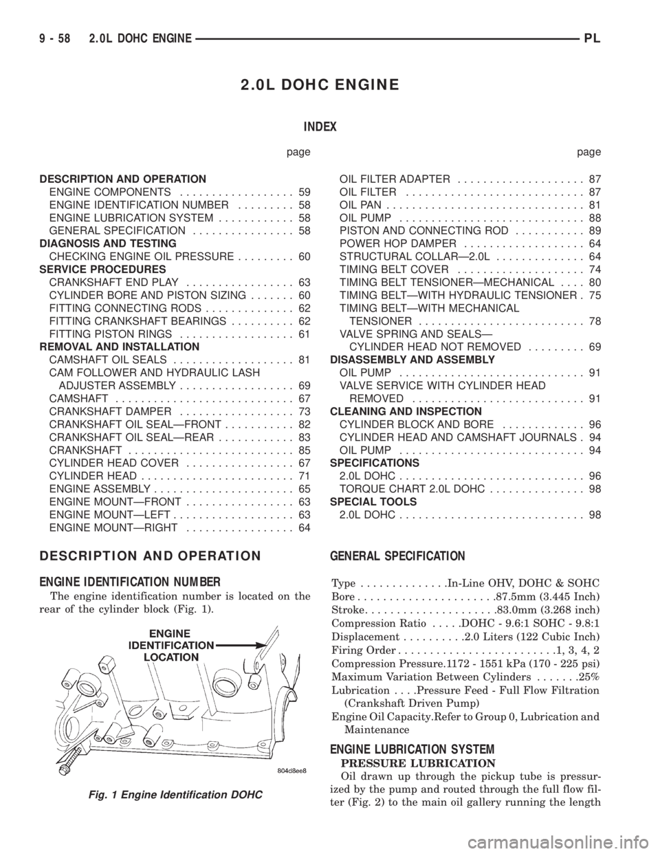
The engine identification number is located on the
rear of the cylinder block (Fig. 1).
GENERAL SPECIFICATION
Type ..............In-Line OHV, DOHC & SOHC
Bore......................87.5mm (3.445 Inch)
Stroke.....................83.0mm (3.268 inch)
Compression Ratio.....DOHC - 9.6:1 SOHC - 9.8:1
Displacement..........2.0 Liters (122 Cubic Inch)
Firing Order.........................1,3,4,2
Compression Pressure.1172 - 1551 kPa (170 - 225 psi)
Maximum Variation Between Cylinders.......25%
Lubrication. . . .Pressure Feed - Full Flow Filtration
(Crankshaft Driven Pump)
Engine Oil Capacity.Refer to Group 0, Lubrication and
Maintenance
ENGINE LUBRICATION SYSTEM
PRESSURE LUBRICATION
Oil drawn up through the pickup tube is pressur-
ized by the pump and routed through the full flow fil-
ter (Fig. 2) to the main oil gallery running the length
Fig. 1 Engine Identification DOHC
9 - 58 2.0L DOHC ENGINEPL
Page 773 of 1200
incorporates main bearing caps. Rear seal retainer is
integral with the block.
CRANKSHAFTA nodular cast iron crankshaft is
used. The engine has 5 main bearings, with number
3 flanged to control thrust. The 52 mm diameter
main and 48 mm diameter crank pin journals (all)
have undercut fillet radiuses that are deep rolled for
added strength. To optimize bearing loading 8 coun-
terweights are used. Hydrodynamic seals provide end
sealing, where the crankshaft exits the block.
Anaerobic gasket material is used for parting line
sealing. A sintered iron timing belt sprocket is
mounted on the crankshaft nose. This sprocket pro-
vides motive power; via timing belt to the camshaft
sprocket providing timed valve actuation.
PISTONSThe DOHC EngineDO NOThave pro-
vision for a free wheeling valve train. Non free
wheeling valve train means, in the event of a broken
timing belt Pistons will contact the Valves. All
engines use pressed-in piston pins to attach forged
powdered metal connecting rods. The connecting rods
are a cracked cap design and are not repairable. Hex
head cap screw are used to provide alignment and
durability in the assembly.
PISTON RINGSThe piston rings include a
molybdenum faced top ring for reliable compression
sealing and a taper faced intermediate ring for addi-
tional cylinder pressure control. Oil Control Ring
Package contains of 2 steel rails and a expander
spacer.
CYLINDER HEADFeatures a Dual Over Head
Camshaft (DOHC), 4 valves per cylinder cross flow
design. The valves are arranged in two in-line banks,
with the ports of the bank of two intake valves per
cylinder facing toward the radiator side of engine
and ports of the bank of two exhaust valves per cyl-
inder facing toward the dash panel. Incorporates
powder metal valve guides and seats. Integral oil gal-
leys within the cylinder head supplies oil to the
hydraulic lash adjusters, camshaft and valve mecha-
nisms.
CAMSHAFTSThe nodular iron camshafts have
six bearing journals and 2 cam lobes per cylinder.
Flanges at the rear journals control camshaft end
play. Provision for cam position sensor is located on
the intake camshaft at the rear of cylinder head. A
hydrodynamic oil seal is used for oil control at the
front of the camshaft.
VA LV E SFour valves per cylinder are actuated by
roller cam followers which pivot on stationary
hydraulic lash adjusters. All valves have 6 mm diam-
eter chrome plated valve stems. The valve sizes are
34.8 mm (1.370 inch.) diameter intake valves and
30.5 mm (1.20 inch.) diameter exhaust valves. Viton
rubber valve stem seals are integral with the springseats. Valve springs, spring retainers, and locks are
conventional.
INTAKE MANIFOLDThe intake manifold is a
two piece aluminum casting, attached to the cylinder
head with ten fasteners. This long branch fan design
enhances low and mid-speed torque.
EXHAUST MANIFOLDThe exhaust manifold is
made of nodular cast iron for strength and high tem-
peratures. Exhaust gasses exit through a machined,
articulated joint connection to the exhaust pipe.
COMPONENT REPLACEMENT
If any of the following parts have been changed or
replaced:
²Camshaft
²Camshaft Position Sensor
²Camshaft Position Sensor Target Magnet
²Cylinder Block
²Cylinder Head
²Water Pump
²Powertrain Control Module (PCM)
²Timing Belt and Timing Belt Tensioner
The camshaft and crankshaft timing relearn proce-
dure must be performed. Refer to the component
Removal and Installation procedure outlined in this
Group.
DIAGNOSIS AND TESTING
CHECKING ENGINE OIL PRESSURE
(1) Remove oil pressure switch and install gauge
assembly C-3292 with adaptor.
(2) Run engine until thermostat opens.
CAUTION: If oil pressure is 0 at idle, Do Not per-
form the 3000 RPM test in the next step.
(3) Oil Pressure:Curb Idle25 kPa (4 psi) mini-
mum3000 RPM170-550 kPa (25-80 psi).
(4) If oil pressure is 0 at idle. Shut off engine,
check for pressure relief valve stuck open, a clogged
oil pick-up screen or a damaged oil pick-up tube
O-ring.
SERVICE PROCEDURES
CYLINDER BORE AND PISTON SIZING
The cylinder walls should be checked for out-of-
round and taper with Tool C-119 (Fig. 4). The cylin-
der bore out-of-round is 0.050 mm (.002 inch)
maximum and cylinder bore taper is 0.051 mm (0.002
inch) maximum. If the cylinder walls are badly
scuffed or scored, the cylinder block should be
rebored and honed, and new pistons and rings fitted.
Whatever type of boring equipment is used, boring
and honing operation should be closely coordinated
9 - 60 2.0L DOHC ENGINEPL
DESCRIPTION AND OPERATION (Continued)
Page 814 of 1200
ENGINE
CONTENTS
page
1.8L SOHC ENGINE...................... 1
1.8L SOHC ENGINE
INDEX
page
GENERAL INFORMATION
1.8L SOHC ENGINE...................... 1
GENERAL INFORMATION
1.8L SOHC ENGINE
For service of the 1.8L SOHC engine refer to the
2.0L SOHC engine information except for the follow-
ing specifications.
GENERAL SPECIFICATIONS
Type .....................In-Line OHV, SOHC
Bore..............................83.0 mm
Stroke.............................83.0mm
Compression Ratio.....................10.0:1
Displacement......................1.8Liters
Firing Order........................1,3,4,2
Compression (Cranking)
Pressure.......1172-1551 kPa (170 - 225 psi)
Maximum Variation Between Cylinders......25%
Lubrication . . . Pressure Feed - Full Flow Filtration
(Crankshaft Driven Pump)
CYLINDER BORE AND PISTON
SPECIFICATIONS CHART
Standard Bore Maximum
Out-of-RoundMaximum
Taper
82.993 - 83.007
mm0.051 mm 0.051 mm
Standard Piston Size
82.974 - 82.956 mm
Piston to Bore Clearance
0.018 - 0.050 mm
Measurements Taken at Piston Size Location
PISTON RING SPECIFICATIONS
Ring Position Ring Gap Wear Limit
Upper Ring 0.23 - 0.38 mm 0.8 mm
Intermediate
Ring0.20 - 0.47 mm 1.0 mm
Oil Control Ring 0.25 -0.64 mm 1.0 mm
Ring Position Groove
ClearanceMaximum
Clearance
Upper Ring 0.03 - 0.07 mm 0.10 mm
Intermediate
Ring0.040 - 0.078
mm0.10 mm
OIL CONTROL RING (THREE PIECE) - OIL RING
SIDE RAILS MUST BE FREE TO ROTATE AFTER
ASSEMBLY
PLENGINE 9 - 1
Page 852 of 1200
The hose clamps have rolled edges to prevent the
clamp from cutting into the hose. Only use clamps
that are original equipment or equivalent. Other
types of clamps may cut into the hoses and cause
high pressure fuel leaks. Tighten hose clamps to 1
N´m (10 in. lbs.) torque.
QUICK-CONNECT FITTINGS
REMOVAL
When disconnecting a quick-connect fitting, the
retainer will remain on the fuel tube nipple.
WARNING: RELEASE FUEL SYSTEM PRESSURE
BEFORE DISCONNECTING A QUICK-CONNECT FIT-
TINGS. REFER TO THE FUEL PRESSURE RELEASE
PROCEDURE.
(1) Disconnect negative cable from battery.
(2) Perform Fuel Pressure Release Procedure.
Refer to the Fuel Pressure Release Procedure in this
section.
(3) Squeeze retainer tabs together and pull fuel
tube/quick-connect fitting assembly off of fuel tube
nipple. The retainer will remain on fuel tube.
INSTALLATION
CAUTION: Never install a quick-connect fitting
without the retainer being either on the fuel tube or
already in the quick-connect fitting. In either case,
ensure the retainer locks securely into the quick-
connect fitting by firmly pulling on fuel tube and fit-
ting to ensure it is secured.
(1) Using a clean lint free cloth, clean the fuel tube
nipple and retainer.
(2) Prior to connecting the fitting to the fuel tube,
coat the fuel tube nipple with clean 30 weight engine
oil.
(3) Push the quick-connect fitting over the fuel
tube until theretainer seats and a click is heard.
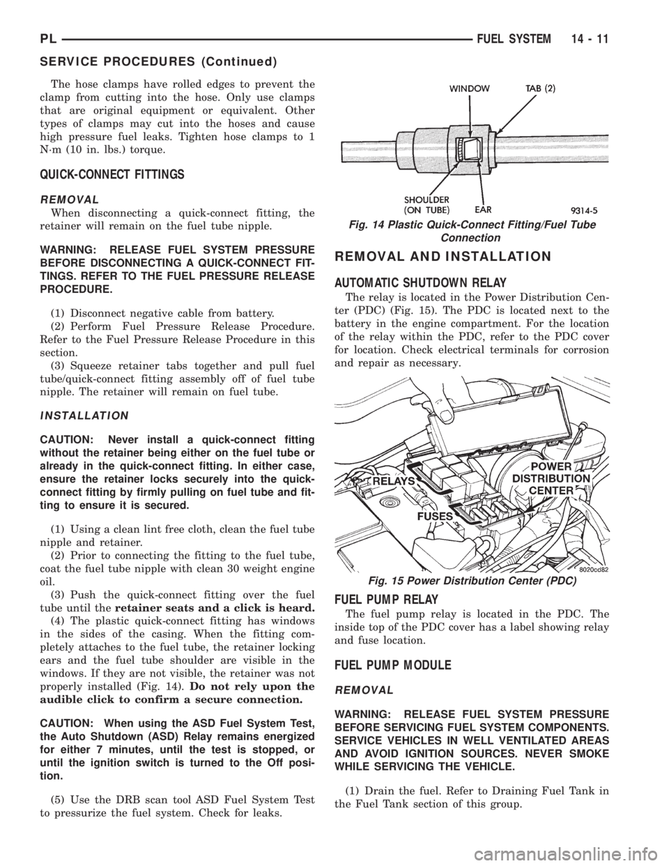
(4) The plastic quick-connect fitting has windows
in the sides of the casing. When the fitting com-
pletely attaches to the fuel tube, the retainer locking
ears and the fuel tube shoulder are visible in the
windows. If they are not visible, the retainer was not
properly installed (Fig. 14).Do not rely upon the
audible click to confirm a secure connection.
CAUTION: When using the ASD Fuel System Test,
the Auto Shutdown (ASD) Relay remains energized
for either 7 minutes, until the test is stopped, or
until the ignition switch is turned to the Off posi-
tion.
(5) Use the DRB scan tool ASD Fuel System Test
to pressurize the fuel system. Check for leaks.
REMOVAL AND INSTALLATION
AUTOMATIC SHUTDOWN RELAY
The relay is located in the Power Distribution Cen-
ter (PDC) (Fig. 15). The PDC is located next to the
battery in the engine compartment. For the location
of the relay within the PDC, refer to the PDC cover
for location. Check electrical terminals for corrosion
and repair as necessary.
FUEL PUMP RELAY
The fuel pump relay is located in the PDC. The
inside top of the PDC cover has a label showing relay
and fuse location.
FUEL PUMP MODULE
REMOVAL
WARNING: RELEASE FUEL SYSTEM PRESSURE
BEFORE SERVICING FUEL SYSTEM COMPONENTS.
SERVICE VEHICLES IN WELL VENTILATED AREAS
AND AVOID IGNITION SOURCES. NEVER SMOKE
WHILE SERVICING THE VEHICLE.
(1) Drain the fuel. Refer to Draining Fuel Tank in
the Fuel Tank section of this group.
Fig. 14 Plastic Quick-Connect Fitting/Fuel Tube
Connection
Fig. 15 Power Distribution Center (PDC)
PLFUEL SYSTEM 14 - 11
SERVICE PROCEDURES (Continued)
Page 902 of 1200
STEERING
CONTENTS
page page
GENERAL INFORMATION................... 1
POWER STEERING PUMP.................. 9STEERING COLUMN...................... 35
STEERING GEAR........................ 26
GENERAL INFORMATION
INDEX
page page
GENERAL INFORMATION
STEERING SYSTEM AND COMPONENT
DESCRIPTION......................... 1DIAGNOSIS AND TESTING
STEERING SYSTEM DIAGNOSIS CHARTS..... 2
GENERAL INFORMATION
STEERING SYSTEM AND COMPONENT
DESCRIPTION
This vehicle comes with power steering as stan-
dard equipment and is the only steering system
available.
The power steering system consists of these six
major components. Power Steering Pump, Power
Steering Gear, Power Steering Reservoir, Power
Steering Supply and Pressure Hoses, and Power
Steering Fluid Return Hose. Turning of the steering
wheel is converted into linear travel through themeshing of the helical pinion teeth with the rack
teeth. Power assist steering is provided by an open
center, rotary type control valve. It is used to direct
oil from the power steering pump to either side of the
integral steering rack piston.
Road feel is controlled by the diameter of a torsion
bar which initially steers the vehicle. As steering
effort increases as in a turn, the torsion bar twists,
causing relative rotary motion between the rotary
valve body and valve spool. This movement directs
oil behind the integral rack piston, which in turn,
builds up hydraulic pressure and assists in the turn-
ing effort.
PLSTEERING 19 - 1