instrument panel DODGE NEON 1999 Service Owner's Guide
[x] Cancel search | Manufacturer: DODGE, Model Year: 1999, Model line: NEON, Model: DODGE NEON 1999Pages: 1200, PDF Size: 35.29 MB
Page 341 of 1200
LAMP SYSTEMS
INDEX
page page
REMOVAL AND INSTALLATION
DAYTIME RUNNING LAMP (CANADA)........ 12
REMOVAL AND INSTALLATION
DAYTIME RUNNING LAMP (CANADA)
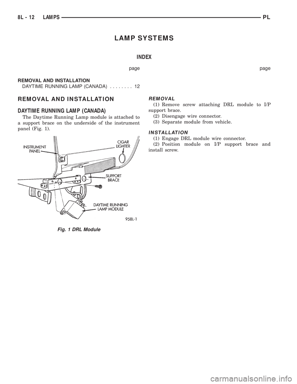
The Daytime Running Lamp module is attached to
a support brace on the underside of the instrument
panel (Fig. 1).
REMOVAL
(1) Remove screw attaching DRL module to I/P
support brace.
(2) Disengage wire connector.
(3) Separate module from vehicle.
INSTALLATION
(1) Engage DRL module wire connector.
(2) Position module on I/P support brace and
install screw.
Fig. 1 DRL Module
8L - 12 LAMPSPL
Page 342 of 1200
BULB APPLICATION
INDEX
page page
SPECIFICATIONS
EXTERIOR LAMPS....................... 13GENERAL INFORMATION................. 13
INTERIOR LAMPS....................... 13
SPECIFICATIONS
GENERAL INFORMATION
The following Bulb Application Tables lists the
lamp title on the left side of the column and trade
number or part number on the right.
CAUTION: Do not use bulbs that have a higher
candle power than the bulb listed in the Bulb Appli-
cation Table. Damage to lamp can result. Do not
touch halogen bulbs with fingers or other oily sur-
faces. Bulb life will be reduced.
EXTERIOR LAMPS
LAMP BULB
Back-up...............................3157
Center High Mounted Stop..................921
Fog.................................GE881
Headlamp..............................9007
License Plate............................168
Park/Turn Signal......................3157NA
Tail/Stop/Turn Signal.....................3157
Front Side Marker........................168
INTERIOR LAMPS
Service procedures for most of the lamps in the
instrument panel, Instrument cluster and switches
are located in Group 8E, Instrument Panel and
Gauges.
LAMP BULB
A/C and Heater Control....................203
Ash Receiver.............................161
Cigar Lighter............................203
Dome Lamp.............................578
Gear Selector Console W/Auto...............161
Glove Compartment.......................194
Ignition Lock............................161
Instrument Panel and Cluster.............PC194
Rear Cargo..............................912
Underhood..............................105
PLLAMPS 8L - 13
Page 344 of 1200
LAMPS
CONTENTS
page page
BULB APPLICATION....................... 8
LAMP BULB SERVICE..................... 2LAMP DIAGNOSIS........................ 1
LAMP SERVICE........................... 5
LAMP DIAGNOSIS
INDEX
page
GENERAL INFORMATION
HEADLAMP LEVELING MOTOR.............. 1
GENERAL INFORMATION
HEADLAMP LEVELING MOTOR
This vehicle is equipped with a remote headlamp
leveling system. This system allows the driver to
adjust the vertical headlamp aim from the interior ofthe vehicle to compensate for passenger or cargo
load. A headlamp leveling switch is located in the
instrument panel and controls the headlamp leveling
motor and leveling cable found mounted to the upper
radiator crossmember behind the headlamp assem-
bly.
PLLAMPS 8L - 1
Page 348 of 1200
LAMP SERVICE
INDEX
page page
GENERAL INFORMATION
HEADLAMP DIMMER SWITCH............... 5
HEADLAMP SWITCH...................... 5
REMOVAL AND INSTALLATION
FOG LAMP.............................. 6HEADLAMP ASSEMBLY.................... 5
HEADLAMP LEVELING MOTOR.............. 6
SIDE REPEATER LAMP.................... 6
GENERAL INFORMATION
HEADLAMP SWITCH
Service procedures for the headlamp switch can be
found in Group 8E, Instrument Panel and Gauges.
More information can be found in Group 8W, Wiring
Diagrams.
HEADLAMP DIMMER SWITCH
The headlamp dimmer switch is incorporated into
the multi-function (turn signal) switch. Proper proce-
dures can be found in Group 8J, Turn Signal and
Flashers. More information can be found in Group
8W, Wiring Diagrams.
REMOVAL AND INSTALLATION
HEADLAMP ASSEMBLY
REMOVAL
(1) Release hood latch and open hood.
(2) Remove headlamp horizontal aim cable from
retainer clip on radiator upper crossmember.
(3) Disengage wire connector from leveling motor.
(4) Remove bolts holding headlamp leveling motor
to the upper radiator crossmember.
(5) Remove plastic locking cap holding vertical lev-
eling cable into leveling motor arm.
(6) Separate leveling cable from motor arm.
(7) Rotate leveling cable case one quarter turn
counter-clockwise and separate cable from motor
bracket.
(8) Separate leveling motor and bracket from vehi-
cle.
(9) From between front fascia and headlamp
assembly, remove bolt holding outboard end of
assembly to fender.
(10) Remove bolts holding inboard end of assembly
to radiator closure panel.
(11) Remove bolts holding top of assembly to upper
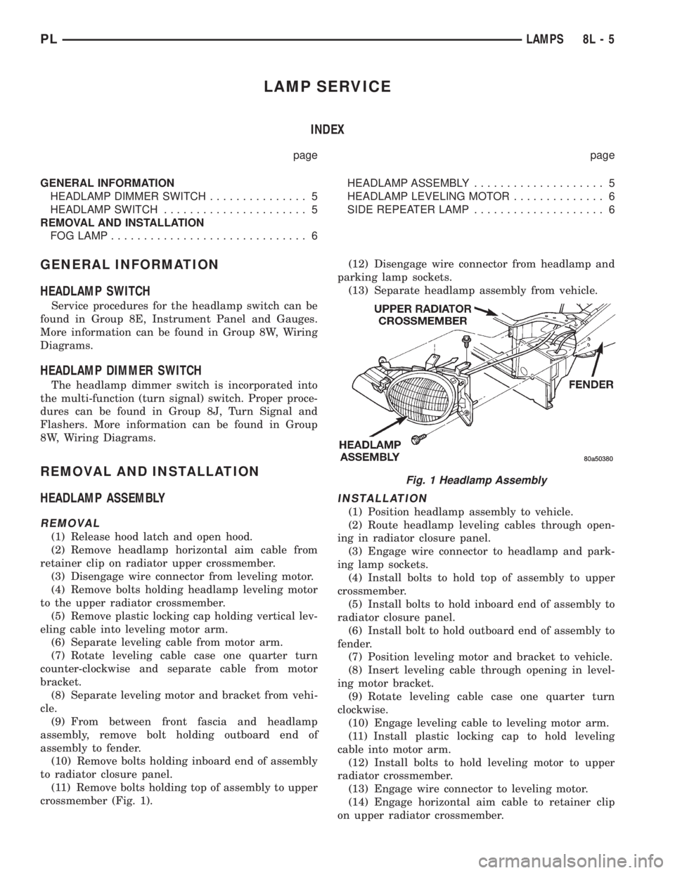
crossmember (Fig. 1).(12) Disengage wire connector from headlamp and
parking lamp sockets.
(13) Separate headlamp assembly from vehicle.
INSTALLATION
(1) Position headlamp assembly to vehicle.
(2) Route headlamp leveling cables through open-
ing in radiator closure panel.
(3) Engage wire connector to headlamp and park-
ing lamp sockets.
(4) Install bolts to hold top of assembly to upper
crossmember.
(5) Install bolts to hold inboard end of assembly to
radiator closure panel.
(6) Install bolt to hold outboard end of assembly to
fender.
(7) Position leveling motor and bracket to vehicle.
(8) Insert leveling cable through opening in level-
ing motor bracket.
(9) Rotate leveling cable case one quarter turn
clockwise.
(10) Engage leveling cable to leveling motor arm.
(11) Install plastic locking cap to hold leveling
cable into motor arm.
(12) Install bolts to hold leveling motor to upper
radiator crossmember.
(13) Engage wire connector to leveling motor.
(14) Engage horizontal aim cable to retainer clip
on upper radiator crossmember.
Fig. 1 Headlamp Assembly
PLLAMPS 8L - 5
Page 353 of 1200
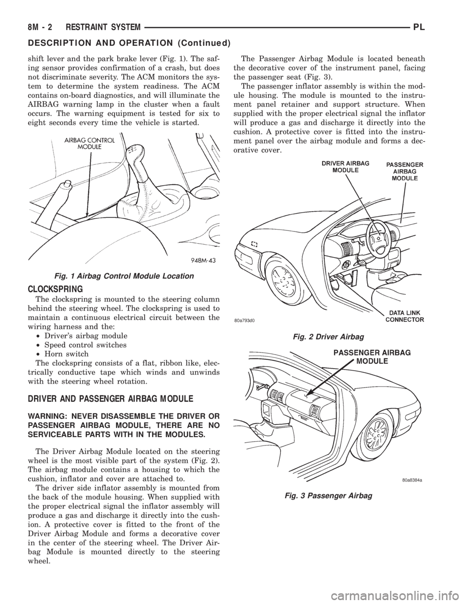
shift lever and the park brake lever (Fig. 1). The saf-
ing sensor provides confirmation of a crash, but does
not discriminate severity. The ACM monitors the sys-
tem to determine the system readiness. The ACM
contains on-board diagnostics, and will illuminate the
AIRBAG warning lamp in the cluster when a fault
occurs. The warning equipment is tested for six to
eight seconds every time the vehicle is started.
CLOCKSPRING
The clockspring is mounted to the steering column
behind the steering wheel. The clockspring is used to
maintain a continuous electrical circuit between the
wiring harness and the:
²Driver's airbag module
²Speed control switches
²Horn switch
The clockspring consists of a flat, ribbon like, elec-
trically conductive tape which winds and unwinds
with the steering wheel rotation.
DRIVER AND PASSENGER AIRBAG MODULE
WARNING: NEVER DISASSEMBLE THE DRIVER OR
PASSENGER AIRBAG MODULE, THERE ARE NO
SERVICEABLE PARTS WITH IN THE MODULES.
The Driver Airbag Module located on the steering
wheel is the most visible part of the system (Fig. 2).
The airbag module contains a housing to which the
cushion, inflator and cover are attached to.
The driver side inflator assembly is mounted from
the back of the module housing. When supplied with
the proper electrical signal the inflator assembly will
produce a gas and discharge it directly into the cush-
ion. A protective cover is fitted to the front of the
Driver Airbag Module and forms a decorative cover
in the center of the steering wheel. The Driver Air-
bag Module is mounted directly to the steering
wheel.The Passenger Airbag Module is located beneath
the decorative cover of the instrument panel, facing
the passenger seat (Fig. 3).
The passenger inflator assembly is within the mod-
ule housing. The module is mounted to the instru-
ment panel retainer and support structure. When
supplied with the proper electrical signal the inflator
will produce a gas and discharge it directly into the
cushion. A protective cover is fitted into the instru-
ment panel over the airbag module and forms a dec-
orative cover.
Fig. 1 Airbag Control Module Location
Fig. 2 Driver Airbag
Fig. 3 Passenger Airbag
8M - 2 RESTRAINT SYSTEMPL
DESCRIPTION AND OPERATION (Continued)
Page 354 of 1200
DIAGNOSIS AND TESTING
AIRBAG SYSTEM TEST
(1) Disconnect and isolate the negative battery
cable.
(2) Connect scan tool (DRB) to Data Link connec-
tor, located at right side of the steering column and
at the lower edge of the lower instrument panel.
(3) Turn the ignition key to ON position. Exit vehi-
cle with scan tool. Use the latest version of the
proper cartridge.
(4) After checking that no one is inside the vehicle,
connect the battery negative terminal.
(5) Using the scan tool, read and record active
diagnostic code data.
(6) Read and record any stored diagnostic codes.
(7) Refer to the Passive Restraint Diagnostic Test
Manual if any diagnostic codes are found in Step 5 or
Step 6.
(8) Erase stored diagnostic codes if there are no
active diagnostic codes. If problems remain, diagnos-
tic codes will not erase. Refer to the Passive
Restraint Diagnostic Test Manual to diagnose the
problem.If the airbag warning lamp either fails
to light with the ignition switch on, or the light
goes on and stays on, there is a system malfunc-
tion. Refer to the Passive Restraint Diagnostic
Test Manual to diagnose the problem.
SERVICE PROCEDURES
CLEANUP PROCEDURE
Roll or fold the passenger airbag towards the
instrument panel surface and close the door over the
folded bag. Then tape the door shut.
Use a vacuum cleaner to remove any residual pow-
der from the vehicle interior. Work from the outside
in to avoid kneeling or sitting in a contaminated
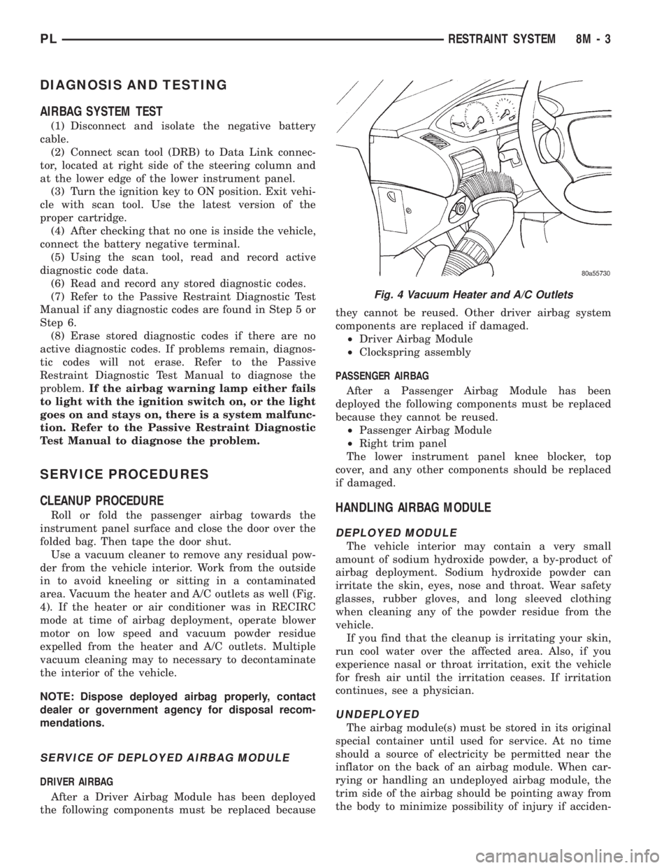
area. Vacuum the heater and A/C outlets as well (Fig.
4). If the heater or air conditioner was in RECIRC
mode at time of airbag deployment, operate blower
motor on low speed and vacuum powder residue
expelled from the heater and A/C outlets. Multiple
vacuum cleaning may to necessary to decontaminate
the interior of the vehicle.
NOTE: Dispose deployed airbag properly, contact
dealer or government agency for disposal recom-
mendations.
SERVICE OF DEPLOYED AIRBAG MODULE
DRIVER AIRBAG
After a Driver Airbag Module has been deployed
the following components must be replaced becausethey cannot be reused. Other driver airbag system
components are replaced if damaged.
²Driver Airbag Module
²Clockspring assembly
PASSENGER AIRBAG
After a Passenger Airbag Module has been
deployed the following components must be replaced
because they cannot be reused.
²Passenger Airbag Module
²Right trim panel
The lower instrument panel knee blocker, top
cover, and any other components should be replaced
if damaged.
HANDLING AIRBAG MODULE
DEPLOYED MODULE
The vehicle interior may contain a very small
amount of sodium hydroxide powder, a by-product of
airbag deployment. Sodium hydroxide powder can
irritate the skin, eyes, nose and throat. Wear safety
glasses, rubber gloves, and long sleeved clothing
when cleaning any of the powder residue from the
vehicle.
If you find that the cleanup is irritating your skin,
run cool water over the affected area. Also, if you
experience nasal or throat irritation, exit the vehicle
for fresh air until the irritation ceases. If irritation
continues, see a physician.
UNDEPLOYED
The airbag module(s) must be stored in its original
special container until used for service. At no time
should a source of electricity be permitted near the
inflator on the back of an airbag module. When car-
rying or handling an undeployed airbag module, the
trim side of the airbag should be pointing away from
the body to minimize possibility of injury if acciden-
Fig. 4 Vacuum Heater and A/C Outlets
PLRESTRAINT SYSTEM 8M - 3
Page 359 of 1200
CLOCKSPRING
REMOVAL
WARNING: DISCONNECT AND ISOLATE THE BAT-
TERY NEGATIVE (GROUND) CABLE BEFORE
BEGINNING ANY AIRBAG SYSTEM COMPONENT
REMOVAL OR INSTALLATION PROCEDURE. THIS
WILL DISABLE THE AIRBAG SYSTEM. FAILURE TO
DISCONNECT BATTERY COULD RESULT IN ACCI-
DENTAL AIRBAG DEPLOYMENT AND POSSIBLE
PERSONAL INJURY. ALLOW SYSTEM CAPACITOR
TO DISCHARGE FOR 2 MINUTES BEFORE REMOV-
ING ANY AIRBAG COMPONENTS.
(1) Place the front road wheels in the straight
ahead position then:
²Rotate the steering wheel half turn (180
degrees) to the right (clockwise)
²Lock column with ignition lock cylinder.
(2) Disconnect and isolate the battery negative
cable.
(3) Wait two minutes for the reserve capacitor to
discharge before removing non-deployed module.
(4) Remove speed control switch mounting screws,
switches and disconnect the wire connectors or
remove covers.
(5) Remove the Driver Airbag Module attaching
bolts from under the speed control switches or covers.
(6) Lift module and disconnect the airbag and horn
wire connectors.
(7) Remove the steering wheel, refer to Steering
Wheel removal procedures.
(8) Remove upper and lower steering column
shrouds to gain access to clockspring wiring.
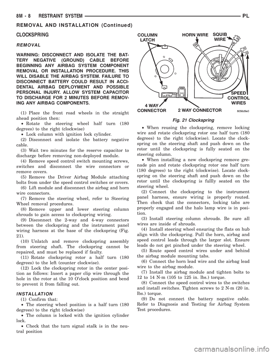
(9) Disconnect the 2-way and 4-way connectors
between the clockspring and the instrument panel
wiring harness at the base of the clockspring (Fig.
21).
(10) Unlatch and remove clockspring assembly
from steering shaft. The clockspring cannot be
repaired, and must be replaced if faulty.
(11) Rotate clockspring rotor a half turn (180
degrees) to the left (counter clockwise).
(12) Lock the clockspring rotor in the center posi-
tion as follows: Insert a paper clip wire through the
hole in the rotor at the 10 O'clock position and bend
to prevent it from falling out.
INSTALLATION
(1) Confirm that:
²The steering wheel position is a half turn (180
degrees) to the right (clockwise)
²The column is locked with the ignition cylinder
lock.
²Check that the turn signal stalk is in the neu-
tral position²When reusing the clockspring, remove locking
wire and rotate clockspring rotor one half turn (180
degrees) to the right (clockwise). Locate the clock-
spring on the steering shaft and push down on the
rotor until the clockspring is fully seated on the
steering column.
²When installing a new clockspring remove gre-
nade pin and rotate clockspring rotor one half turn
(180 degrees) to the right (clockwise). Locate clock-
spring on the steering shaft and push down on the
rotor until the clockspring is fullly seated on the
steering wheel.
(2) Connect the clockspring to the instrument
panel harness, ensure wiring is properly routed.
Then check that the connectors, locking tabs are
properly engaged and the halo lamp wire is in posi-
tion.
(3) Install steering column shrouds. Be sure all
wires are inside of shrouds.
(4) Install steering wheel ensuring the flats on hub
align with the clockspring. Pull the horn, airbag and
speed control leads through the larger slot. Ensure
leads do not get pinched under the steering wheel.
(5) Route speed control wires under and behind
the airbag module mounting tabs.
(6) Connect the horn lead wire and the airbag lead
wire to the airbag module.
(7) Install the airbag module and tighten bolts to
12 to 14 N´m (105 to 125 in. lbs.) torque.
(8) Connect the speed control wires to the switches
and install switches. Tighten screws to 2 N´m (20 in.
lbs.) torque.
(9) Do not connect the battery negative cable.
Refer to Diagnosis and Testing for Airbag System
Test procedures.
Fig. 21 Clockspring
8M - 8 RESTRAINT SYSTEMPL
REMOVAL AND INSTALLATION (Continued)
Page 360 of 1200
DRIVER AIRBAG MODULE
REMOVAL
WARNING: DISCONNECT AND ISOLATE THE BAT-
TERY NEGATIVE (GROUND) CABLE BEFORE
BEGINNING ANY AIRBAG SYSTEM COMPONENT
REMOVAL OR INSTALLATION PROCEDURE. THIS
WILL DISABLE THE AIRBAG SYSTEM. FAILURE TO
DISCONNECT BATTERY COULD RESULT IN ACCI-
DENTAL AIRBAG DEPLOYMENT AND POSSIBLE
PERSONAL INJURY. ALLOW SYSTEM CAPACITOR
TO DISCHARGE FOR 2 MINUTES BEFORE REMOV-
ING ANY AIRBAG COMPONENTS.
When removing a deployed module, rubber gloves,
eye protection and long sleeved shirt should be worn,
as there may be deposits on the surface which could
irritate the skin and eyes.
(1) Disconnect and isolate the battery negative
cable.
(2) Remove speed control switches or covers from
steering wheel armature and disconnect the wires.
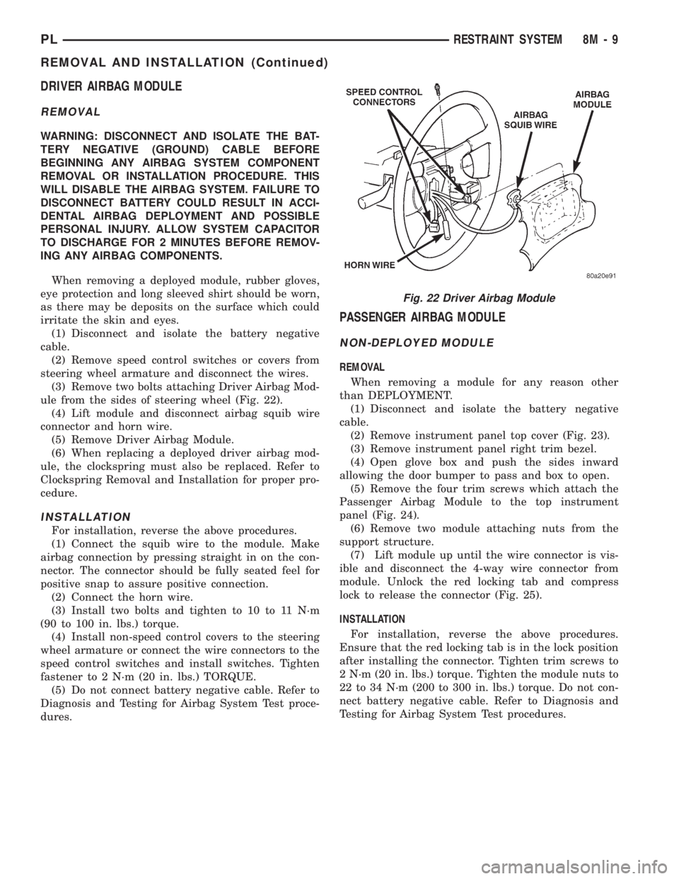
(3) Remove two bolts attaching Driver Airbag Mod-
ule from the sides of steering wheel (Fig. 22).
(4) Lift module and disconnect airbag squib wire
connector and horn wire.
(5) Remove Driver Airbag Module.
(6) When replacing a deployed driver airbag mod-
ule, the clockspring must also be replaced. Refer to
Clockspring Removal and Installation for proper pro-
cedure.
INSTALLATION
For installation, reverse the above procedures.
(1) Connect the squib wire to the module. Make
airbag connection by pressing straight in on the con-
nector. The connector should be fully seated feel for
positive snap to assure positive connection.
(2) Connect the horn wire.
(3) Install two bolts and tighten to 10 to 11 N´m
(90 to 100 in. lbs.) torque.
(4) Install non-speed control covers to the steering
wheel armature or connect the wire connectors to the
speed control switches and install switches. Tighten
fastener to 2 N´m (20 in. lbs.) TORQUE.
(5) Do not connect battery negative cable. Refer to
Diagnosis and Testing for Airbag System Test proce-
dures.
PASSENGER AIRBAG MODULE
NON-DEPLOYED MODULE
REMOVAL
When removing a module for any reason other
than DEPLOYMENT.
(1) Disconnect and isolate the battery negative
cable.
(2) Remove instrument panel top cover (Fig. 23).
(3) Remove instrument panel right trim bezel.
(4) Open glove box and push the sides inward
allowing the door bumper to pass and box to open.
(5) Remove the four trim screws which attach the
Passenger Airbag Module to the top instrument
panel (Fig. 24).
(6) Remove two module attaching nuts from the
support structure.
(7) Lift module up until the wire connector is vis-
ible and disconnect the 4-way wire connector from
module. Unlock the red locking tab and compress
lock to release the connector (Fig. 25).
INSTALLATION
For installation, reverse the above procedures.
Ensure that the red locking tab is in the lock position
after installing the connector. Tighten trim screws to
2 N´m (20 in. lbs.) torque. Tighten the module nuts to
22 to 34 N´m (200 to 300 in. lbs.) torque. Do not con-
nect battery negative cable. Refer to Diagnosis and
Testing for Airbag System Test procedures.
Fig. 22 Driver Airbag Module
PLRESTRAINT SYSTEM 8M - 9
REMOVAL AND INSTALLATION (Continued)
Page 361 of 1200
DEPLOYED MODULE
REMOVAL
When removing a deployed module, rubber gloves,
eye protection, and a long-sleeved shirt should beworn, as there may be deposits on the surface which
could irritate the skin and eyes.
(1) Disconnect and isolate the battery negative
cable.
(2) Roll/fold airbag towards instrument panel.
(3) Close door over folded airbag and tape door
closed.
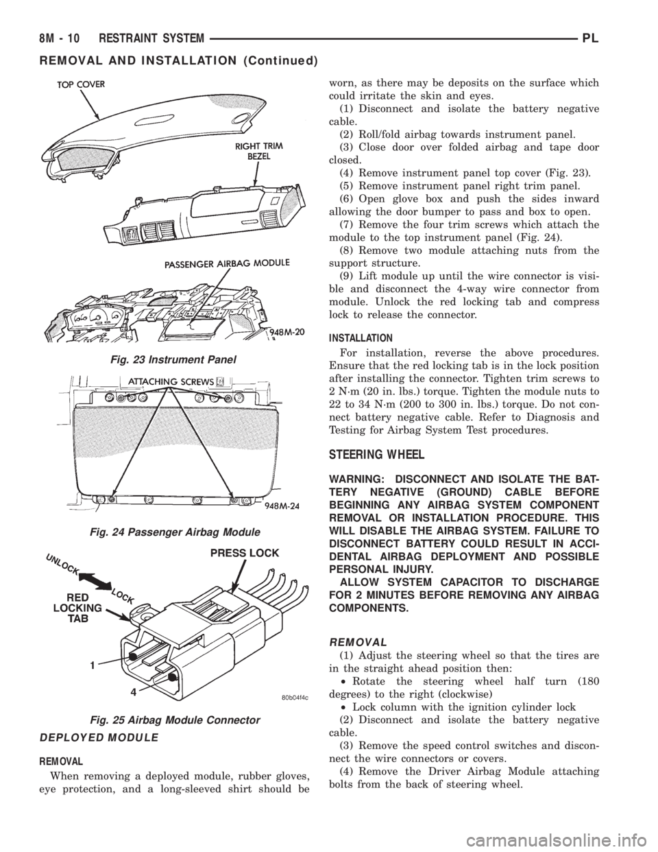
(4) Remove instrument panel top cover (Fig. 23).
(5) Remove instrument panel right trim panel.
(6) Open glove box and push the sides inward
allowing the door bumper to pass and box to open.
(7) Remove the four trim screws which attach the
module to the top instrument panel (Fig. 24).
(8) Remove two module attaching nuts from the
support structure.
(9) Lift module up until the wire connector is visi-
ble and disconnect the 4-way wire connector from
module. Unlock the red locking tab and compress
lock to release the connector.
INSTALLATION
For installation, reverse the above procedures.
Ensure that the red locking tab is in the lock position
after installing the connector. Tighten trim screws to
2 N´m (20 in. lbs.) torque. Tighten the module nuts to
22 to 34 N´m (200 to 300 in. lbs.) torque. Do not con-
nect battery negative cable. Refer to Diagnosis and
Testing for Airbag System Test procedures.
STEERING WHEEL
WARNING: DISCONNECT AND ISOLATE THE BAT-
TERY NEGATIVE (GROUND) CABLE BEFORE
BEGINNING ANY AIRBAG SYSTEM COMPONENT
REMOVAL OR INSTALLATION PROCEDURE. THIS
WILL DISABLE THE AIRBAG SYSTEM. FAILURE TO
DISCONNECT BATTERY COULD RESULT IN ACCI-
DENTAL AIRBAG DEPLOYMENT AND POSSIBLE
PERSONAL INJURY.
ALLOW SYSTEM CAPACITOR TO DISCHARGE
FOR 2 MINUTES BEFORE REMOVING ANY AIRBAG
COMPONENTS.
REMOVAL
(1) Adjust the steering wheel so that the tires are
in the straight ahead position then:
²Rotate the steering wheel half turn (180
degrees) to the right (clockwise)
²Lock column with the ignition cylinder lock
(2) Disconnect and isolate the battery negative
cable.
(3) Remove the speed control switches and discon-
nect the wire connectors or covers.
(4) Remove the Driver Airbag Module attaching
bolts from the back of steering wheel.
Fig. 23 Instrument Panel
Fig. 24 Passenger Airbag Module
Fig. 25 Airbag Module Connector
8M - 10 RESTRAINT SYSTEMPL
REMOVAL AND INSTALLATION (Continued)
Page 364 of 1200
ELECTRICALLY HEATED SYSTEMS
CONTENTS
page page
DESCRIPTION AND OPERATION
INTRODUCTION......................... 1
REAR WINDOW DEFOGGER SWITCH........ 1
DIAGNOSIS AND TESTING
DEFOGGER SYSTEM..................... 1GRID LINES............................ 2
REAR WINDOW DEFOGGER SWITCH........ 2
SERVICE PROCEDURES
GRID LINE AND TERMINAL REPAIR......... 3
DESCRIPTION AND OPERATION
INTRODUCTION
For proper operation of the Rear Window Defogger
system refer to the Owner's Manual.
The system consists of a rear glass with two verti-
cal bus bars and a series of electrically connected
grid lines fired on the inside surface. A control switch
and a timer relay combined into a single assembly is
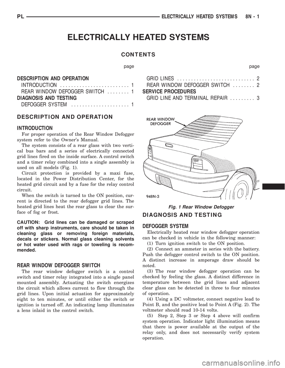
used on all models (Fig. 1).
Circuit protection is provided by a maxi fuse,
located in the Power Distribution Center, for the
heated grid circuit and by a fuse for the relay control
circuit.
When the switch is turned to the ON position, cur-
rent is directed to the rear defogger grid lines. The
heated grid lines heat the rear glass to clear the sur-
face of fog or frost.
CAUTION: Grid lines can be damaged or scraped
off with sharp instruments, care should be taken in
cleaning glass or removing foreign materials,
decals or stickers. Normal glass cleaning solvents
or hot water used with rags or toweling is recom-
mended.
REAR WINDOW DEFOGGER SWITCH
The rear window defogger switch is a control
switch and timer relay integrated into a single panel
mounted assembly. Actuating the switch energizes
the circuit which allows current to flow through the
grid lines. Upon initial actuation for approximately
eight to ten minutes, or until either the switch or
ignition is turned off. An indicating lamp illuminates
a lens inlaid in the control switch.
DIAGNOSIS AND TESTING
DEFOGGER SYSTEM
Electrically heated rear window defogger operation
can be checked in vehicle in the following manner:
(1) Turn ignition switch to the ON position.
(2) Connect an ammeter in series with the battery.
Push the defogger control switch to the ON position.
A distinct increase in amperage draw should be
noted.
(3) The rear window defogger operation can be
checked by feeling the glass. A distinct difference in
temperature between the grid lines and adjacent
clear glass can be detected in three to four minutes
of operation.
(4) Using a DC voltmeter, connect negative lead to
Point B, and the positive lead to Point A (Fig. 2). The
voltmeter should read 10-14 volts.
(5) Step 2, Step 3 or Step 4 above will confirm
system operation. Indicator light illumination means
that there is power available at the output of the
relay only, and does not necessarily verify system
operation.
Fig. 1 Rear Window Defogger
PLELECTRICALLY HEATED SYSTEMS 8N - 1