hood release DODGE NEON 1999 Service Repair Manual
[x] Cancel search | Manufacturer: DODGE, Model Year: 1999, Model line: NEON, Model: DODGE NEON 1999Pages: 1200, PDF Size: 35.29 MB
Page 218 of 1200
BATTERY
CONTENTS
page page
GENERAL INFORMATION
INTRODUCTION......................... 1
DESCRIPTION AND OPERATION
BATTERY IGNITION OFF DRAW (IOD)........ 1
CHARGING TIME REQUIRED............... 1
DIAGNOSIS AND TESTING
BATTERY BUILT-IN TEST INDICATOR........ 2
BATTERY IGNITION OFF DRAW (IOD)........ 3
BATTERY LOAD TEST..................... 5
BATTERY OPEN CIRCUIT VOLTAGE TEST..... 6
BATTERY TEMPERATURE SENSOR.......... 6
SERVICE PROCEDURES
BATTERY CHARGING..................... 6CHARGING COMPLETELY DISCHARGED
BATTERY............................. 7
VISUAL INSPECTION..................... 7
REMOVAL AND INSTALLATION
BATTERY TRAY.......................... 9
BATTERY............................... 8
FRESH AIR INLET TUBE REMOVAL.......... 9
SPECIFICATIONS
BATTERY SPECIFICATIONS............... 10
TORQUE.............................. 10
GENERAL INFORMATION
INTRODUCTION
The battery stores, stabilizes, and delivers electri-
cal current to operate various electrical systems in
the vehicle. The determination of whether a battery
is good or bad is made by its ability to accept a
charge. It also must supply high-amperage current
for a long enough period to be able to start the vehi-
cle. The capability of the battery to store electrical
current comes from a chemical reaction. This reac-
tion takes place between the sulfuric acid solution
(electrolyte) and the lead +/- plates in each cell of the
battery. As the battery discharges, the plates react
with the acid from the electrolyte. When the charging
system charges the battery, the water is converted to
sulfuric acid in the battery. The concentration of acid
in the electrolyte is measured as specific gravity
using a hydrometer. The original equipment (OE)
battery is equipped with a hydrometer (test indica-
tor) built into the battery cover. The specific gravity
indicates the battery's state-of-charge. The OE bat-
tery is sealed and water cannot be added.
The battery is vented to release gases that are cre-
ated when the battery is being charged and dis-
charged. The battery top, posts, and terminals should
be cleaned when other under hood maintenance is
performed.
When the electrolyte level is below the top of the
plates, Yellow/Clear in the test Indicator, the battery
must be replaced. The battery must be completely
charged, and the battery top, posts, and cable clampsmust be cleaned before diagnostic procedures are per-
formed.DESCRIPTION AND OPERATION
BATTERY IGNITION OFF DRAW (IOD)
A completely normal vehicle will have a small
amount of current drain on the battery with the key
out of the ignition. It can range from 4 to 10 milli-
amperes after all the modules time out. If a vehicle
will not be operated for approximately a 20 days, the
IOD fuse should be disconnected to minimize the
vehicle electrical drain on the battery. The IOD fuse
is located in the Power Distribution Center (PDC).
Refer to the PDC to locate the cover proper fuse.
CHARGING TIME REQUIRED
WARNING: NEVER EXCEED 20 AMPS WHEN
CHARGING A COLD -1ÉC (30ÉF) BATTERY. PER-
SONAL INJURY MAY RESULT.
The time required to charge a battery will vary
depending upon the following factors.
SIZE OF BATTERY
A completely discharged large heavy-duty battery
may require more recharging time than a completely
discharged small capacity battery. Refer to Battery
Charging Timetable for proper charging times.
PLBATTERY 8A - 1
Page 321 of 1200
WINDSHIELD WASHER SYSTEM
INDEX
page page
DESCRIPTION AND OPERATION
WASHER NOZZLE........................ 8
DIAGNOSIS AND TESTING
WINDSHIELD WASHERS................... 8REMOVAL AND INSTALLATION
WASHER NOZZLE........................ 9
WASHER RESERVOIR PUMP.............. 10
WASHER RESERVOIR..................... 9
DESCRIPTION AND OPERATION
WASHER NOZZLE
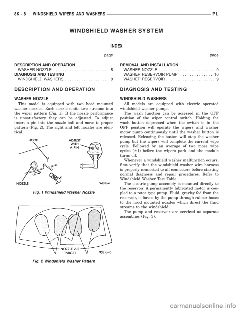
This model is equipped with two hood mounted
washer nozzles. Each nozzle emits two streams into
the wiper pattern (Fig. 1). If the nozzle performance
is unsatisfactory they can be adjusted. To adjust
insert a pin into the nozzle ball and move to proper
pattern (Fig. 2). The right and left nozzles are iden-
tical.
DIAGNOSIS AND TESTING
WINDSHIELD WASHERS
All models are equipped with electric operated
windshield washer pumps.
The wash function can be accessed in the OFF
position of the wiper control switch. Holding the
wash button depressed when the switch is in the
OFF position will operate the wipers and washer
motor pump continuously until the washer button is
released. Releasing the button will stop the washer
pump but the wipers will complete the current wipe
cycle. Followed by an average of two more wipe
cycles (61) before the wipers park and the module
turns off.
Whenever a windshield washer malfunction occurs,
first verify that the windshield washer wire harness
is properly connected to all connectors before starting
normal diagnosis and repair procedures. Refer to
Windshield Washer Test Table.
The electric pump assembly is mounted directly to
the reservoir. A permanently lubricated motor is cou-
pled to a rotor type pump. Fluid, gravity fed from the
reservoir, is forced by the pump through rubber hoses
to the hood mounted nozzles which direct the fluid
streams to the windshield.
The pump and reservoir are serviced as separate
assemblies (Fig. 3).
Fig. 1 Windshield Washer Nozzle
Fig. 2 Windshield Washer Pattern
8K - 8 WINDSHIELD WIPERS AND WASHERSPL
Page 335 of 1200
LAMP BULB SERVICE
INDEX
page page
REMOVAL AND INSTALLATION
CENTER HIGH MOUNTED STOP LAMP BULB . . . 7
DOME LAMP BULB....................... 8
FOG LAMP BULB......................... 6
FRONT SIDE MARKER LAMP BULB.......... 7
HEADLAMP BULB........................ 6
LICENSE PLATE LAMP BULB............... 8PARK AND TURN SIGNAL LAMP BULB........ 6
REAR CARGO LAMP BULB................. 8
TAIL, STOP, BACK-UP AND TURN SIGNAL
LAMP BULB........................... 7
UNDERHOOD LAMP BULB................. 8
VISOR VANITY LAMP BULB................. 8
REMOVAL AND INSTALLATION
HEADLAMP BULB
REMOVAL
(1) Release hood latch and open hood.
(2) Disengage wire connector from headlamp bulb
connector.
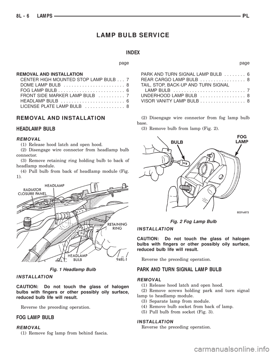
(3) Remove retaining ring holding bulb to back of
headlamp module.
(4) Pull bulb from back of headlamp module (Fig.
1).
INSTALLATION
CAUTION: Do not touch the glass of halogen
bulbs with fingers or other possibly oily surface,
reduced bulb life will result.
Reverse the preceding operation.
FOG LAMP BULB
REMOVAL
(1) Remove fog lamp from behind fascia.(2) Disengage wire connector from fog lamp bulb
base.
(3) Remove bulb from lamp (Fig. 2).
INSTALLATION
CAUTION: Do not touch the glass of halogen
bulbs with fingers or other possibly oily surface,
reduced bulb life will result.
Reverse the preceding operation.
PARK AND TURN SIGNAL LAMP BULB
REMOVAL
(1) Release hood latch and open hood.
(2) Remove screws holding park and turn signal
lamp to headlamp module.
(3) Separate lamp from module.
(4) Remove bulb socket from back of lamp.
(5) Pull bulb from socket (Fig. 3).
INSTALLATION
Reverse the preceding operation.
Fig. 1 Headlamp Bulb
Fig. 2 Fog Lamp Bulb
8L - 6 LAMPSPL
Page 338 of 1200
LAMP SERVICE
INDEX
page page
REMOVAL AND INSTALLATION
CENTER HIGH MOUNTED STOP LAMP
(CHMSL)............................. 10
DOME LAMP........................... 11
FOG LAMP.............................. 9
FRONT SIDE MARKER LAMP.............. 10
HEADLAMP MODULE..................... 9LICENSE PLATE LAMP................... 11
PARK AND TURN SIGNAL LAMP............. 9
REAR CARGO LAMP..................... 11
TAIL, STOP AND TURN SIGNAL LAMP........ 10
UNDERHOOD LAMP..................... 11
VISOR VANITY LAMP..................... 11
REMOVAL AND INSTALLATION
HEADLAMP MODULE
REMOVAL
(1) Release hood latch and open hood.
(2) From behind bumper fascia, remove bolt hold-
ing outboard end of module to fender and closure
panel.
(3) Loosen bolts holding inboard end of module to
radiator closure panel and remove bolt to grille.
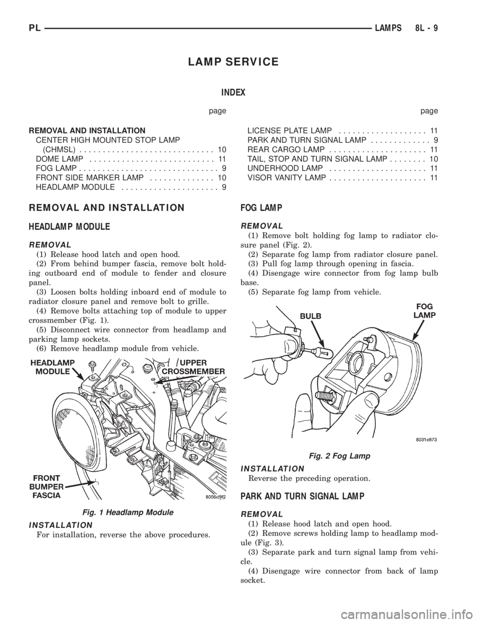
(4) Remove bolts attaching top of module to upper
crossmember (Fig. 1).
(5) Disconnect wire connector from headlamp and
parking lamp sockets.
(6) Remove headlamp module from vehicle.
INSTALLATION
For installation, reverse the above procedures.
FOG LAMP
REMOVAL
(1) Remove bolt holding fog lamp to radiator clo-
sure panel (Fig. 2).
(2) Separate fog lamp from radiator closure panel.
(3) Pull fog lamp through opening in fascia.
(4) Disengage wire connector from fog lamp bulb
base.
(5) Separate fog lamp from vehicle.
INSTALLATION
Reverse the preceding operation.
PARK AND TURN SIGNAL LAMP
REMOVAL
(1) Release hood latch and open hood.
(2) Remove screws holding lamp to headlamp mod-
ule (Fig. 3).
(3) Separate park and turn signal lamp from vehi-
cle.
(4) Disengage wire connector from back of lamp
socket.
Fig. 1 Headlamp Module
Fig. 2 Fog Lamp
PLLAMPS 8L - 9
Page 345 of 1200
LAMP BULB SERVICE
INDEX
page page
REMOVAL AND INSTALLATION
CITYLIGHT LAMP BULB.................... 3
FOG LAMP BULB......................... 3FRONT TURN SIGNAL LAMP BULB........... 2
HEADLAMP BULB........................ 2
SIDE REPEATER LAMP BULB............... 4
REMOVAL AND INSTALLATION
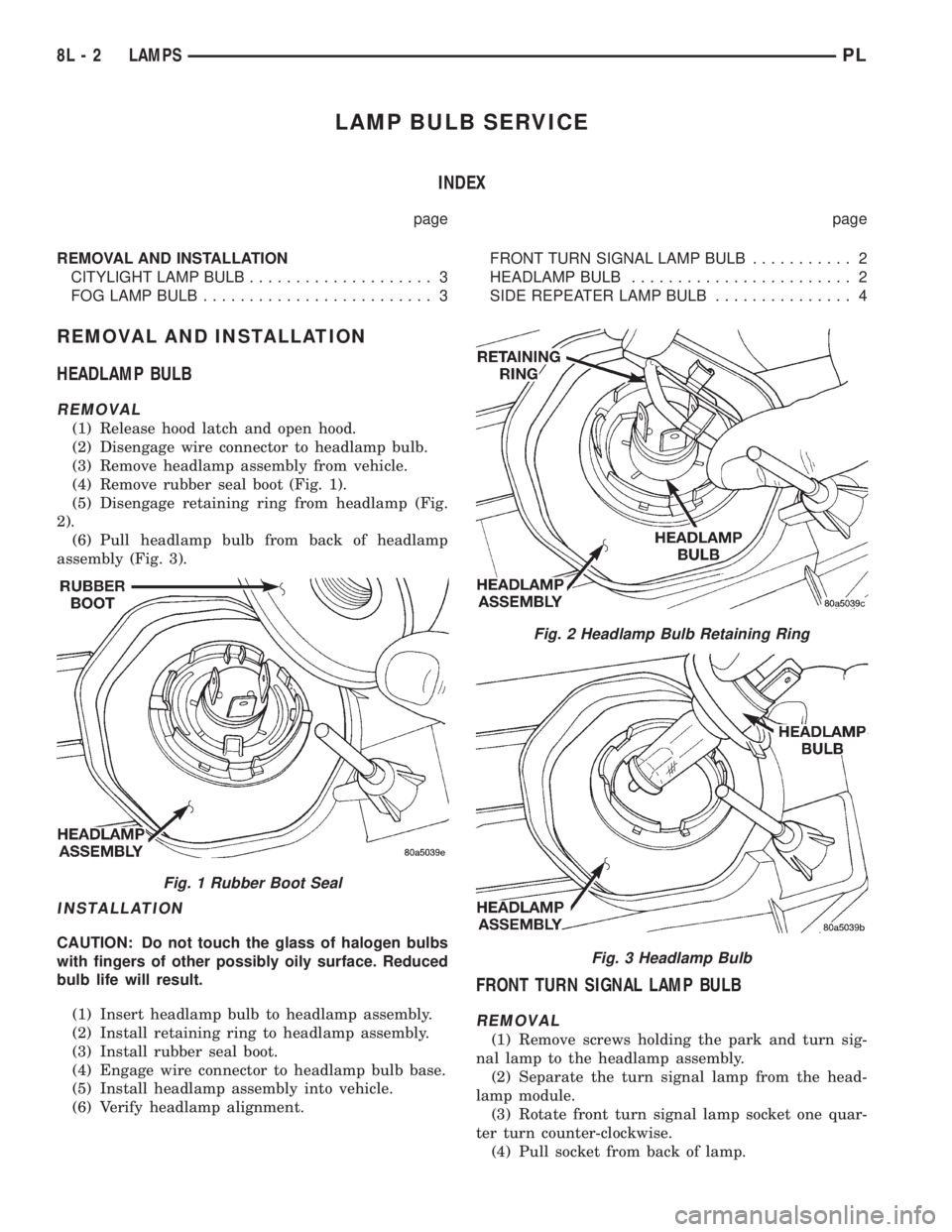
HEADLAMP BULB
REMOVAL
(1) Release hood latch and open hood.
(2) Disengage wire connector to headlamp bulb.
(3) Remove headlamp assembly from vehicle.
(4) Remove rubber seal boot (Fig. 1).
(5) Disengage retaining ring from headlamp (Fig.
2).
(6) Pull headlamp bulb from back of headlamp
assembly (Fig. 3).
INSTALLATION
CAUTION: Do not touch the glass of halogen bulbs
with fingers of other possibly oily surface. Reduced
bulb life will result.
(1) Insert headlamp bulb to headlamp assembly.
(2) Install retaining ring to headlamp assembly.
(3) Install rubber seal boot.
(4) Engage wire connector to headlamp bulb base.
(5) Install headlamp assembly into vehicle.
(6) Verify headlamp alignment.
FRONT TURN SIGNAL LAMP BULB
REMOVAL
(1) Remove screws holding the park and turn sig-
nal lamp to the headlamp assembly.
(2) Separate the turn signal lamp from the head-
lamp module.
(3) Rotate front turn signal lamp socket one quar-
ter turn counter-clockwise.
(4) Pull socket from back of lamp.
Fig. 1 Rubber Boot Seal
Fig. 2 Headlamp Bulb Retaining Ring
Fig. 3 Headlamp Bulb
8L - 2 LAMPSPL
Page 348 of 1200
LAMP SERVICE
INDEX
page page
GENERAL INFORMATION
HEADLAMP DIMMER SWITCH............... 5
HEADLAMP SWITCH...................... 5
REMOVAL AND INSTALLATION
FOG LAMP.............................. 6HEADLAMP ASSEMBLY.................... 5
HEADLAMP LEVELING MOTOR.............. 6
SIDE REPEATER LAMP.................... 6
GENERAL INFORMATION
HEADLAMP SWITCH
Service procedures for the headlamp switch can be
found in Group 8E, Instrument Panel and Gauges.
More information can be found in Group 8W, Wiring
Diagrams.
HEADLAMP DIMMER SWITCH
The headlamp dimmer switch is incorporated into
the multi-function (turn signal) switch. Proper proce-
dures can be found in Group 8J, Turn Signal and
Flashers. More information can be found in Group
8W, Wiring Diagrams.
REMOVAL AND INSTALLATION
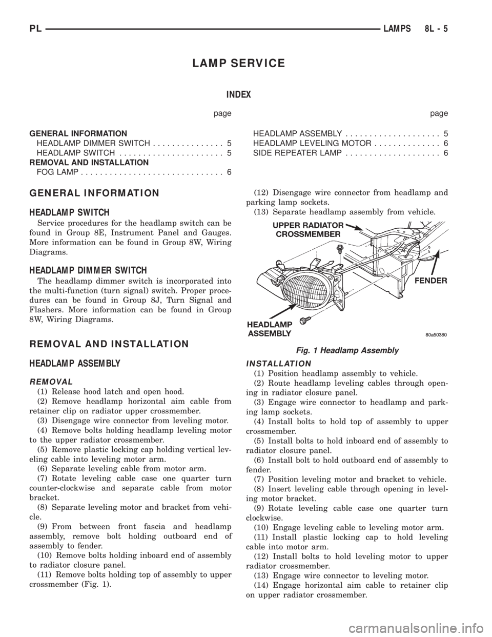
HEADLAMP ASSEMBLY
REMOVAL
(1) Release hood latch and open hood.
(2) Remove headlamp horizontal aim cable from
retainer clip on radiator upper crossmember.
(3) Disengage wire connector from leveling motor.
(4) Remove bolts holding headlamp leveling motor
to the upper radiator crossmember.
(5) Remove plastic locking cap holding vertical lev-
eling cable into leveling motor arm.
(6) Separate leveling cable from motor arm.
(7) Rotate leveling cable case one quarter turn
counter-clockwise and separate cable from motor
bracket.
(8) Separate leveling motor and bracket from vehi-
cle.
(9) From between front fascia and headlamp
assembly, remove bolt holding outboard end of
assembly to fender.
(10) Remove bolts holding inboard end of assembly
to radiator closure panel.
(11) Remove bolts holding top of assembly to upper
crossmember (Fig. 1).(12) Disengage wire connector from headlamp and
parking lamp sockets.
(13) Separate headlamp assembly from vehicle.
INSTALLATION
(1) Position headlamp assembly to vehicle.
(2) Route headlamp leveling cables through open-
ing in radiator closure panel.
(3) Engage wire connector to headlamp and park-
ing lamp sockets.
(4) Install bolts to hold top of assembly to upper
crossmember.
(5) Install bolts to hold inboard end of assembly to
radiator closure panel.
(6) Install bolt to hold outboard end of assembly to
fender.
(7) Position leveling motor and bracket to vehicle.
(8) Insert leveling cable through opening in level-
ing motor bracket.
(9) Rotate leveling cable case one quarter turn
clockwise.
(10) Engage leveling cable to leveling motor arm.
(11) Install plastic locking cap to hold leveling
cable into motor arm.
(12) Install bolts to hold leveling motor to upper
radiator crossmember.
(13) Engage wire connector to leveling motor.
(14) Engage horizontal aim cable to retainer clip
on upper radiator crossmember.
Fig. 1 Headlamp Assembly
PLLAMPS 8L - 5
Page 1083 of 1200
BODY COMPONENTS
INDEX
page page
DIAGNOSIS AND TESTING
WATER LEAKS.......................... 3
WIND NOISE............................ 4
SERVICE PROCEDURES
HEAT STAKING.......................... 4
REMOVAL AND INSTALLATION
WINDOW REGULATORÐ4 DOOR........... 36
A-PILLAR TRIM.......................... 4
B-PILLAR APPLIQUEÐ2 DOOR.............. 5
B-PILLAR APPLIQUEÐ4 DOOR.............. 5
B-PILLAR TRIMÐ4 DOOR.................. 6
B-PILLAR WEATHERSTRIP CHANNEL......... 6
BODY VENT............................. 6
CARPET............................... 7
CHILD RESTRAINT SEAT BACK............. 8
CHILD SEAT MODULE..................... 8
COWL COVER........................... 7
DOOR HINGE........................... 9
DOOR LOCK CYLINDER.................. 10
DOOR OPENING TRIM WELT.............. 10
DOOR SILL TRIM........................ 10
DOOR................................. 9
FLOOR CONSOLE LATCH................. 11
FLOOR CONSOLE....................... 11
FRONT DOOR CHECK STOP............... 11
FRONT DOOR GLASSÐ2 DOOR............ 12
FRONT DOOR GLASSÐ4 DOOR............ 13
FRONT DOOR INNER BELT WEATHERSTRIP . . 13
FRONT DOOR LATCH STRIKER............ 14
FRONT DOOR LATCH.................... 13
FRONT DOOR OUTER BELT WEATHERSTRIP . 14
FRONT DOOR OUTSIDE HANDLE........... 14
FRONT DOOR TRIM PANEL................ 14
FRONT DOOR WATER SHIELD............. 16
FRONT DOOR WEATHERSTRIP............ 16
FRONT OUTBOARD SEAT BELT............ 17
FRONT SEAT BELT BUCKLE............... 18
FRONT SEAT BELT RETRACTOR........... 18
FRONT SEAT........................... 17
FRONT SHOULDER BELT ADJUSTER........ 18
FRONT VERTICAL GUIDE BAR............. 18
GRILLE............................... 19
HEADLINING........................... 19
HOOD HINGE.......................... 20
HOOD LATCH.......................... 21
HOOD RELEASE CABLE.................. 21
HOOD................................ 20
LOCK BUTTON BELL-CRANK.............. 21
LOWER QUARTER TRIMÐ4 DOOR.......... 22PARCEL SHELF TRIM.................... 22
QUARTER TRIM PANELÐ2 DOOR........... 22
REAR DOOR GLASS..................... 23
REAR DOOR INNER BELT WEATHERSTRIP . . . 23
REAR DOOR INTERLOCK LATCH STRIKER . . . 24
REAR DOOR LATCH STRIKER............. 24
REAR DOOR LATCH..................... 24
REAR DOOR LOCK BELL CRANK........... 24
REAR DOOR OUTER BELT WEATHERSTRIP . . 25
REAR DOOR TRIM....................... 25
REAR DOOR WINDOW REGULATOR........ 25
REAR SEAT BACK....................... 26
REAR SEAT BELT BUCKLE................ 26
REAR SEAT BELT RETRACTOR............ 26
REAR SEAT CUSHION.................... 26
REAR SPOILER......................... 27
REAR VERTICAL GUIDE BAR.............. 27
ROOF APERTURE (RAP) MOLDING.......... 28
ROOF RACK CROSS RAILS............... 28
ROOF RACK........................... 28
ROOF RAIL WEATHER-STRIP FOUR DOOR . . . 29
ROOF RAIL WEATHER-STRIP ± TWO DOOR . . . 29
SIDE COWL TRIM....................... 30
SIDE VIEW MIRROR STANCHION........... 31
SIDE VIEW MIRROR TRIM COVER.......... 31
SIDE VIEW MIRROR..................... 30
SUN VISOR SUPPORT................... 31
SUN VISOR............................ 31
TRUNK CARPET........................ 31
TRUNK LATCH STRIKER.................. 32
TRUNK LATCH.......................... 32
TRUNK LID LIFT SPRINGS................ 33
TRUNK LID............................ 32
TRUNK LOCK CYLINDER................. 33
TRUNK TRIM PANEL..................... 34
TRUNK WEATHERSTRIP.................. 34
UPPER QUARTER TRIMÐ4 DOOR.......... 34
WINDOW INNERBELT STABILIZER.......... 34
WINDOW REGULATORÐ2 DOOR........... 35
ADJUSTMENTS
FRONT DOOR GLASS ADJUSTMENT........ 37
FRONT DOOR LATCH ADJUSTMENT........ 38
REAR DOOR GLASS ADJUSTMENT......... 38
REAR DOOR LATCH ADJUSTMENT.......... 39
SPECIFICATIONS
BODY LUBRICATION SPECIFICATIONS....... 39
SPECIAL TOOLS
BODY................................. 40
23 - 2 BODYPL
Page 1088 of 1200
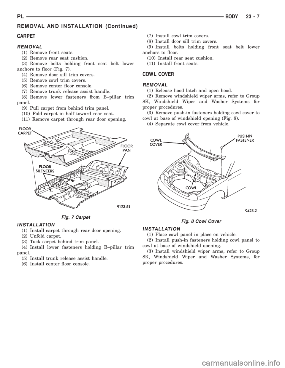
CARPET
REMOVAL
(1) Remove front seats.
(2) Remove rear seat cushion.
(3) Remove bolts holding front seat belt lower
anchors to floor (Fig. 7).
(4) Remove door sill trim covers.
(5) Remove cowl trim covers.
(6) Remove center floor console.
(7) Remove trunk release assist handle.
(8) Remove lower fasteners from B±pillar trim
panel.
(9) Pull carpet from behind trim panel.
(10) Fold carpet in half toward rear seat.
(11) Remove carpet through rear door opening.
INSTALLATION
(1) Install carpet through rear door opening.
(2) Unfold carpet.
(3) Tuck carpet behind trim panel.
(4) Install lower fasteners holding B±pillar trim
panel.
(5) Install trunk release assist handle.
(6) Install center floor console.(7) Install cowl trim covers.
(8) Install door sill trim covers.
(9) Install bolts holding front seat belt lower
anchors to floor.
(10) Install rear seat cushion.
(11) Install front seats.
COWL COVER
REMOVAL
(1) Release hood latch and open hood.
(2) Remove windshield wiper arms, refer to Group
8K, Windshield Wiper and Washer Systems for
proper procedures.
(3) Remove push-in fasteners holding cowl cover to
cowl at base of windshield opening (Fig. 8).
(4) Separate cowl cover from vehicle.
INSTALLATION
(1) Place cowl panel in place on vehicle.
(2) Install push-in fasteners holding cowl panel to
cowl at base of windshield opening.
(3) Install windshield wiper arms, refer to Group
8K, Windshield Wiper and Washer Systems, for
proper procedures.
Fig. 7 CarpetFig. 8 Cowl Cover
PLBODY 23 - 7
REMOVAL AND INSTALLATION (Continued)
Page 1100 of 1200
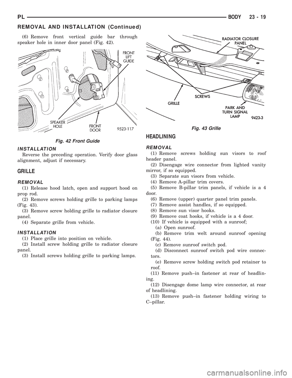
(6) Remove front vertical guide bar through
speaker hole in inner door panel (Fig. 42).
INSTALLATION
Reverse the preceding operation. Verify door glass
alignment, adjust if necessary.
GRILLE
REMOVAL
(1) Release hood latch, open and support hood on
prop rod.
(2) Remove screws holding grille to parking lamps
(Fig. 43).
(3) Remove screw holding grille to radiator closure
panel.
(4) Separate grille from vehicle.
INSTALLATION
(1) Place grille into position on vehicle.
(2) Install screw holding grille to radiator closure
panel.
(3) Install screws holding grille to parking lamps.
HEADLINING
REMOVAL
(1) Remove screws holding sun visors to roof
header panel.
(2) Disengage wire connector from lighted vanity
mirror, if so equipped.
(3) Separate sun visors from vehicle.
(4) Remove A-pillar trim covers.
(5) Remove B-pillar trim panels, if vehicle is a 4
door.
(6) Remove (upper) quarter panel trim panels.
(7) Remove assist handles, if so equipped.
(8) Remove sun visor hooks.
(9) Remove coat hooks, if vehicle is a 4 door.
(10) If vehicle is equipped with a sunroof;
(a) Open sunroof.
(b) Remove trim welt around sunroof opening
(Fig. 44).
(c) Remove sunroof switch pod.
(d) Disconnect sunroof switch pod wire connec-
tors.
(e) Remove screw holding switch pod retainer to
roof.
(11) Remove push±in fastener at rear of headlin-
ing.
(12) Disengage dome lamp wire connector, at rear
of headlining.
(13) Remove push±in fastener holding wiring to
C±pillar.
Fig. 42 Front Guide
Fig. 43 Grille
PLBODY 23 - 19
REMOVAL AND INSTALLATION (Continued)
Page 1102 of 1200
(4) Remove bolts holding hood hinge to front
fender flange and separate hinge from vehicle. If nec-
essary, paint new hinge before installation.
INSTALLATION
(1) If necessary, paint new hinge before installa-
tion.
(2) Place hinge in position on vehicle.
(3) Install bolts to hold hood hinge to front fender
flange.
(4) Install bolts to hold hood to hinge.
(5) Align all marks and secure bolts. The hood
should be aligned to 4 mm (0.160 in.) gap to the front
fenders and flush across the top surfaces along fend-
ers. Shims can be added or removed under hood
hinge to achieve proper hood height.
(6) Remove support from under hood and verify
hood operation.
HOOD LATCH
REMOVAL
(1) Release hood latch and open hood.
(2) Support hood on prop rod.
(3) Remove grille.
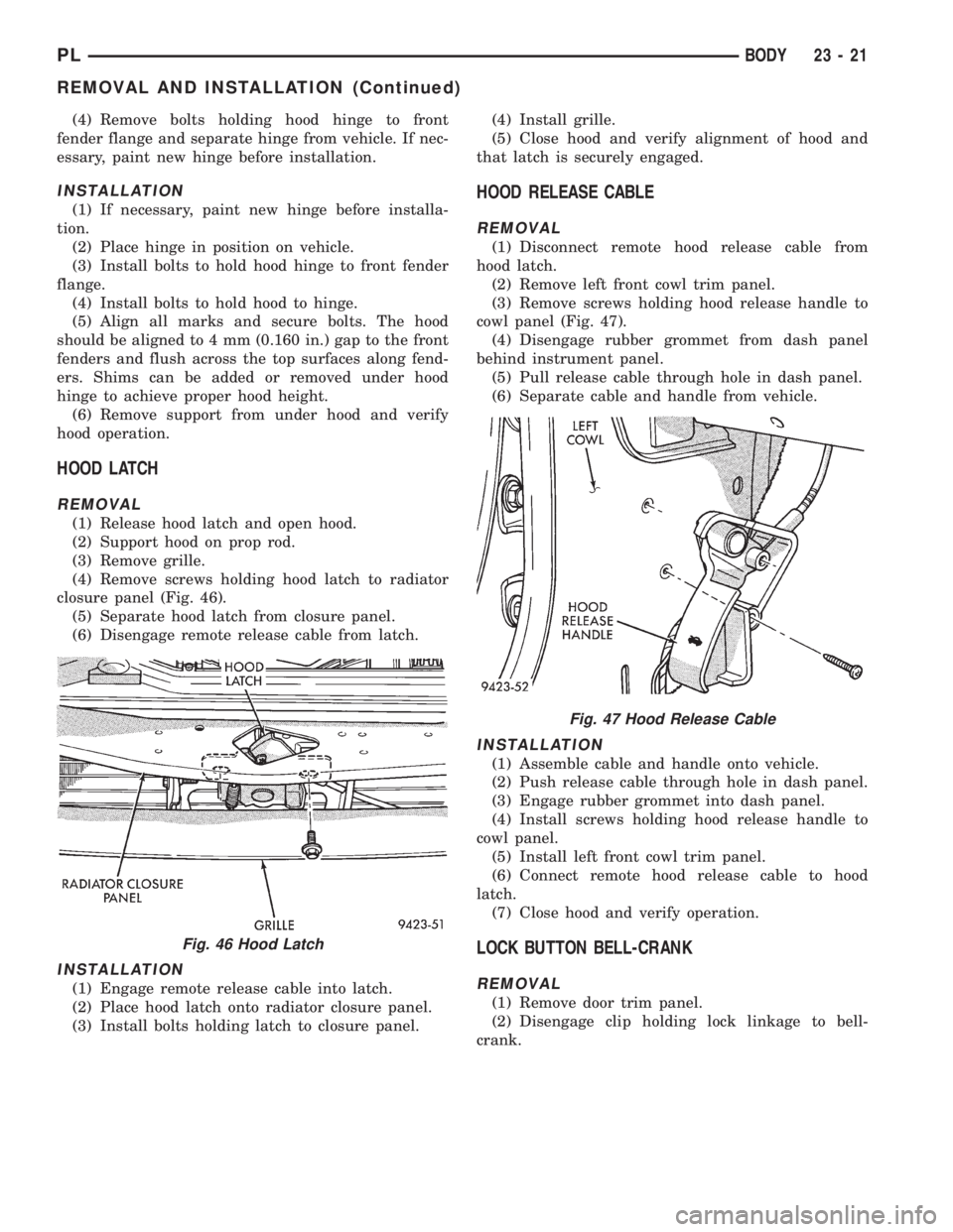
(4) Remove screws holding hood latch to radiator
closure panel (Fig. 46).
(5) Separate hood latch from closure panel.
(6) Disengage remote release cable from latch.
INSTALLATION
(1) Engage remote release cable into latch.
(2) Place hood latch onto radiator closure panel.
(3) Install bolts holding latch to closure panel.(4) Install grille.
(5) Close hood and verify alignment of hood and
that latch is securely engaged.
HOOD RELEASE CABLE
REMOVAL
(1) Disconnect remote hood release cable from
hood latch.
(2) Remove left front cowl trim panel.
(3) Remove screws holding hood release handle to
cowl panel (Fig. 47).
(4) Disengage rubber grommet from dash panel
behind instrument panel.
(5) Pull release cable through hole in dash panel.
(6) Separate cable and handle from vehicle.
INSTALLATION
(1) Assemble cable and handle onto vehicle.
(2) Push release cable through hole in dash panel.
(3) Engage rubber grommet into dash panel.
(4) Install screws holding hood release handle to
cowl panel.
(5) Install left front cowl trim panel.
(6) Connect remote hood release cable to hood
latch.
(7) Close hood and verify operation.
LOCK BUTTON BELL-CRANK
REMOVAL
(1) Remove door trim panel.
(2) Disengage clip holding lock linkage to bell-
crank.
Fig. 46 Hood Latch
Fig. 47 Hood Release Cable
PLBODY 23 - 21
REMOVAL AND INSTALLATION (Continued)