automatic transmission DODGE NEON 2000 Service Repair Manual
[x] Cancel search | Manufacturer: DODGE, Model Year: 2000, Model line: NEON, Model: DODGE NEON 2000Pages: 1285, PDF Size: 29.42 MB
Page 8 of 1285
JUMP STARTING, TOWING, AND HOISTING
TABLE OF CONTENTS
page page
DESCRIPTION AND OPERATION
JUMP STARTING PROCEDURE...............7
TOWING RECOMMENDATIONS...............7
HOISTING RECOMMENDATIONS.............7SERVICE PROCEDURES
JUMP STARTING PROCEDURE...............7
TOWING RECOMMENDATIONS...............8
HOISTING RECOMMENDATIONS.............9
DESCRIPTION AND OPERATION
JUMP STARTING PROCEDURE
Describes the procedure for starting a disable vehi-
cle.
TOWING RECOMMENDATIONS
Describes the recommended towing procedures.
HOISTING RECOMMENDATIONS
Describes the location of hoisting and jacking
points so that the vehicle can be lifted by a floor jack
or hoist.
SERVICE PROCEDURES
JUMP STARTING PROCEDURE
WARNING: REVIEW ALL SAFETY PRECAUTIONS
AND WARNINGS IN GROUP 8A, BATTERY/START-
ING/CHARGING SYSTEMS DIAGNOSTICS. DO NOT
JUMP START A FROZEN BATTERY, PERSONAL
INJURY CAN RESULT. DO NOT JUMP START WHEN
MAINTENANCE FREE BATTERY INDICATOR DOT IS
YELLOW OR BRIGHT COLOR. DO NOT JUMP
START A VEHICLE WHEN THE BATTERY FLUID IS
BELOW THE TOP OF LEAD PLATES. DO NOT
ALLOW JUMPER CABLE CLAMPS TO TOUCH
EACH OTHER WHEN CONNECTED TO A BOOSTER
SOURCE. DO NOT USE OPEN FLAME NEAR BAT-
TERY. REMOVE METALLIC JEWELRY WORN ON
HANDS OR WRISTS TO AVOID INJURY BY ACCI-
DENTAL ARCING OF BATTERY CURRENT. WHEN
USING A HIGH OUTPUT BOOSTING DEVICE, DO
NOT ALLOW BATTERY VOLTAGE TO EXCEED 16
VOLTS. REFER TO INSTRUCTIONS PROVIDED
WITH DEVICE BEING USED.
CAUTION: When using another vehicle as a
booster, do not allow vehicles to touch. Electrical
systems can be damaged on either vehicle.
TO JUMP START A DISABLED VEHICLE:
(1) Raise hood on disabled vehicle and visually
inspect engine compartment for:
²Battery cable clamp condition, clean if necessary.
²Frozen battery.
²Yellow or bright color test indicator, if equipped.
²Low battery fluid level.
²Generator drive belt condition and tension.
²Fuel fumes or leakage, correct if necessary.
CAUTION: If the cause of starting problem on dis-
abled vehicle is severe, damage to booster vehicle
charging system can result.
(2) When using another vehicle as a booster
source, park the booster vehicle within cable reach.
Turn off all accessories, set the parking brake, place
the automatic transmission in PARK or the manual
transmission in NEUTRAL and turn the ignition
OFF.
(3) On disabled vehicle, place gear selector in park
or neutral and set park brake. Turn off all accesso-
ries.
(4) Connect jumper cables to booster battery. RED
clamp to positive terminal (+). BLACK clamp to neg-
ative terminal (-). DO NOT allow clamps at opposite
end of cables to touch, electrical arc will result.
Review all warnings in this procedure.
(5) On disabled vehicle, connect RED jumper cable
clamp to positive (+) terminal. Connect BLACK
jumper cable clamp to engine ground as close to the
ground cable attaching point as possible (Fig. 1).
(6) Start the engine in the vehicle which has the
booster battery, let the engine idle a few minutes,
then start the engine in the vehicle with the dis-
charged battery.
CAUTION: Do not crank starter motor on disabled
vehicle for more than 15 seconds, starter will over-
heat and could fail.
(7) Allow battery in disabled vehicle to charge to
at least 12.4 volts (75% charge) before attempting to
start engine. If engine does not start within 15 sec-
PLLUBRICATION AND MAINTENANCE 0 - 7
Page 62 of 1285
DIFFERENTIAL AND DRIVELINE
TABLE OF CONTENTS
page page
DESCRIPTION AND OPERATION
FRONT DRIVESHAFTS.....................1
DIAGNOSIS AND TESTING
DRIVESHAFT DIAGNOSIS...................2
REMOVAL AND INSTALLATION
DRIVESHAFTS...........................3
DISASSEMBLY AND ASSEMBLY
DRIVESHAFT RECONDITION................7INNER TRIPOD JOINT SEAL BOOT...........7
OUTER C/V JOINT SEAL BOOT.............13
SPECIFICATIONS
TORQUE...............................17
SPECIAL TOOLS
DRIVESHAFT............................17
DESCRIPTION AND OPERATION
FRONT DRIVESHAFTS
Vehicles equipped with either an automatic or
manual transmission use an unequal±length drive-
shaft system.The system incorporates two driveshaft assemblies
(left and right) that consist of an inner and outer
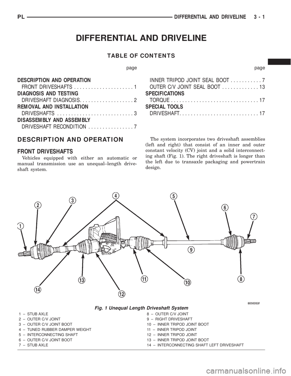
constant velocity (CV) joint and a solid interconnect-
ing shaft (Fig. 1). The right driveshaft is longer than
the left due to transaxle packaging and powertrain
design.
Fig. 1 Unequal Length Driveshaft System
1 ± STUB AXLE
2 ± OUTER C/V JOINT
3 ± OUTER C/V JOINT BOOT
4 ± TUNED RUBBER DAMPER WEIGHT
5 ± INTERCONNECTING SHAFT
6 ± OUTER C/V JOINT BOOT
7 ± STUB AXLE8 ± OUTER C/V JOINT
9 ± RIGHT DRIVESHAFT
10 ± INNER TRIPOD JOINT BOOT
11 ± INNER TRIPOD JOINT
12 ± INNER TRIPOD JOINT
13 ± INNER TRIPOD JOINT BOOT
14 ± INTERCONNECTING SHAFT LEFT DRIVESHAFT
PLDIFFERENTIAL AND DRIVELINE 3 - 1
Page 101 of 1285
BRAKE ROTOR LIMITS
Braking Rotor Rotor ThicknessMinimum
Rotor
ThicknessRotor
Thickness
VariationRotor Run
Out*Rotor Micro
Finish
Front Rotor21.87±22.13 mm
0.861-0.871 in.20.4 mm
0.803 in.0.013 mm
0.0005 in.0.08 mm
0.003 in.15-80 RMS
Rear Rotor8.75±9.25 mm
0.344 -0.364 in.7.25 mm
0.285 in.0.013 mm
0.0005 in.0.08 mm
0.003 in.15-80 RMS
* TIR Total Indicator Reading (Measured On Vehicle)
BRAKE DRUM MACHINING
If a brake drum is deeply scored or warped, it can
be machined on a brake lathe equipped to machine
brake drums. Follow the manufacturers instructions
on the machining procedure.
Measure the brake drum diameter before machin-
ing. If machining the drum will cause the drum to
exceed maximum allowable diameter, do not machine
the brake drum. It needs to be replaced.
CAUTION: Do not machine the brake drum if it will
cause the drum to exceed maximum allowable
diameter.
All brake drums are marked with the maximum
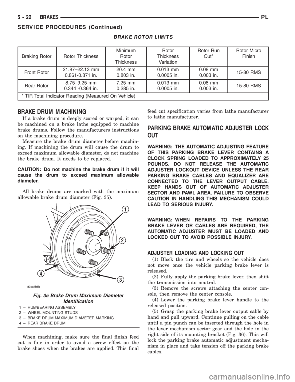
allowable brake drum diameter (Fig. 35).
When machining, make sure the final finish feed
cut is fine in order to avoid a screw effect on the
brake shoes when the brakes are applied. This finalfeed cut specification varies from lathe manufacturer
to lathe manufacturer.
PARKING BRAKE AUTOMATIC ADJUSTER LOCK
OUT
WARNING: THE AUTOMATIC ADJUSTING FEATURE
OF THIS PARKING BRAKE LEVER CONTAINS A
CLOCK SPRING LOADED TO APPROXIMATELY 25
POUNDS. DO NOT RELEASE THE AUTOMATIC
ADJUSTER LOCKOUT DEVICE UNLESS THE REAR
PARKING BRAKE CABLES AND EQUALIZER ARE
CONNECTED TO THE LEVER OUTPUT CABLE.
KEEP HANDS OUT OF AUTOMATIC ADJUSTER
SECTOR AND PAWL AREA. FAILURE TO OBSERVE
CAUTION IN HANDLING THIS MECHANISM COULD
LEAD TO SERIOUS INJURY.
WARNING: WHEN REPAIRS TO THE PARKING
BRAKE LEVER OR CABLES ARE REQUIRED, THE
AUTOMATIC ADJUSTER MUST BE LOADED AND
LOCKED OUT TO AVOID POSSIBLE INJURY.
ADJUSTER LOADING AND LOCKING OUT
(1) Block the tire and wheels so the vehicle does
not move once the vehicle parking brake lever is
released.
(2) Fully apply the parking brake lever, then shift
the transmission into neutral.
(3) Remove the screws attaching the center con-
sole, then remove the center console.
(4) Lower the parking brake lever handle to the
released position.
(5) Grasp the parking brake lever output cable by
hand and pull upward. Continue pulling on the cable
until a pin punch can be inserted through the hole in
the lever mechanism sector gear and the hole in the
right side of its mounting bracket (Fig. 36). This will
lock the parking brake automatic adjustment mecha-
nism in place and take tension off the parking brake
cables.
Fig. 35 Brake Drum Maximum Diameter
Identification
1 ± HUB/BEARING ASSEMBLY
2 ± WHEEL MOUNTING STUDS
3 ± BRAKE DRUM MAXIMUM DIAMETER MARKING
4 ± REAR BRAKE DRUM
5 - 22 BRAKESPL
SERVICE PROCEDURES (Continued)
Page 127 of 1285
PARKING BRAKE LEVER
WARNING: THE AUTOMATIC ADJUSTING FEATURE
OF THIS PARKING BRAKE LEVER CONTAINS A
CLOCK SPRING LOADED TO APPROXIMATELY 25
POUNDS. DO NOT RELEASE THE AUTOMATIC
ADJUSTER LOCKOUT DEVICE UNLESS THE REAR
PARKING BRAKE CABLES AND EQUALIZER ARE
CONNECTED TO THE LEVER OUTPUT CABLE.
KEEP HANDS OUT OF AUTOMATIC ADJUSTER
SECTOR AND PAWL AREA. FAILURE TO OBSERVE
CAUTION IN HANDLING THIS MECHANISM COULD
LEAD TO SERIOUS INJURY.
WARNING: WHEN REPAIRS TO THE PARKING
BRAKE LEVER OR CABLES ARE REQUIRED, THE
AUTOMATIC ADJUSTER MUST BE LOADED AND
LOCKED OUT TO AVOID POSSIBLE INJURY. THE
LEVER ADJUSTMENT MECHANISM CAN BE
LOADED AND LOCKED OUT AS OUTLINED IN THIS
PROCEDURE.
REMOVAL
(1) Block the tire and wheels so the vehicle does
not move once the vehicle parking brake lever is
released.
(2) Fully apply the parking brake lever, then shift
the transmission into neutral.
(3) Remove the screws attaching the center con-
sole, then remove the center console.
(4) Lower the parking brake lever handle to the
released position.
(5) Grasp the parking brake lever output cable by
hand and pull upward. Continue pulling on the cable
until a pin punch can be inserted through the hole in
the lever mechanism sector gear and the hole in the
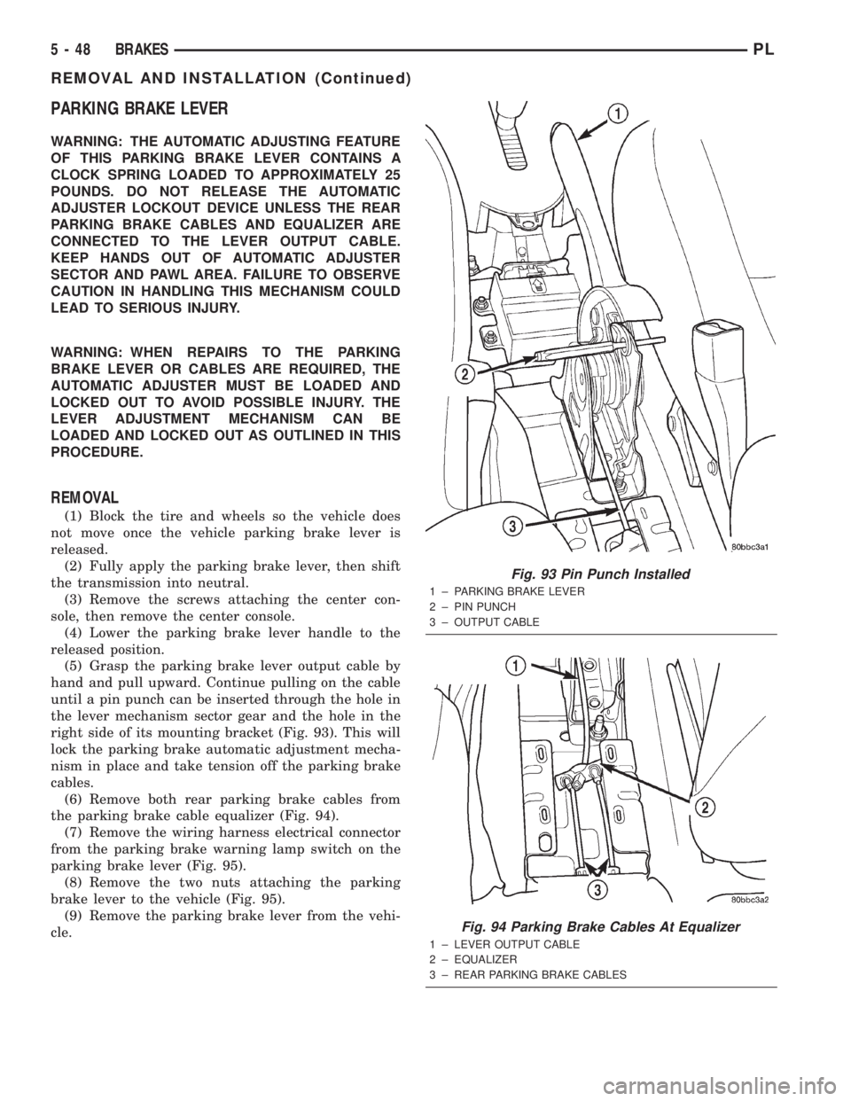
right side of its mounting bracket (Fig. 93). This will
lock the parking brake automatic adjustment mecha-
nism in place and take tension off the parking brake
cables.
(6) Remove both rear parking brake cables from
the parking brake cable equalizer (Fig. 94).
(7) Remove the wiring harness electrical connector
from the parking brake warning lamp switch on the
parking brake lever (Fig. 95).
(8) Remove the two nuts attaching the parking
brake lever to the vehicle (Fig. 95).
(9) Remove the parking brake lever from the vehi-
cle.
Fig. 93 Pin Punch Installed
1 ± PARKING BRAKE LEVER
2 ± PIN PUNCH
3 ± OUTPUT CABLE
Fig. 94 Parking Brake Cables At Equalizer
1 ± LEVER OUTPUT CABLE
2 ± EQUALIZER
3 ± REAR PARKING BRAKE CABLES
5 - 48 BRAKESPL
REMOVAL AND INSTALLATION (Continued)
Page 128 of 1285
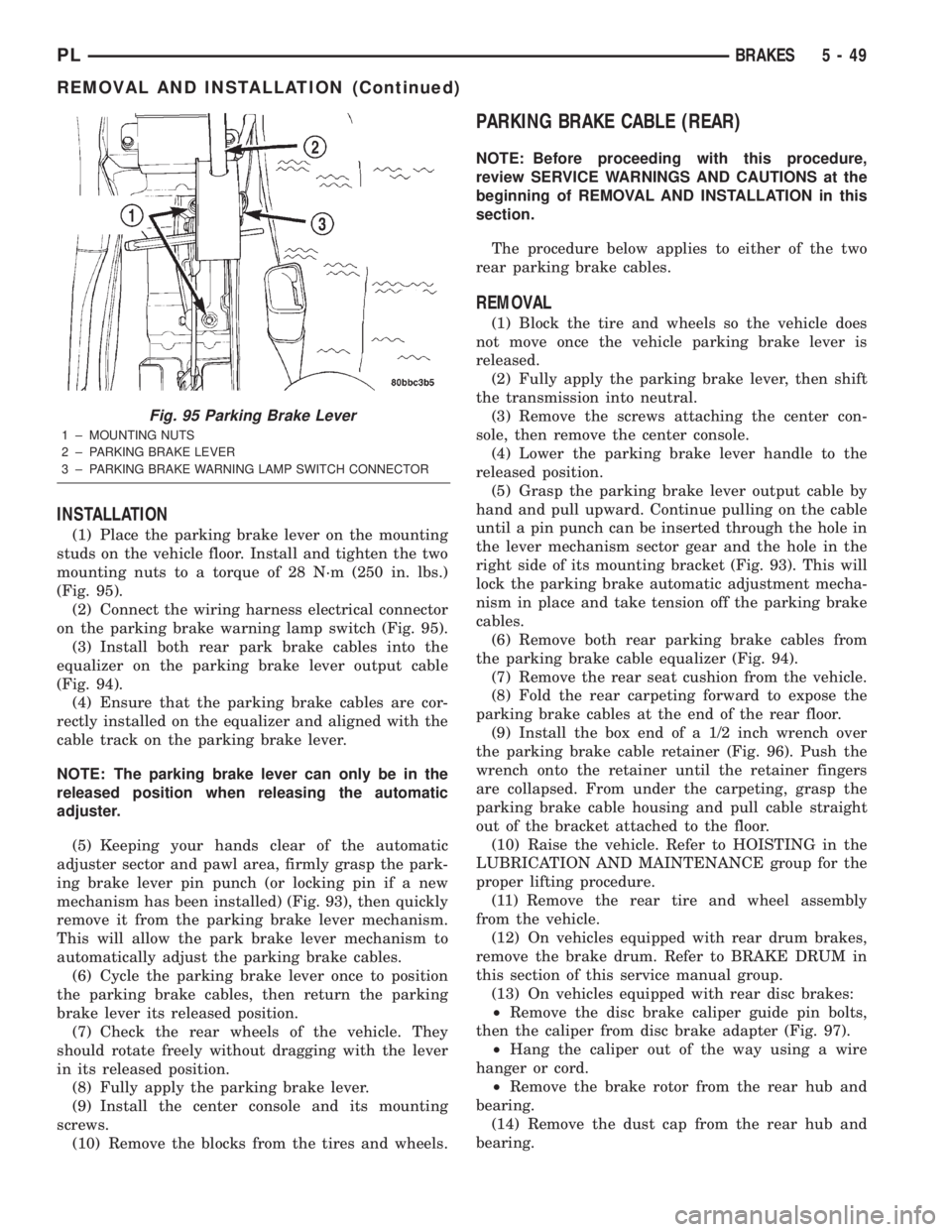
INSTALLATION
(1) Place the parking brake lever on the mounting
studs on the vehicle floor. Install and tighten the two
mounting nuts to a torque of 28 N´m (250 in. lbs.)
(Fig. 95).
(2) Connect the wiring harness electrical connector
on the parking brake warning lamp switch (Fig. 95).
(3) Install both rear park brake cables into the
equalizer on the parking brake lever output cable
(Fig. 94).
(4) Ensure that the parking brake cables are cor-
rectly installed on the equalizer and aligned with the
cable track on the parking brake lever.
NOTE: The parking brake lever can only be in the
released position when releasing the automatic
adjuster.
(5) Keeping your hands clear of the automatic
adjuster sector and pawl area, firmly grasp the park-
ing brake lever pin punch (or locking pin if a new
mechanism has been installed) (Fig. 93), then quickly
remove it from the parking brake lever mechanism.
This will allow the park brake lever mechanism to
automatically adjust the parking brake cables.
(6) Cycle the parking brake lever once to position
the parking brake cables, then return the parking
brake lever its released position.
(7) Check the rear wheels of the vehicle. They
should rotate freely without dragging with the lever
in its released position.
(8) Fully apply the parking brake lever.
(9) Install the center console and its mounting
screws.
(10) Remove the blocks from the tires and wheels.
PARKING BRAKE CABLE (REAR)
NOTE: Before proceeding with this procedure,
review SERVICE WARNINGS AND CAUTIONS at the
beginning of REMOVAL AND INSTALLATION in this
section.
The procedure below applies to either of the two
rear parking brake cables.
REMOVAL
(1) Block the tire and wheels so the vehicle does
not move once the vehicle parking brake lever is
released.
(2) Fully apply the parking brake lever, then shift
the transmission into neutral.
(3) Remove the screws attaching the center con-
sole, then remove the center console.
(4) Lower the parking brake lever handle to the
released position.
(5) Grasp the parking brake lever output cable by
hand and pull upward. Continue pulling on the cable
until a pin punch can be inserted through the hole in
the lever mechanism sector gear and the hole in the
right side of its mounting bracket (Fig. 93). This will
lock the parking brake automatic adjustment mecha-
nism in place and take tension off the parking brake
cables.
(6) Remove both rear parking brake cables from
the parking brake cable equalizer (Fig. 94).
(7) Remove the rear seat cushion from the vehicle.
(8) Fold the rear carpeting forward to expose the
parking brake cables at the end of the rear floor.
(9) Install the box end of a 1/2 inch wrench over
the parking brake cable retainer (Fig. 96). Push the
wrench onto the retainer until the retainer fingers
are collapsed. From under the carpeting, grasp the
parking brake cable housing and pull cable straight
out of the bracket attached to the floor.
(10) Raise the vehicle. Refer to HOISTING in the
LUBRICATION AND MAINTENANCE group for the
proper lifting procedure.
(11) Remove the rear tire and wheel assembly
from the vehicle.
(12) On vehicles equipped with rear drum brakes,
remove the brake drum. Refer to BRAKE DRUM in
this section of this service manual group.
(13) On vehicles equipped with rear disc brakes:
²Remove the disc brake caliper guide pin bolts,
then the caliper from disc brake adapter (Fig. 97).
²Hang the caliper out of the way using a wire
hanger or cord.
²Remove the brake rotor from the rear hub and
bearing.
(14) Remove the dust cap from the rear hub and
bearing.
Fig. 95 Parking Brake Lever
1 ± MOUNTING NUTS
2 ± PARKING BRAKE LEVER
3 ± PARKING BRAKE WARNING LAMP SWITCH CONNECTOR
PLBRAKES 5 - 49
REMOVAL AND INSTALLATION (Continued)
Page 180 of 1285
COOLING SYSTEM
TABLE OF CONTENTS
page page
DESCRIPTION AND OPERATION
COOLING SYSTEM........................1
COOLANT...............................2
COOLANT PERFORMANCE..................2
COOLANT RECOVERY SYSTEM..............3
ENGINE THERMOSTAT.....................3
RADIATOR..............................3
RADIATOR COOLING FAN MODULE...........3
COOLING SYSTEM PRESSURE CAP..........4
RADIATOR HOSES AND CLAMPS............5
WATER PUMP...........................5
AUTOMATIC TRANSMISSION OIL COOLER.....6
ACCESSORY DRIVE BELTS.................6
ENGINE BLOCK HEATER...................6
DIAGNOSIS AND TESTING
COOLING SYSTEM DIAGNOSIS..............7
ENGINE THERMOSTAT TESTING............14
ACCESSORY DRIVE BELT DIAGNOSIS........14
WATER PUMP DIAGNOSIS................15
COOLING SYSTEM FLOW CHECK...........15
ELECTRIC FAN MOTOR TEST...............15
COOLANT CONCENTRATION TESTING........15
TESTING COOLING SYSTEM FOR LEAKS.....15
PRESSURE CAP TO FILLER NECK SEAL
PRESSURE RELIEF CHECK...............16
PRESSURE TESTING COOLING SYSTEM
PRESSURE CAP.......................16
LOW COOLANT LEVEL AERATION...........17
DEAERATION...........................17
TEMPERATURE GAUGE INDICATION.........17
ENGINE BLOCK HEATER..................17
SERVICE PROCEDURES
COOLANT LEVEL CHECKÐROUTINE.........17COOLANTÐADDING ADDITIONAL...........18
COOLANT LEVELÐSERVICING.............18
COOLING SYSTEMÐDRAINING.............19
COOLING SYSTEMÐREFILLING............19
REMOVAL AND INSTALLATION
WATER PUMP..........................19
WATER PUMP INLET TUBE................20
ENGINE THERMOSTAT....................20
RADIATOR.............................21
RADIATOR DRAINCOCK...................22
COOLING FAN MODULE...................22
COOLANT RECOVERY CONTAINER..........23
ENGINE BLOCK HEATER..................24
ACCESSORY DRIVE BELTS................24
AUTOMATIC BELT TENSIONER & PULLEY....26
DISASSEMBLY AND ASSEMBLY
COOLING FAN MODULE...................26
CLEANING AND INSPECTION
WATER PUMP..........................28
ACCESSORY DRIVE BELT INSPECTION.......28
COOLING SYSTEM CAP...................28
COOLING SYSTEM CLEANING..............28
RADIATOR FLUSHING....................28
REVERSE FLUSHING.....................29
CHEMICAL CLEANING....................29
ADJUSTMENTS
BELT TENSION..........................29
SPECIFICATIONS
COOLING SYSTEM CAPACITY..............30
TORQUE SPECIFICATIONS.................30
SPECIAL TOOLS
COOLING..............................30
DESCRIPTION AND OPERATION
COOLING SYSTEM
The cooling system consists of an engine cooling
module, thermostat, coolant, and a water pump to
circulate the coolant. The engine cooling module may
consist of a radiator, electric fan motor, fan, shroud,
coolant reserve system, transmission oil cooler, hoses,clamps, air conditioning condenser and transmission
oil lines.
²When the Engine is cold: The thermostat is
closed and the cooling system has no flow through
the radiator. The coolant flows through the engine,
heater system and bypass.
²When the Engine is warm: Thermostat is open
and the cooling system has flow through the radiator,
engine, heater system, and bypass.
PLCOOLING SYSTEM 7 - 1
Page 182 of 1285
protection. MopartAntifreeze or the equivalent is
recommended for best engine cooling without corro-
sion. When mixed only to a freeze point of -37ÉC
(-35ÉF) to -59ÉC (-50ÉF). If it looses color or becomes
contaminated, drain, flush, and replace with fresh
properly mixed solution.
COOLANT RECOVERY SYSTEM
This system works in conjunction with the radiator
pressure cap to utilize thermal expansion and con-
traction of the coolant to keep the coolant free of
trapped air. The system provides space for expansion
and contraction. Also, the system provides a conve-
nient and safe method for checking and adjusting the
coolant level at atmospheric pressure without remov-
ing the pressure cap. It also provides some reserve
coolant to compensate for minor leaks and evapora-
tion or boiling losses. All vehicles are equipped with
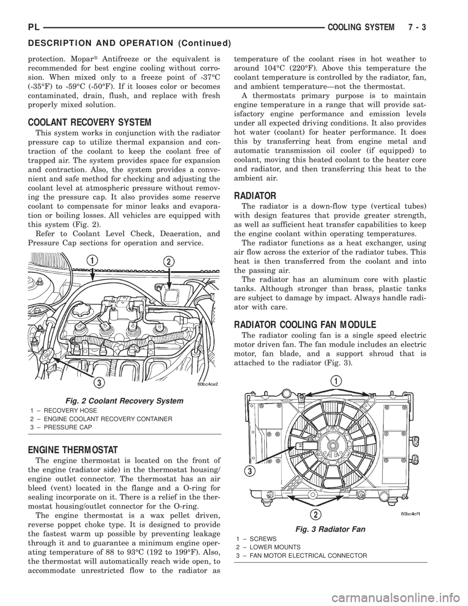
this system (Fig. 2).
Refer to Coolant Level Check, Deaeration, and
Pressure Cap sections for operation and service.
ENGINE THERMOSTAT
The engine thermostat is located on the front of
the engine (radiator side) in the thermostat housing/
engine outlet connector. The thermostat has an air
bleed (vent) located in the flange and a O-ring for
sealing incorporate on it. There is a relief in the ther-
mostat housing/outlet connector for the O-ring.
The engine thermostat is a wax pellet driven,
reverse poppet choke type. It is designed to provide
the fastest warm up possible by preventing leakage
through it and to guarantee a minimum engine oper-
ating temperature of 88 to 93ÉC (192 to 199ÉF). Also,
the thermostat will automatically reach wide open, to
accommodate unrestricted flow to the radiator astemperature of the coolant rises in hot weather to
around 104ÉC (220ÉF). Above this temperature the
coolant temperature is controlled by the radiator, fan,
and ambient temperatureÐnot the thermostat.
A thermostats primary purpose is to maintain
engine temperature in a range that will provide sat-
isfactory engine performance and emission levels
under all expected driving conditions. It also provides
hot water (coolant) for heater performance. It does
this by transferring heat from engine metal and
automatic transmission oil cooler (if equipped) to
coolant, moving this heated coolant to the heater core
and radiator, and then transferring this heat to the
ambient air.
RADIATOR
The radiator is a down-flow type (vertical tubes)
with design features that provide greater strength,
as well as sufficient heat transfer capabilities to keep
the engine coolant within operating temperatures.
The radiator functions as a heat exchanger, using
air flow across the exterior of the radiator tubes. This
heat is then transferred from the coolant and into
the passing air.
The radiator has an aluminum core with plastic
tanks. Although stronger than brass, plastic tanks
are subject to damage by impact. Always handle radi-
ator with care.
RADIATOR COOLING FAN MODULE
The radiator cooling fan is a single speed electric
motor driven fan. The fan module includes an electric
motor, fan blade, and a support shroud that is
attached to the radiator (Fig. 3).
Fig. 2 Coolant Recovery System
1 ± RECOVERY HOSE
2 ± ENGINE COOLANT RECOVERY CONTAINER
3 ± PRESSURE CAP
Fig. 3 Radiator Fan
1 ± SCREWS
2 ± LOWER MOUNTS
3 ± FAN MOTOR ELECTRICAL CONNECTOR
PLCOOLING SYSTEM 7 - 3
DESCRIPTION AND OPERATION (Continued)
Page 185 of 1285
AUTOMATIC TRANSMISSION OIL COOLER
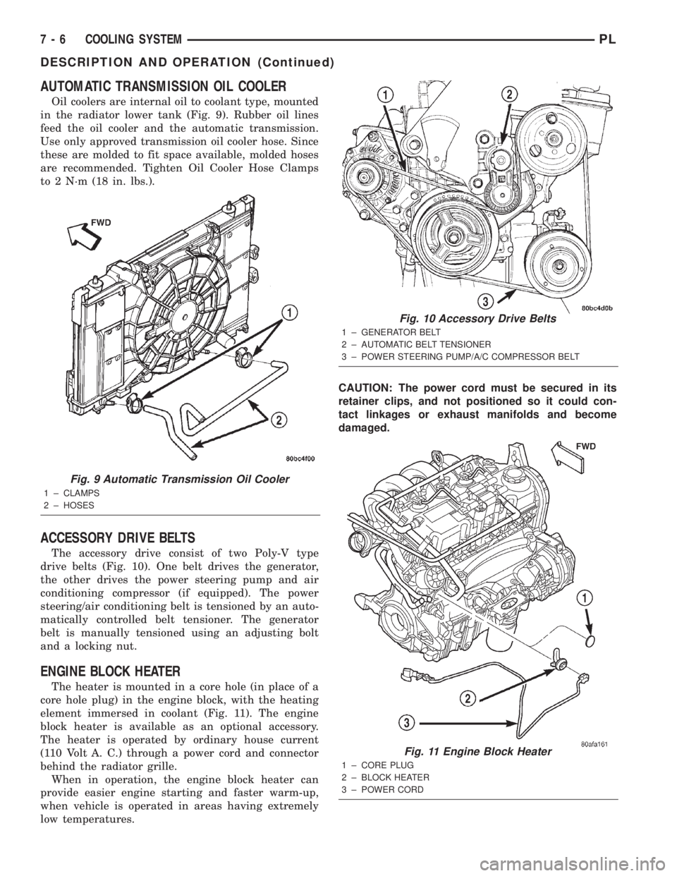
Oil coolers are internal oil to coolant type, mounted
in the radiator lower tank (Fig. 9). Rubber oil lines
feed the oil cooler and the automatic transmission.
Use only approved transmission oil cooler hose. Since
these are molded to fit space available, molded hoses
are recommended. Tighten Oil Cooler Hose Clamps
to 2 N´m (18 in. lbs.).
ACCESSORY DRIVE BELTS
The accessory drive consist of two Poly-V type
drive belts (Fig. 10). One belt drives the generator,
the other drives the power steering pump and air
conditioning compressor (if equipped). The power
steering/air conditioning belt is tensioned by an auto-
matically controlled belt tensioner. The generator
belt is manually tensioned using an adjusting bolt
and a locking nut.
ENGINE BLOCK HEATER
The heater is mounted in a core hole (in place of a
core hole plug) in the engine block, with the heating
element immersed in coolant (Fig. 11). The engine
block heater is available as an optional accessory.
The heater is operated by ordinary house current
(110 Volt A. C.) through a power cord and connector
behind the radiator grille.
When in operation, the engine block heater can
provide easier engine starting and faster warm-up,
when vehicle is operated in areas having extremely
low temperatures.CAUTION: The power cord must be secured in its
retainer clips, and not positioned so it could con-
tact linkages or exhaust manifolds and become
damaged.
Fig. 9 Automatic Transmission Oil Cooler
1 ± CLAMPS
2 ± HOSES
Fig. 10 Accessory Drive Belts
1 ± GENERATOR BELT
2 ± AUTOMATIC BELT TENSIONER
3 ± POWER STEERING PUMP/A/C COMPRESSOR BELT
Fig. 11 Engine Block Heater
1 ± CORE PLUG
2 ± BLOCK HEATER
3 ± POWER CORD
7 - 6 COOLING SYSTEMPL
DESCRIPTION AND OPERATION (Continued)
Page 200 of 1285
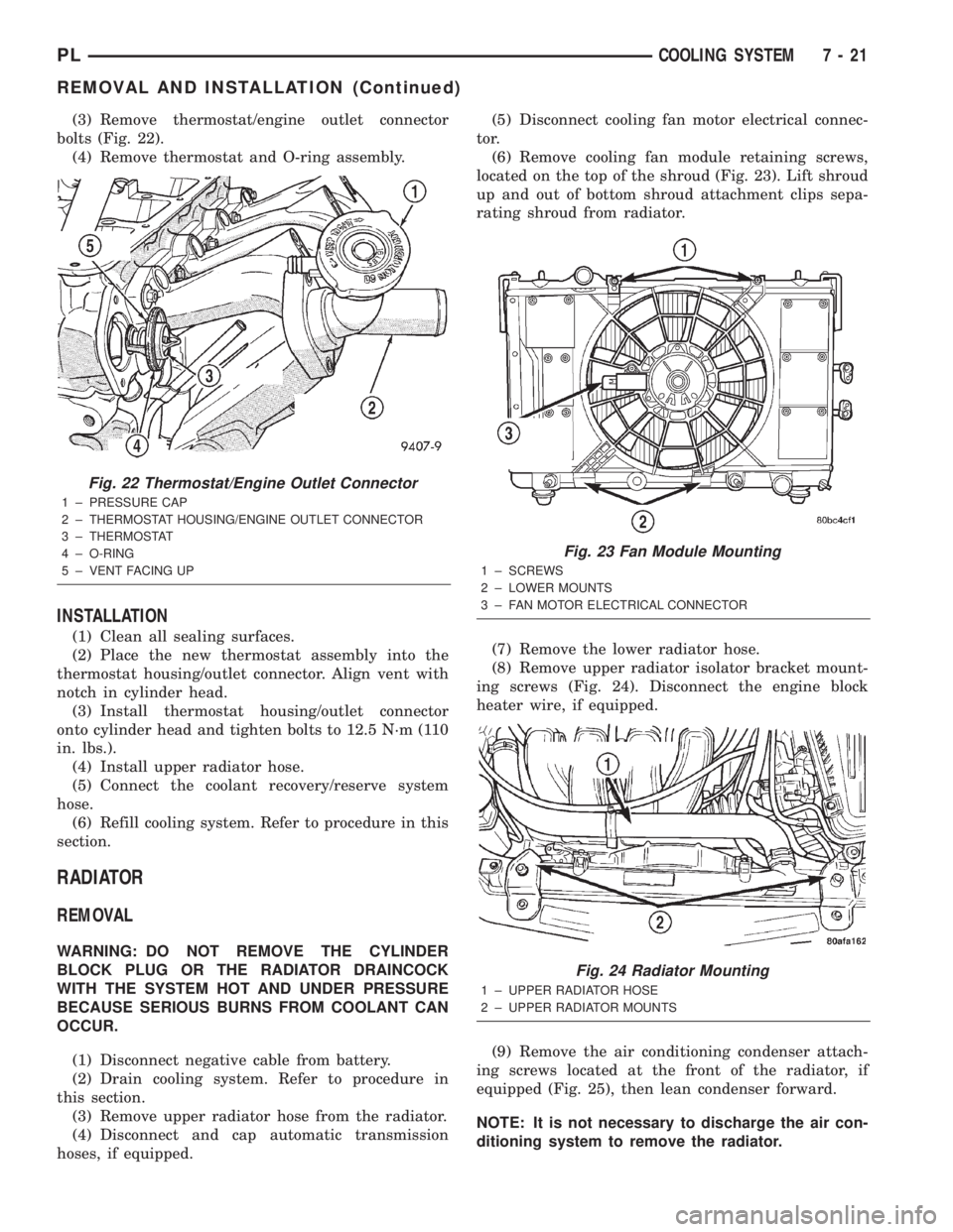
(3) Remove thermostat/engine outlet connector
bolts (Fig. 22).
(4) Remove thermostat and O-ring assembly.
INSTALLATION
(1) Clean all sealing surfaces.
(2) Place the new thermostat assembly into the
thermostat housing/outlet connector. Align vent with
notch in cylinder head.
(3) Install thermostat housing/outlet connector
onto cylinder head and tighten bolts to 12.5 N´m (110
in. lbs.).
(4) Install upper radiator hose.
(5) Connect the coolant recovery/reserve system
hose.
(6) Refill cooling system. Refer to procedure in this
section.
RADIATOR
REMOVAL
WARNING: DO NOT REMOVE THE CYLINDER
BLOCK PLUG OR THE RADIATOR DRAINCOCK
WITH THE SYSTEM HOT AND UNDER PRESSURE
BECAUSE SERIOUS BURNS FROM COOLANT CAN
OCCUR.
(1) Disconnect negative cable from battery.
(2) Drain cooling system. Refer to procedure in
this section.
(3) Remove upper radiator hose from the radiator.
(4) Disconnect and cap automatic transmission
hoses, if equipped.(5) Disconnect cooling fan motor electrical connec-
tor.
(6) Remove cooling fan module retaining screws,
located on the top of the shroud (Fig. 23). Lift shroud
up and out of bottom shroud attachment clips sepa-
rating shroud from radiator.
(7) Remove the lower radiator hose.
(8) Remove upper radiator isolator bracket mount-
ing screws (Fig. 24). Disconnect the engine block
heater wire, if equipped.
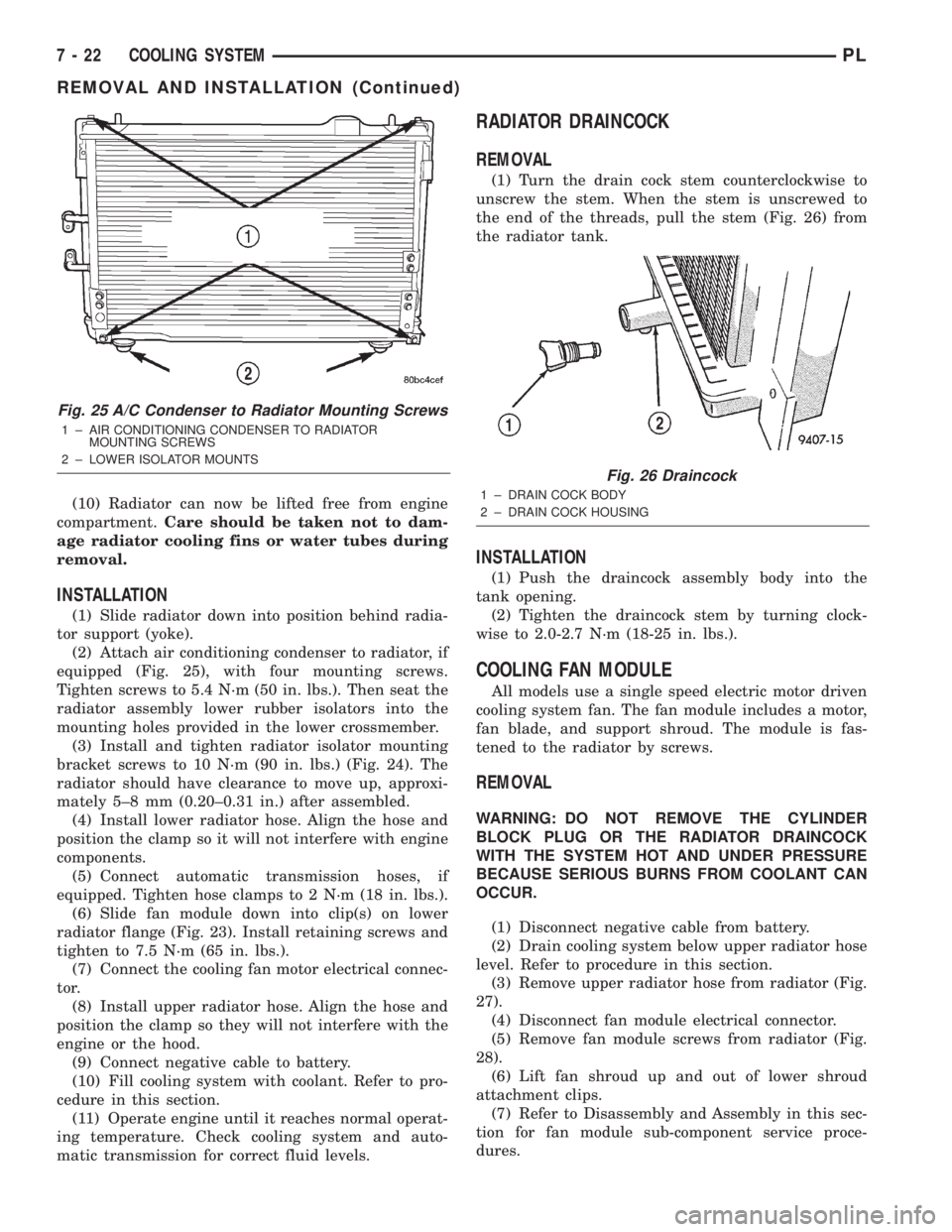
(9) Remove the air conditioning condenser attach-
ing screws located at the front of the radiator, if
equipped (Fig. 25), then lean condenser forward.
NOTE: It is not necessary to discharge the air con-
ditioning system to remove the radiator.
Fig. 22 Thermostat/Engine Outlet Connector
1 ± PRESSURE CAP
2 ± THERMOSTAT HOUSING/ENGINE OUTLET CONNECTOR
3 ± THERMOSTAT
4 ± O-RING
5 ± VENT FACING UP
Fig. 23 Fan Module Mounting
1 ± SCREWS
2 ± LOWER MOUNTS
3 ± FAN MOTOR ELECTRICAL CONNECTOR
Fig. 24 Radiator Mounting
1 ± UPPER RADIATOR HOSE
2 ± UPPER RADIATOR MOUNTS
PLCOOLING SYSTEM 7 - 21
REMOVAL AND INSTALLATION (Continued)
Page 201 of 1285
(10) Radiator can now be lifted free from engine
compartment.Care should be taken not to dam-
age radiator cooling fins or water tubes during
removal.
INSTALLATION
(1) Slide radiator down into position behind radia-
tor support (yoke).
(2) Attach air conditioning condenser to radiator, if
equipped (Fig. 25), with four mounting screws.
Tighten screws to 5.4 N´m (50 in. lbs.). Then seat the
radiator assembly lower rubber isolators into the
mounting holes provided in the lower crossmember.
(3) Install and tighten radiator isolator mounting
bracket screws to 10 N´m (90 in. lbs.) (Fig. 24). The
radiator should have clearance to move up, approxi-
mately 5±8 mm (0.20±0.31 in.) after assembled.
(4) Install lower radiator hose. Align the hose and
position the clamp so it will not interfere with engine
components.
(5) Connect automatic transmission hoses, if
equipped. Tighten hose clamps to 2 N´m (18 in. lbs.).
(6) Slide fan module down into clip(s) on lower
radiator flange (Fig. 23). Install retaining screws and
tighten to 7.5 N´m (65 in. lbs.).
(7) Connect the cooling fan motor electrical connec-
tor.
(8) Install upper radiator hose. Align the hose and
position the clamp so they will not interfere with the
engine or the hood.
(9) Connect negative cable to battery.
(10) Fill cooling system with coolant. Refer to pro-
cedure in this section.
(11) Operate engine until it reaches normal operat-
ing temperature. Check cooling system and auto-
matic transmission for correct fluid levels.
RADIATOR DRAINCOCK
REMOVAL
(1) Turn the drain cock stem counterclockwise to
unscrew the stem. When the stem is unscrewed to
the end of the threads, pull the stem (Fig. 26) from
the radiator tank.
INSTALLATION
(1) Push the draincock assembly body into the
tank opening.
(2) Tighten the draincock stem by turning clock-
wise to 2.0-2.7 N´m (18-25 in. lbs.).
COOLING FAN MODULE
All models use a single speed electric motor driven
cooling system fan. The fan module includes a motor,
fan blade, and support shroud. The module is fas-
tened to the radiator by screws.
REMOVAL
WARNING: DO NOT REMOVE THE CYLINDER
BLOCK PLUG OR THE RADIATOR DRAINCOCK
WITH THE SYSTEM HOT AND UNDER PRESSURE
BECAUSE SERIOUS BURNS FROM COOLANT CAN
OCCUR.
(1) Disconnect negative cable from battery.
(2) Drain cooling system below upper radiator hose
level. Refer to procedure in this section.
(3) Remove upper radiator hose from radiator (Fig.
27).
(4) Disconnect fan module electrical connector.
(5) Remove fan module screws from radiator (Fig.
28).
(6) Lift fan shroud up and out of lower shroud
attachment clips.
(7) Refer to Disassembly and Assembly in this sec-
tion for fan module sub-component service proce-
dures.
Fig. 25 A/C Condenser to Radiator Mounting Screws
1 ± AIR CONDITIONING CONDENSER TO RADIATOR
MOUNTING SCREWS
2 ± LOWER ISOLATOR MOUNTS
Fig. 26 Draincock
1 ± DRAIN COCK BODY
2 ± DRAIN COCK HOUSING
7 - 22 COOLING SYSTEMPL
REMOVAL AND INSTALLATION (Continued)