open hood DODGE NEON 2000 Service Repair Manual
[x] Cancel search | Manufacturer: DODGE, Model Year: 2000, Model line: NEON, Model: DODGE NEON 2000Pages: 1285, PDF Size: 29.42 MB
Page 8 of 1285
JUMP STARTING, TOWING, AND HOISTING
TABLE OF CONTENTS
page page
DESCRIPTION AND OPERATION
JUMP STARTING PROCEDURE...............7
TOWING RECOMMENDATIONS...............7
HOISTING RECOMMENDATIONS.............7SERVICE PROCEDURES
JUMP STARTING PROCEDURE...............7
TOWING RECOMMENDATIONS...............8
HOISTING RECOMMENDATIONS.............9
DESCRIPTION AND OPERATION
JUMP STARTING PROCEDURE
Describes the procedure for starting a disable vehi-
cle.
TOWING RECOMMENDATIONS
Describes the recommended towing procedures.
HOISTING RECOMMENDATIONS
Describes the location of hoisting and jacking
points so that the vehicle can be lifted by a floor jack
or hoist.
SERVICE PROCEDURES
JUMP STARTING PROCEDURE
WARNING: REVIEW ALL SAFETY PRECAUTIONS
AND WARNINGS IN GROUP 8A, BATTERY/START-
ING/CHARGING SYSTEMS DIAGNOSTICS. DO NOT
JUMP START A FROZEN BATTERY, PERSONAL
INJURY CAN RESULT. DO NOT JUMP START WHEN
MAINTENANCE FREE BATTERY INDICATOR DOT IS
YELLOW OR BRIGHT COLOR. DO NOT JUMP
START A VEHICLE WHEN THE BATTERY FLUID IS
BELOW THE TOP OF LEAD PLATES. DO NOT
ALLOW JUMPER CABLE CLAMPS TO TOUCH
EACH OTHER WHEN CONNECTED TO A BOOSTER
SOURCE. DO NOT USE OPEN FLAME NEAR BAT-
TERY. REMOVE METALLIC JEWELRY WORN ON
HANDS OR WRISTS TO AVOID INJURY BY ACCI-
DENTAL ARCING OF BATTERY CURRENT. WHEN
USING A HIGH OUTPUT BOOSTING DEVICE, DO
NOT ALLOW BATTERY VOLTAGE TO EXCEED 16
VOLTS. REFER TO INSTRUCTIONS PROVIDED
WITH DEVICE BEING USED.
CAUTION: When using another vehicle as a
booster, do not allow vehicles to touch. Electrical
systems can be damaged on either vehicle.
TO JUMP START A DISABLED VEHICLE:
(1) Raise hood on disabled vehicle and visually
inspect engine compartment for:
²Battery cable clamp condition, clean if necessary.
²Frozen battery.
²Yellow or bright color test indicator, if equipped.
²Low battery fluid level.
²Generator drive belt condition and tension.
²Fuel fumes or leakage, correct if necessary.
CAUTION: If the cause of starting problem on dis-
abled vehicle is severe, damage to booster vehicle
charging system can result.
(2) When using another vehicle as a booster
source, park the booster vehicle within cable reach.
Turn off all accessories, set the parking brake, place
the automatic transmission in PARK or the manual
transmission in NEUTRAL and turn the ignition
OFF.
(3) On disabled vehicle, place gear selector in park
or neutral and set park brake. Turn off all accesso-
ries.
(4) Connect jumper cables to booster battery. RED
clamp to positive terminal (+). BLACK clamp to neg-
ative terminal (-). DO NOT allow clamps at opposite
end of cables to touch, electrical arc will result.
Review all warnings in this procedure.
(5) On disabled vehicle, connect RED jumper cable
clamp to positive (+) terminal. Connect BLACK
jumper cable clamp to engine ground as close to the
ground cable attaching point as possible (Fig. 1).
(6) Start the engine in the vehicle which has the
booster battery, let the engine idle a few minutes,
then start the engine in the vehicle with the dis-
charged battery.
CAUTION: Do not crank starter motor on disabled
vehicle for more than 15 seconds, starter will over-
heat and could fail.
(7) Allow battery in disabled vehicle to charge to
at least 12.4 volts (75% charge) before attempting to
start engine. If engine does not start within 15 sec-
PLLUBRICATION AND MAINTENANCE 0 - 7
Page 26 of 1285
(6) Remove the two bolts attaching the strut to the
steering knuckle (Fig. 1).
(7) Lower the vehicle just enough to open the
hood, but without letting the tires touch the floor.
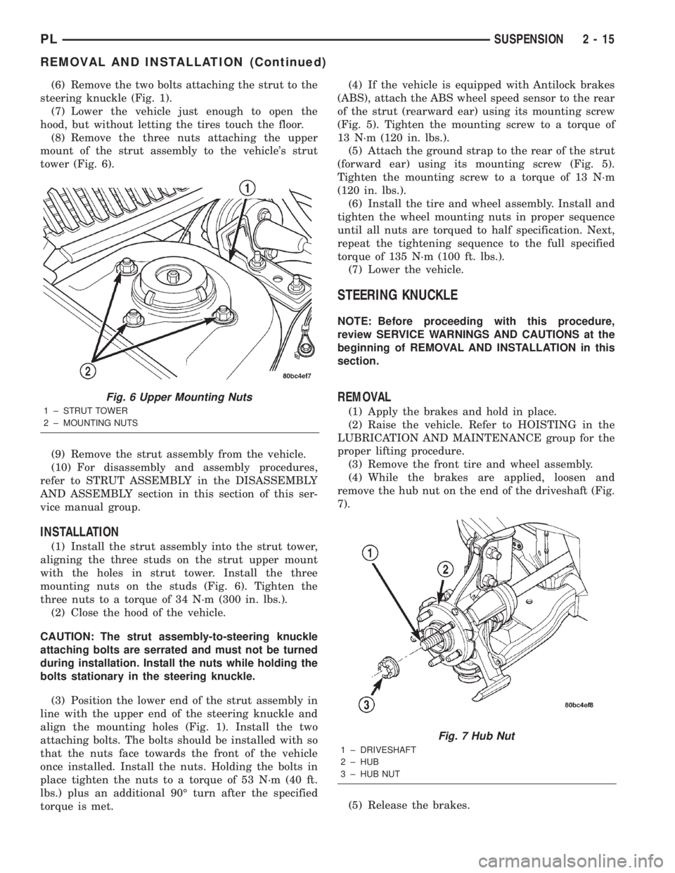
(8) Remove the three nuts attaching the upper
mount of the strut assembly to the vehicle's strut
tower (Fig. 6).
(9) Remove the strut assembly from the vehicle.
(10) For disassembly and assembly procedures,
refer to STRUT ASSEMBLY in the DISASSEMBLY
AND ASSEMBLY section in this section of this ser-
vice manual group.
INSTALLATION
(1) Install the strut assembly into the strut tower,
aligning the three studs on the strut upper mount
with the holes in strut tower. Install the three
mounting nuts on the studs (Fig. 6). Tighten the
three nuts to a torque of 34 N´m (300 in. lbs.).
(2) Close the hood of the vehicle.
CAUTION: The strut assembly-to-steering knuckle
attaching bolts are serrated and must not be turned
during installation. Install the nuts while holding the
bolts stationary in the steering knuckle.
(3) Position the lower end of the strut assembly in
line with the upper end of the steering knuckle and
align the mounting holes (Fig. 1). Install the two
attaching bolts. The bolts should be installed with so
that the nuts face towards the front of the vehicle
once installed. Install the nuts. Holding the bolts in
place tighten the nuts to a torque of 53 N´m (40 ft.
lbs.) plus an additional 90É turn after the specified
torque is met.(4) If the vehicle is equipped with Antilock brakes
(ABS), attach the ABS wheel speed sensor to the rear
of the strut (rearward ear) using its mounting screw
(Fig. 5). Tighten the mounting screw to a torque of
13 N´m (120 in. lbs.).
(5) Attach the ground strap to the rear of the strut
(forward ear) using its mounting screw (Fig. 5).
Tighten the mounting screw to a torque of 13 N´m
(120 in. lbs.).
(6) Install the tire and wheel assembly. Install and
tighten the wheel mounting nuts in proper sequence
until all nuts are torqued to half specification. Next,
repeat the tightening sequence to the full specified
torque of 135 N´m (100 ft. lbs.).
(7) Lower the vehicle.
STEERING KNUCKLE
NOTE: Before proceeding with this procedure,
review SERVICE WARNINGS AND CAUTIONS at the
beginning of REMOVAL AND INSTALLATION in this
section.
REMOVAL
(1) Apply the brakes and hold in place.
(2) Raise the vehicle. Refer to HOISTING in the
LUBRICATION AND MAINTENANCE group for the
proper lifting procedure.
(3) Remove the front tire and wheel assembly.
(4) While the brakes are applied, loosen and
remove the hub nut on the end of the driveshaft (Fig.
7).
(5) Release the brakes.
Fig. 6 Upper Mounting Nuts
1 ± STRUT TOWER
2 ± MOUNTING NUTS
Fig. 7 Hub Nut
1 ± DRIVESHAFT
2 ± HUB
3 ± HUB NUT
PLSUSPENSION 2 - 15
REMOVAL AND INSTALLATION (Continued)
Page 201 of 1285
(10) Radiator can now be lifted free from engine
compartment.Care should be taken not to dam-
age radiator cooling fins or water tubes during
removal.
INSTALLATION
(1) Slide radiator down into position behind radia-
tor support (yoke).
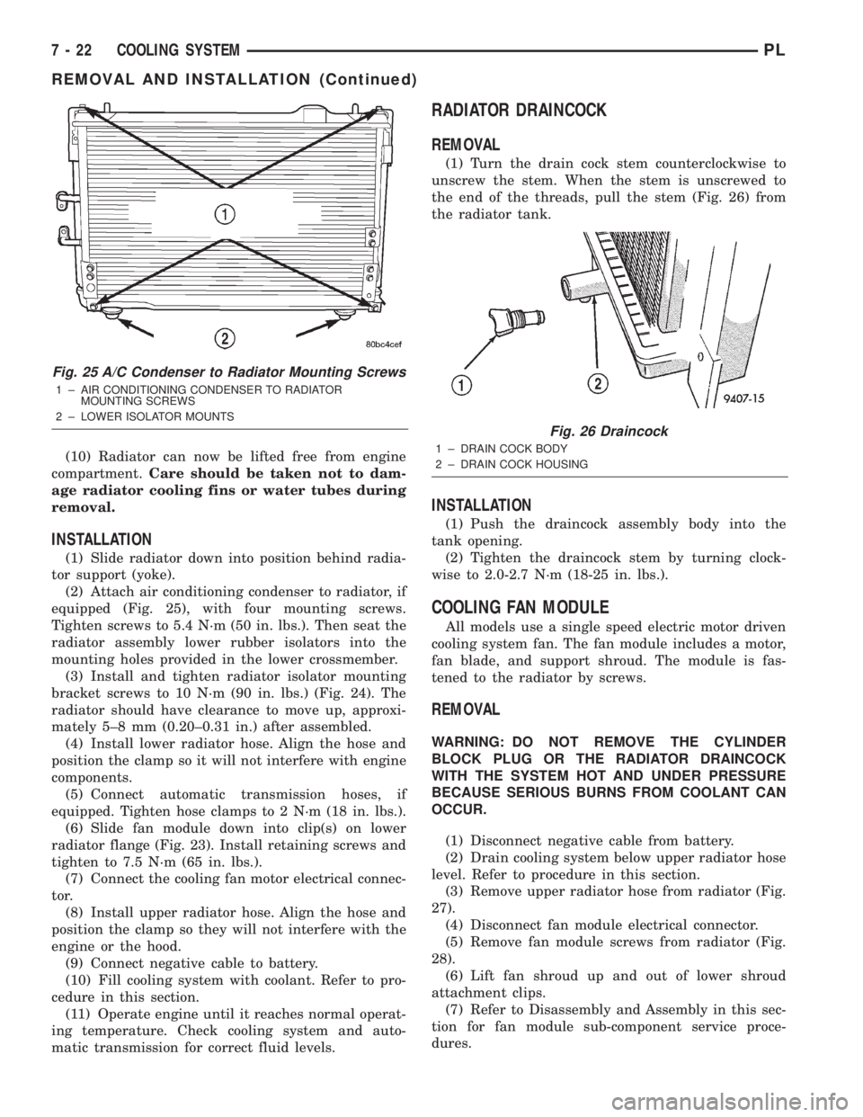
(2) Attach air conditioning condenser to radiator, if
equipped (Fig. 25), with four mounting screws.
Tighten screws to 5.4 N´m (50 in. lbs.). Then seat the
radiator assembly lower rubber isolators into the
mounting holes provided in the lower crossmember.
(3) Install and tighten radiator isolator mounting
bracket screws to 10 N´m (90 in. lbs.) (Fig. 24). The
radiator should have clearance to move up, approxi-
mately 5±8 mm (0.20±0.31 in.) after assembled.
(4) Install lower radiator hose. Align the hose and
position the clamp so it will not interfere with engine
components.
(5) Connect automatic transmission hoses, if
equipped. Tighten hose clamps to 2 N´m (18 in. lbs.).
(6) Slide fan module down into clip(s) on lower
radiator flange (Fig. 23). Install retaining screws and
tighten to 7.5 N´m (65 in. lbs.).
(7) Connect the cooling fan motor electrical connec-
tor.
(8) Install upper radiator hose. Align the hose and
position the clamp so they will not interfere with the
engine or the hood.
(9) Connect negative cable to battery.
(10) Fill cooling system with coolant. Refer to pro-
cedure in this section.
(11) Operate engine until it reaches normal operat-
ing temperature. Check cooling system and auto-
matic transmission for correct fluid levels.
RADIATOR DRAINCOCK
REMOVAL
(1) Turn the drain cock stem counterclockwise to
unscrew the stem. When the stem is unscrewed to
the end of the threads, pull the stem (Fig. 26) from
the radiator tank.
INSTALLATION
(1) Push the draincock assembly body into the
tank opening.
(2) Tighten the draincock stem by turning clock-
wise to 2.0-2.7 N´m (18-25 in. lbs.).
COOLING FAN MODULE
All models use a single speed electric motor driven
cooling system fan. The fan module includes a motor,
fan blade, and support shroud. The module is fas-
tened to the radiator by screws.
REMOVAL
WARNING: DO NOT REMOVE THE CYLINDER
BLOCK PLUG OR THE RADIATOR DRAINCOCK
WITH THE SYSTEM HOT AND UNDER PRESSURE
BECAUSE SERIOUS BURNS FROM COOLANT CAN
OCCUR.
(1) Disconnect negative cable from battery.
(2) Drain cooling system below upper radiator hose
level. Refer to procedure in this section.
(3) Remove upper radiator hose from radiator (Fig.
27).
(4) Disconnect fan module electrical connector.
(5) Remove fan module screws from radiator (Fig.
28).
(6) Lift fan shroud up and out of lower shroud
attachment clips.
(7) Refer to Disassembly and Assembly in this sec-
tion for fan module sub-component service proce-
dures.
Fig. 25 A/C Condenser to Radiator Mounting Screws
1 ± AIR CONDITIONING CONDENSER TO RADIATOR
MOUNTING SCREWS
2 ± LOWER ISOLATOR MOUNTS
Fig. 26 Draincock
1 ± DRAIN COCK BODY
2 ± DRAIN COCK HOUSING
7 - 22 COOLING SYSTEMPL
REMOVAL AND INSTALLATION (Continued)
Page 210 of 1285
BATTERY
TABLE OF CONTENTS
page page
GENERAL INFORMATION
INTRODUCTION..........................1
DESCRIPTION AND OPERATION
BATTERY IGNITION OFF DRAW (IOD).........2
CHARGING TIME REQUIRED................2
DIAGNOSIS AND TESTING
BATTERY BUILT-IN TEST INDICATOR.........3
BATTERY IGNITION OFF DRAW (IOD).........4
BATTERY LOAD TEST......................6
BATTERY OPEN CIRCUIT VOLTAGE...........7
SERVICE PROCEDURES
BATTERY CHARGING......................7CHARGING COMPLETELY DISCHARGED
BATTERY..............................8
VISUAL INSPECTION......................9
REMOVAL AND INSTALLATION
BATTERY...............................10
BATTERY THERMOWRAP..................10
BATTERY TRAY..........................11
SPECIFICATIONS
BATTERY SPECIFICATIONS................11
TORQUE...............................11
GENERAL INFORMATION
INTRODUCTION
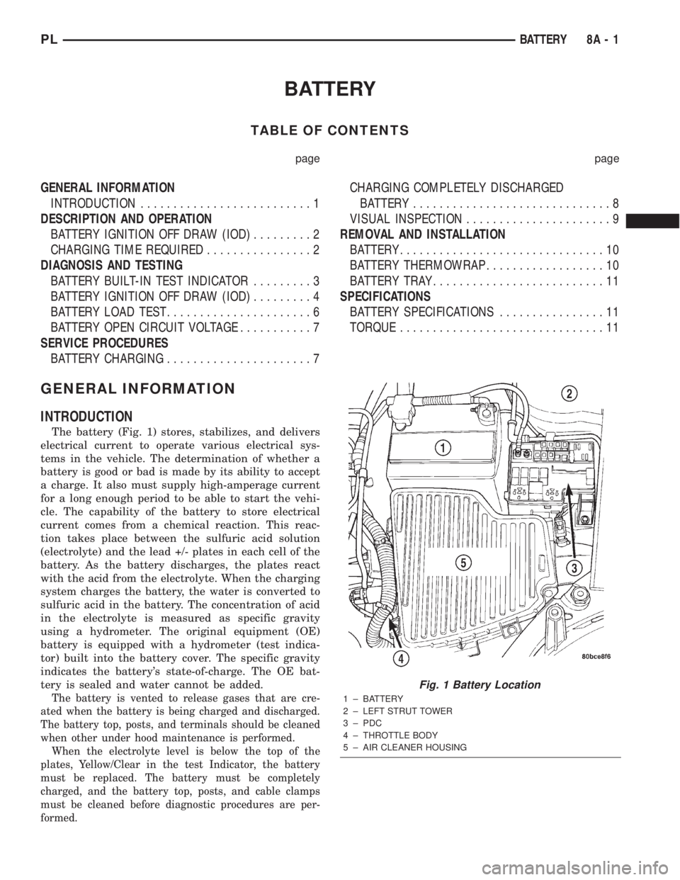
The battery (Fig. 1) stores, stabilizes, and delivers
electrical current to operate various electrical sys-
tems in the vehicle. The determination of whether a
battery is good or bad is made by its ability to accept
a charge. It also must supply high-amperage current
for a long enough period to be able to start the vehi-
cle. The capability of the battery to store electrical
current comes from a chemical reaction. This reac-
tion takes place between the sulfuric acid solution
(electrolyte) and the lead +/- plates in each cell of the
battery. As the battery discharges, the plates react
with the acid from the electrolyte. When the charging
system charges the battery, the water is converted to
sulfuric acid in the battery. The concentration of acid
in the electrolyte is measured as specific gravity
using a hydrometer. The original equipment (OE)
battery is equipped with a hydrometer (test indica-
tor) built into the battery cover. The specific gravity
indicates the battery's state-of-charge. The OE bat-
tery is sealed and water cannot be added.
The battery is vented to release gases that are cre-
ated when the battery is being charged and discharged.
The battery top, posts, and terminals should be cleaned
when other under hood maintenance is performed.
When the electrolyte level is below the top of the
plates, Yellow/Clear in the test Indicator, the battery
must be replaced. The battery must be completely
charged, and the battery top, posts, and cable clamps
must be cleaned before diagnostic procedures are per-
formed.
Fig. 1 Battery Location
1 ± BATTERY
2 ± LEFT STRUT TOWER
3 ± PDC
4 ± THROTTLE BODY
5 ± AIR CLEANER HOUSING
PLBATTERY 8A - 1
Page 219 of 1285
REMOVAL AND INSTALLATION
BATTERY
REMOVAL
WARNING: TO PROTECT THE HANDS FROM BAT-
TERY ACID, A SUITABLE PAIR OF HEAVY DUTY RUB-
BER GLOVES, NOT THE HOUSEHOLD TYPE, SHOULD
BE WORN WHEN REMOVING OR SERVICING A BAT-
TERY. SAFETY GLASSES ALSO SHOULD BE WORN.
(1) Make sure ignition switch is in OFF position
and all accessories are OFF.
(2) Open hood.
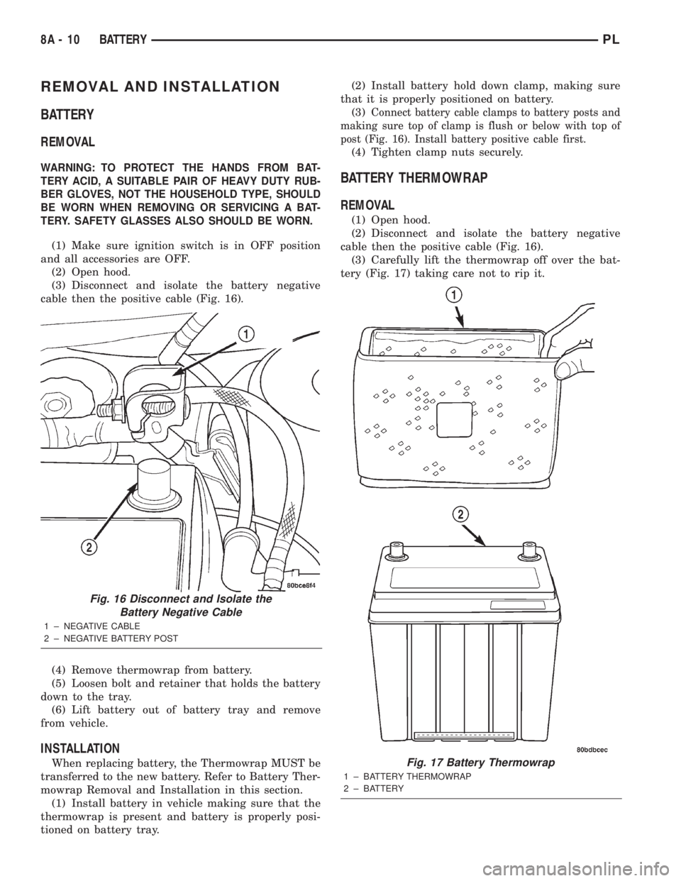
(3) Disconnect and isolate the battery negative
cable then the positive cable (Fig. 16).
(4) Remove thermowrap from battery.
(5) Loosen bolt and retainer that holds the battery
down to the tray.
(6) Lift battery out of battery tray and remove
from vehicle.
INSTALLATION
When replacing battery, the Thermowrap MUST be
transferred to the new battery. Refer to Battery Ther-
mowrap Removal and Installation in this section.
(1) Install battery in vehicle making sure that the
thermowrap is present and battery is properly posi-
tioned on battery tray.(2) Install battery hold down clamp, making sure
that it is properly positioned on battery.
(3)
Connect battery cable clamps to battery posts and
making sure top of clamp is flush or below with top of
post (Fig. 16). Install battery positive cable first.
(4) Tighten clamp nuts securely.
BATTERY THERMOWRAP
REMOVAL
(1) Open hood.
(2) Disconnect and isolate the battery negative
cable then the positive cable (Fig. 16).
(3) Carefully lift the thermowrap off over the bat-
tery (Fig. 17) taking care not to rip it.
Fig. 16 Disconnect and Isolate the
Battery Negative Cable
1 ± NEGATIVE CABLE
2 ± NEGATIVE BATTERY POST
Fig. 17 Battery Thermowrap
1 ± BATTERY THERMOWRAP
2 ± BATTERY
8A - 10 BATTERYPL
Page 306 of 1285
DIAGNOSIS AND TESTING
WINDSHIELD WASHER SYSTEM
Whenever a windshield washer malfunction occurs,
first verify that the windshield washer wire harnessis properly connected to all connectors before starting
normal diagnosis and repair procedures. Refer to
Windshield Washer System Test table.
WINDSHIELD WASHER SYSTEM TEST
CONDITION POSSIBLE CAUSE CORRECTION
PUMP RUNS NO FLUID
FLOWING.1. NO FLUID IN THE
RESERVOIR.
2. NOZZLE PLUGGED
OR FROZEN.
3. BROKEN, LOOSE OR
PINCHED HOSE.
4. FAULTY PUMP.1. FILL RESERVOIR.
2. THAW AND CHECK FLOW IF BLOCKED
3. CHECK FLOW THROUGH HOSE CONNECTIONS.
4. APPLY BATTERY VOLTAGE TO MOTOR
TERMINALS, REPLACE IF PUMP DOES NOT RUN.
SYSTEM OPERATES
INTERMITTENTLY.1. LOOSE WIRE
CONNECTION.
2. FAULTY SWITCH.1. CHECK WIRE CONNECTIONS.
2. DISCONNECT WIRE HARNESS USE
VOLTMETER TO CHECK SWITCH.
SYSTEM OUTPUT IS
LOW.1. PINCHED HOSE.
2. HOSE BLOCKED.1. CHECK FLOW THROUGH HOSE CONNECTION.
2. DISCONNECT HOSE AT NOZZLE AND Y
CONNECTOR CHECK FOR FLOW. REPLACE ASS
NECESSARY.
REMOVAL AND INSTALLATION
WINDSHIELD WASHER HOSE
REMOVAL
For damaged or plugged windshield washer hose,
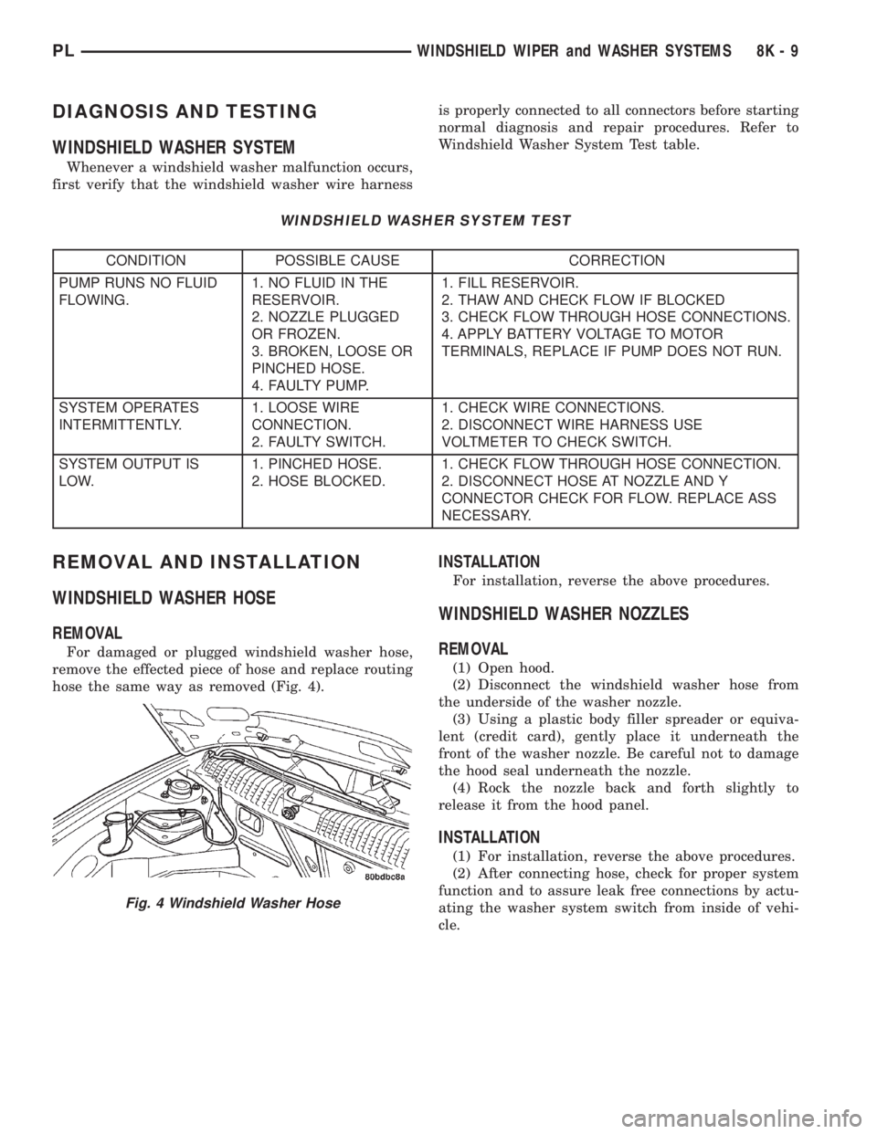
remove the effected piece of hose and replace routing
hose the same way as removed (Fig. 4).
INSTALLATION
For installation, reverse the above procedures.
WINDSHIELD WASHER NOZZLES
REMOVAL
(1) Open hood.
(2) Disconnect the windshield washer hose from
the underside of the washer nozzle.
(3) Using a plastic body filler spreader or equiva-
lent (credit card), gently place it underneath the
front of the washer nozzle. Be careful not to damage
the hood seal underneath the nozzle.
(4) Rock the nozzle back and forth slightly to
release it from the hood panel.
INSTALLATION
(1) For installation, reverse the above procedures.
(2) After connecting hose, check for proper system
function and to assure leak free connections by actu-
ating the washer system switch from inside of vehi-
cle.
Fig. 4 Windshield Washer Hose
PLWINDSHIELD WIPER and WASHER SYSTEMS 8K - 9
Page 314 of 1285
LAMP BULB SERVICE
TABLE OF CONTENTS
page page
DESCRIPTION AND OPERATION
BULB...................................7
REMOVAL AND INSTALLATION
HEADLAMP BULB.........................7
FOG LAMP BULB..........................8
PARK AND TURN SIGNAL LAMP BULB.........8
FRONT SIDE MARKER LAMP BULB...........9
CENTER HIGH MOUNTED STOP LAMP BULB....9
TAIL, STOP, BACK-UP AND TURN SIGNAL
LAMP BULB............................9LICENSE PLATE LAMP BULB...............10
UNDERHOOD LAMP BULB.................10
REAR CARGO LAMP BULB.................10
DOME LAMP BULB.......................10
TRANSAXLE RANGE INDICATOR LAMP BULB . . 10
GLOVE BOX LAMP BULB...................11
FLOOR CONSOLE LAMP BULB..............11
VISOR VANITY LAMP BULB.................11
DESCRIPTION AND OPERATION
BULB
The electric light bulb is a source of electromag-
netic radiation which generates light. Vehicles use
many different types of bulbs:
²Headlamp bulb
²Fog Lamp bulb
²Tail Lamp bulb
²Stop Lamp bulb
²Turn Signal bulb
²Back up Lamp bulb
²Dome Lamp bulb
²Transaxle Range Indicator Lamp bulb (PRNDL)
²Glove Box Lamp bulb
²Floor Console Lamp bulb
²Rear Cargo Lamp bulb
²Visor Vanity Lamp bulb
²Underhood Lamp bulb
²etc.
REMOVAL AND INSTALLATION
HEADLAMP BULB
REMOVAL
(1) Release hood latch and open hood.
(2) Remove screws attaching headlamp module to
upper crossmember.
(3) Remove headlamp module from vehicle.
(4) Disconnect wire connector from back of head-
lamp bulb.
(5) Rotate retaining ring counterclockwise one
quarter turn.
(6) Remove retaining ring from headlamp module.
(7) Remove bulb from headlamp module (Fig. 1).
INSTALLATION
CAUTION: Do not touch the glass of halogen bulbs
with fingers or other possibly oily surface, reduced
bulb life will result.
(1) Install bulb into headlamp module.
(2) Install retaining ring to headlamp module.
(3) Rotate retaining ring clockwise one quarter
turn.
(4) Connect wire connector to the back of head-
lamp bulb.
(5) Place headlamp module in position.
(6) Install screws attaching headlamp module to
upper crossmember.
(7) Close hood.
PLLAMPS 8L - 7
Page 315 of 1285
FOG LAMP BULB
REMOVAL
(1) Remove nuts attaching fog lamp to fascia.
(2) Disconnect wire connector from fog lamp.
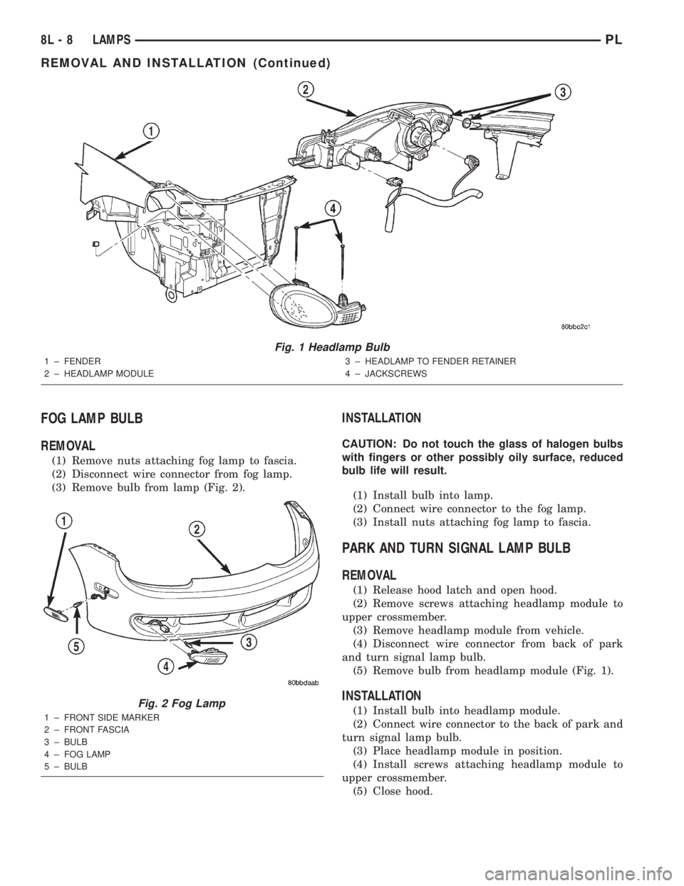
(3) Remove bulb from lamp (Fig. 2).
INSTALLATION
CAUTION: Do not touch the glass of halogen bulbs
with fingers or other possibly oily surface, reduced
bulb life will result.
(1) Install bulb into lamp.
(2) Connect wire connector to the fog lamp.
(3) Install nuts attaching fog lamp to fascia.
PARK AND TURN SIGNAL LAMP BULB
REMOVAL
(1) Release hood latch and open hood.
(2) Remove screws attaching headlamp module to
upper crossmember.
(3) Remove headlamp module from vehicle.
(4) Disconnect wire connector from back of park
and turn signal lamp bulb.
(5) Remove bulb from headlamp module (Fig. 1).
INSTALLATION
(1) Install bulb into headlamp module.
(2) Connect wire connector to the back of park and
turn signal lamp bulb.
(3) Place headlamp module in position.
(4) Install screws attaching headlamp module to
upper crossmember.
(5) Close hood.
Fig. 1 Headlamp Bulb
1 ± FENDER
2 ± HEADLAMP MODULE3 ± HEADLAMP TO FENDER RETAINER
4 ± JACKSCREWS
Fig. 2 Fog Lamp
1 ± FRONT SIDE MARKER
2 ± FRONT FASCIA
3 ± BULB
4 ± FOG LAMP
5 ± BULB
8L - 8 LAMPSPL
REMOVAL AND INSTALLATION (Continued)
Page 317 of 1285
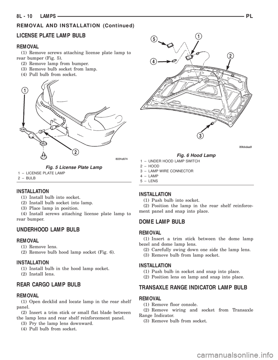
LICENSE PLATE LAMP BULB
REMOVAL
(1) Remove screws attaching license plate lamp to
rear bumper (Fig. 5).
(2) Remove lamp from bumper.
(3) Remove bulb socket from lamp.
(4) Pull bulb from socket.
INSTALLATION
(1) Install bulb into socket.
(2) Install bulb socket into lamp.
(3) Place lamp in position.
(4) Install screws attaching license plate lamp to
rear bumper.
UNDERHOOD LAMP BULB
REMOVAL
(1) Remove lens.
(2) Remove bulb hood lamp socket (Fig. 6).
INSTALLATION
(1) Install bulb in the hood lamp socket.
(2) Install lens.
REAR CARGO LAMP BULB
REMOVAL
(1) Open decklid and locate lamp in the rear shelf
panel.
(2) Insert a trim stick or small flat blade between
the lamp lens and rear shelf reinforcement panel.
(3) Pry the lamp lens downward.
(4) Pull bulb from socket.
INSTALLATION
(1) Push bulb into socket.
(2) Position the lamp in the rear shelf reinforce-
ment panel and snap into place.
DOME LAMP BULB
REMOVAL
(1) Insert a trim stick between the dome lamp
bezel and dome lamp lens.
(2) Carefully swing down one side the lamp lens.
(3) Remove bulb from lamp socket.
INSTALLATION
(1) Push bulb in socket and snap into place.
(2) Position lens on lamp and snap into place.
TRANSAXLE RANGE INDICATOR LAMP BULB
REMOVAL
(1) Remove floor console.
(2) Remove wiring and socket from Transaxle
Range Indicator.
(3) Remove bulb from socket.
Fig. 5 License Plate Lamp
1 ± LICENSE PLATE LAMP
2 ± BULB
Fig. 6 Hood Lamp
1 ± UNDER HOOD LAMP SWITCH
2 ± HOOD
3 ± LAMP WIRE CONNECTOR
4 ± LAMP
5 ± LENS
8L - 10 LAMPSPL
REMOVAL AND INSTALLATION (Continued)
Page 319 of 1285
LAMP SERVICE
TABLE OF CONTENTS
page page
DESCRIPTION AND OPERATION
LAMP ASSEMBLIES.......................12
REMOVAL AND INSTALLATION
HEADLAMP MODULE.....................12
FOG LAMP..............................13
PARK AND TURN SIGNAL LAMP BULB........13
FRONT SIDE MARKER LAMP...............13
CENTER HIGH MOUNTED STOP LAMP
(CHMSL)..............................14TAIL, STOP AND TURN SIGNAL LAMP........14
LICENSE PLATE LAMP....................14
UNDERHOOD LAMP......................14
REAR CARGO LAMP......................15
DOME LAMP............................15
GLOVE BOX LAMP BULB..................15
FLOOR CONSOLE LAMP BULB..............15
VISOR VANITY LAMP......................15
DESCRIPTION AND OPERATION
LAMP ASSEMBLIES
The lamp assemblies or modules generally consist
of a housing, reflector(s) and lens that directs a light
source. Vehicles use many different types of lamps:
²Headlamp
²Fog Lamp
²Tail Lamp
²Stop Lamp
²Turn Signal Lamp
²Back up Lamp
²Dome Lamp
²Transaxle Range Indicator Lamp (PRNDL)
²Glove Box Lamp
²Floor Console Lamp
²Rear Cargo Lamp
²Visor Vanity Lamp
²Underhood Lamp
²etc.
REMOVAL AND INSTALLATION
HEADLAMP MODULE
REMOVAL
(1) Release hood latch and open hood.
(2) Remove screws attaching headlamp module to
upper crossmember.
(3) Remove headlamp module from vehicle.
(4) Disconnect wire connectors from back of head-
lamp module.
(5) Remove headlamp module (Fig. 1).
INSTALLATION
CAUTION: Do not touch the glass of halogen bulbs
with fingers or other possibly oily surface, reduced
bulb life will result.
(1) Connect wire connectors to the back of head-
lamp module.
(2) Place headlamp module in position.
(3) Install screws attaching headlamp module to
upper crossmember.
(4) Close hood.
8L - 12 LAMPSPL