DODGE NEON SRT 2004 2.G Owners Manual
Manufacturer: DODGE, Model Year: 2004, Model line: NEON SRT, Model: DODGE NEON SRT 2004 2.GPages: 200, PDF Size: 3.23 MB
Page 161 of 200
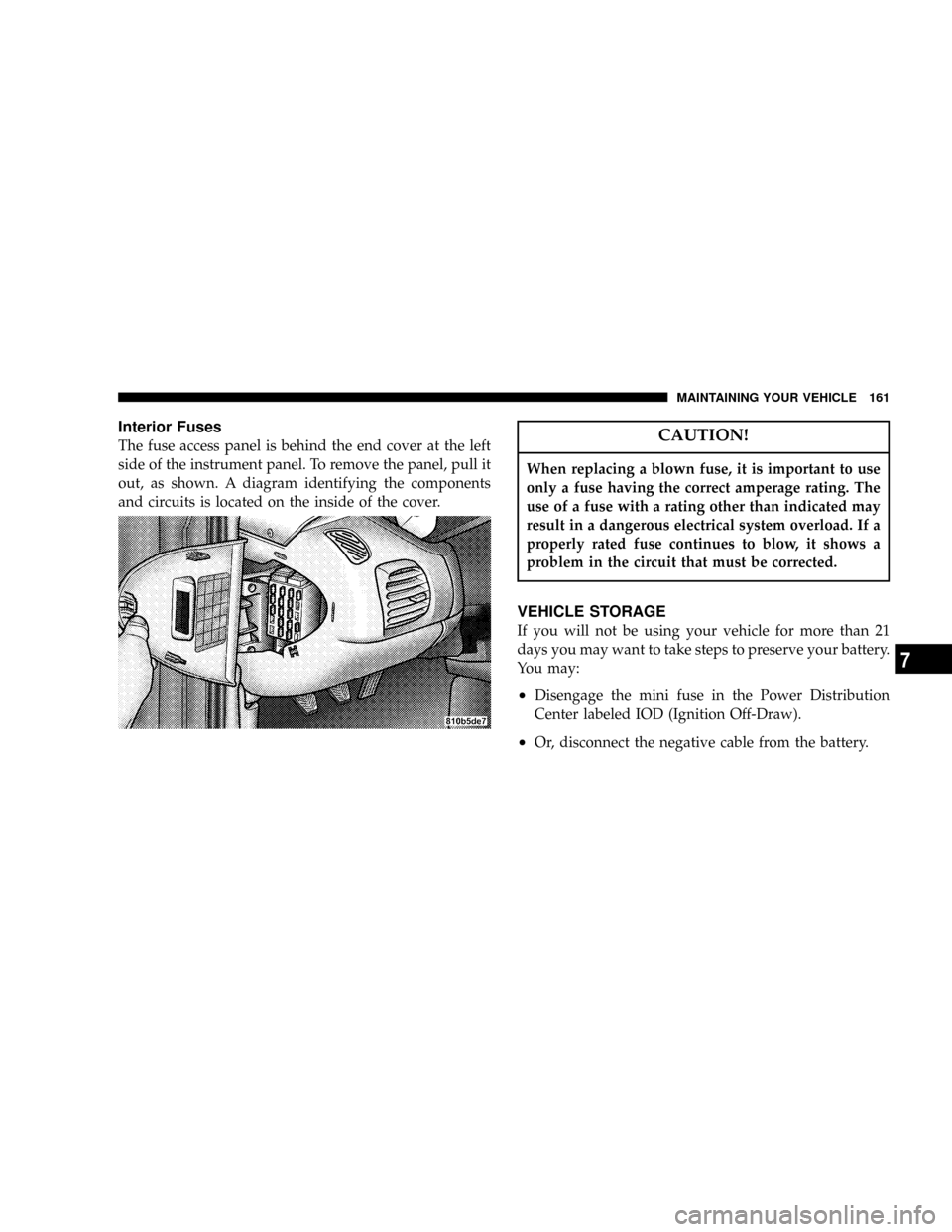
Interior Fuses
The fuse access panel is behind the end cover at the left
side of the instrument panel. To remove the panel, pull it
out, as shown. A diagram identifying the components
and circuits is located on the inside of the cover.CAUTION!
When replacing a blown fuse, it is important to use
only a fuse having the correct amperage rating. The
use of a fuse with a rating other than indicated may
result in a dangerous electrical system overload. If a
properly rated fuse continues to blow, it shows a
problem in the circuit that must be corrected.
VEHICLE STORAGE
If you will not be using your vehicle for more than 21
days you may want to take steps to preserve your battery.
You may:
²Disengage the mini fuse in the Power Distribution
Center labeled IOD (Ignition Off-Draw).
²Or, disconnect the negative cable from the battery.
MAINTAINING YOUR VEHICLE 161
7
Page 162 of 200

REPLACEMENT BULBS
LIGHT BULBS Ð Inside Bulb No.
ABS Indicator.......................... LED
Airbag Indicator........................ LED
Brake System Warning Indicator............. LED
Climate Controls........................ LED
Console Gear Selector...................PC194
Dome Light............................T579
Glove Box............................PC194
Front Fog Indicator...................... LED
High Beam Indicator....................PC194
Instrument Cluster Illumination............PC194
Low Fuel Indicator....................... LED
Low Oil Pressure Indicator................. LED
Rear Cargo............................T906
Seat Belt Indicator....................... LED
Security Alarm Indicator................... LED
Malfunction Indicator Light................ LED
TRAC OFF Indicator..................... LED
Turn Signal Indicator....................PC194
Voltage Indicator........................ LEDAll the inside bulbs are brass or glass wedge base.
Aluminum base bulbs are not approved and should not
be used for replacement.
LIGHTS BULBS Ð Outside Bulb No.
Headlight.............................9007
Front Park/Turn Signal Light............4157NAK
Front Side Marker Light.................... 168
Front Fog Light......................9145/H10
Center High Mounted Stop Light
(CHMSL).........................921±W16W
Rear Tail/Stop/Turn Signal Light......3157±P27/7W
Backup Light......................921±W16W
License Light........................... 168
162 MAINTAINING YOUR VEHICLE
Page 163 of 200
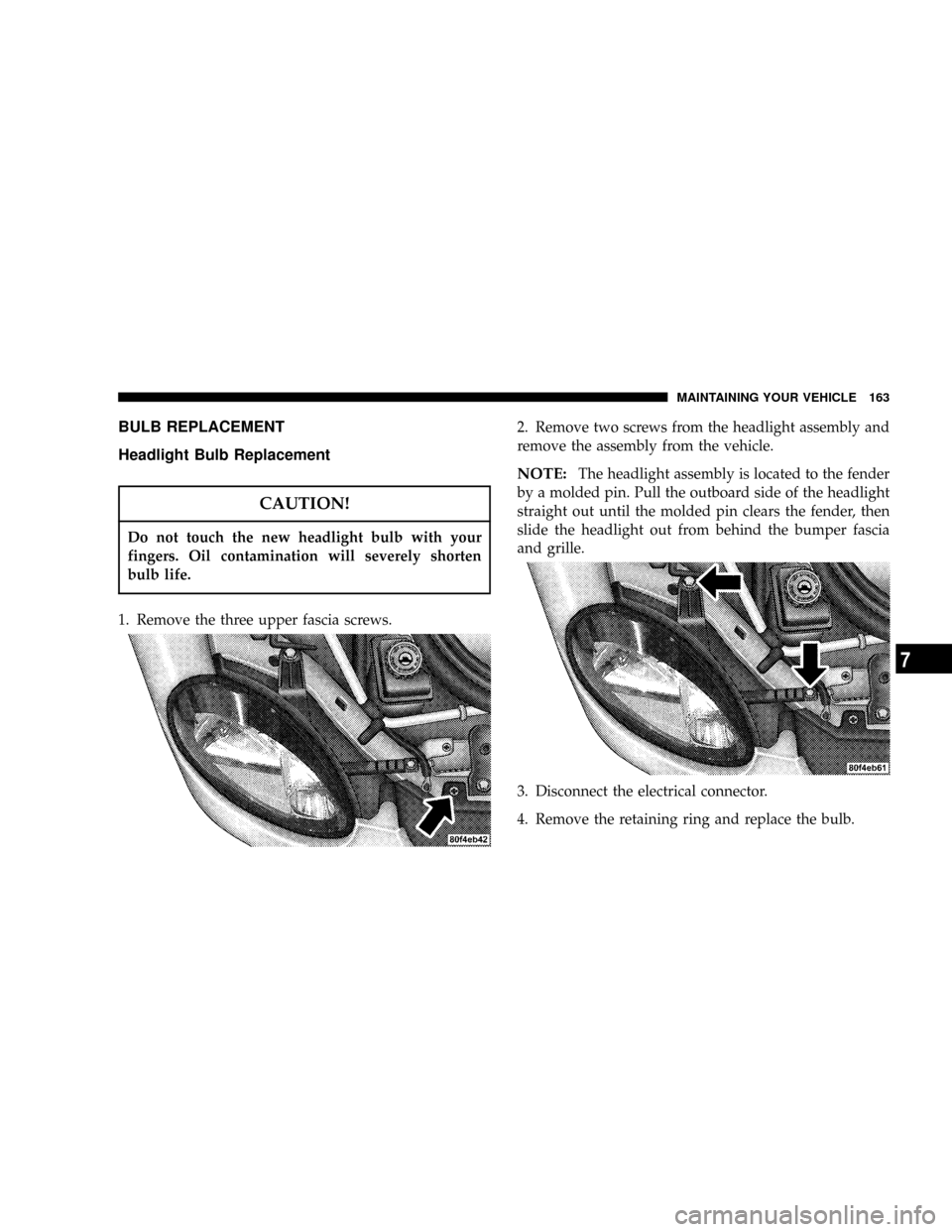
BULB REPLACEMENT
Headlight Bulb Replacement
CAUTION!
Do not touch the new headlight bulb with your
fingers. Oil contamination will severely shorten
bulb life.
1. Remove the three upper fascia screws.2. Remove two screws from the headlight assembly and
remove the assembly from the vehicle.
NOTE:The headlight assembly is located to the fender
by a molded pin. Pull the outboard side of the headlight
straight out until the molded pin clears the fender, then
slide the headlight out from behind the bumper fascia
and grille.
3. Disconnect the electrical connector.
4. Remove the retaining ring and replace the bulb.
MAINTAINING YOUR VEHICLE 163
7
Page 164 of 200

Front Park/Turn Signal Lights
1. Remove the headlight assembly
2. Twist the bulb socket 1/4 turn and remove.
3. Pull the bulb from the socket and replace.
Front Sidemarker Light
1. Remove the screws and push-pins from the front
fender splash shield.
2. Reach between the fender and the splash shield, grasp
the bulb and socket assembly and turn it counterclock-
wise. Remove the bulb and socket assembly from the
light housing.
3. Pull the bulb out of the socket and replace the bulb.
Reinstall the bulb and socket assembly and replace the
fender splash shield.
Tail/Stop, Rear Turn Signals and Back-up Lights
1. Open the trunk and move the trunk liner away from
the rear light mounting area.
2. Twist the bulb socket 1/4 turn to remove it from the
housing.
3. Pull bulb from socket and replace
Center High Mounted Stop Light
1. Twist the socket 1/4 turn and remove it from the
housing.
2. Pull the bulb out of the socket and replace.
164 MAINTAINING YOUR VEHICLE
Page 165 of 200
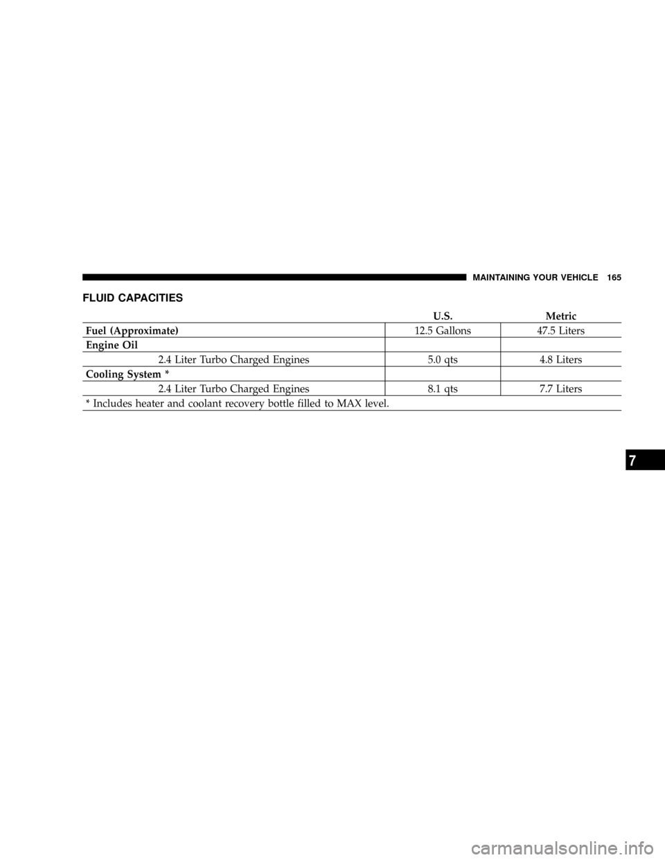
FLUID CAPACITIES
U.S. Metric
Fuel (Approximate)12.5 Gallons 47.5 Liters
Engine Oil
2.4 Liter Turbo Charged Engines 5.0 qts 4.8 Liters
Cooling System *
2.4 Liter Turbo Charged Engines 8.1 qts 7.7 Liters
* Includes heater and coolant recovery bottle filled to MAX level.
MAINTAINING YOUR VEHICLE 165
7
Page 166 of 200
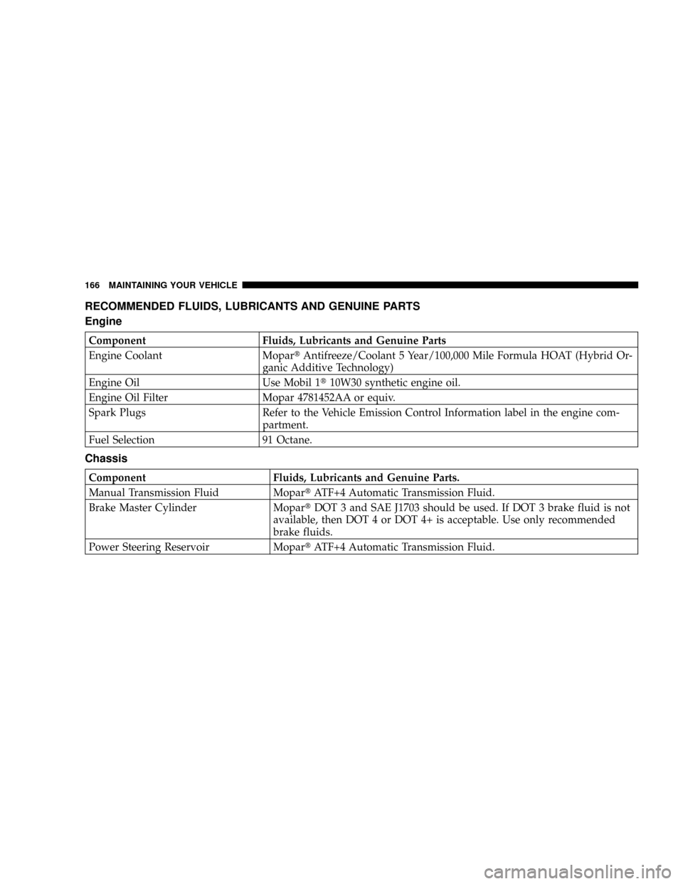
RECOMMENDED FLUIDS, LUBRICANTS AND GENUINE PARTS
Engine
Component Fluids, Lubricants and Genuine Parts
Engine Coolant MopartAntifreeze/Coolant 5 Year/100,000 Mile Formula HOAT (Hybrid Or-
ganic Additive Technology)
Engine Oil Use Mobil 1t10W30 synthetic engine oil.
Engine Oil Filter Mopar 4781452AA or equiv.
Spark Plugs Refer to the Vehicle Emission Control Information label in the engine com-
partment.
Fuel Selection 91 Octane.
Chassis
Component Fluids, Lubricants and Genuine Parts.
Manual Transmission Fluid MopartATF+4 Automatic Transmission Fluid.
Brake Master Cylinder MopartDOT 3 and SAE J1703 should be used. If DOT 3 brake fluid is not
available, then DOT 4 or DOT 4+ is acceptable. Use only recommended
brake fluids.
Power Steering Reservoir MopartATF+4 Automatic Transmission Fluid.
166 MAINTAINING YOUR VEHICLE
Page 167 of 200
MAINTENANCE SCHEDULES
CONTENTS
mEmission Control System Maintenance......168
mMaintenance Schedule..................168NSchedule ªBº........................171
NSchedule ªAº........................178
8
M
A
I
N
T
E
N
A
N
C
E
S
C
H
E
D
U
L
E
S
Page 168 of 200
EMISSION CONTROL SYSTEM MAINTENANCE
The ªScheduledº maintenance services, listed inbold
typemust be done at the times or mileages specified to
assure the continued proper functioning of the emission
control system. These, and all other maintenance services
included in this manual, should be done to provide best
vehicle performance and reliability. More frequent main-
tenance may be needed for vehicles in severe operating
conditions such as dusty areas and very short trip
driving.
Inspection and service also should be done any time a
malfunction is suspected.
NOTE:Maintenance, replacement, or repair of the
emission control devices and systems on your vehicle
may be performed by any automotive repair establish-
ment or individual using any automotive part which has
been certified pursuant to U.S. EPA or, in the State of
California, California Air Resources Board regulations.
MAINTENANCE SCHEDULE
There are three maintenance schedules that showre-
quiredservice for your vehicle.
First is ScheduleªBº. It is for vehicles that are operated
under the conditions that are listed below and at the
beginning of the schedule.
²Day or night temperatures are below 32É F (0É C).
²Stop and go driving.
²Extensive engine idling.
²Driving in dusty conditions.
²Short trips of less than 10 miles (16 km).
²More than 50% of your driving is at sustained high
speeds during hot weather, above 90É F (32É C).
²Trailer towing.²
²Taxi, police, or delivery service (commercial service).²
²Off-road or desert operation.
²If equipped for and operating with E-85 (ethanol)
fuel.
168 MAINTENANCE SCHEDULES
8
M
A
I
N
T
E
N
A
N
C
E
S
C
H
E
D
U
L
E
S
Page 169 of 200
NOTE:IfANYof these apply to you then change your
engine oil every 3,000 miles (5 000 km) or 3 months,
whichever comes first and follow schedule ªBº of the
9Maintenance Schedules9section of this manual.
NOTE:Most vehicles are operated under the conditions
listed for Schedule9B9.
Second is ScheduleªAº. It is for vehicles that are not
operated under any of the conditions listed under Sched-
ule9B9
Use the schedule that best describes your driving condi-
tions. Where time and mileage are listed, follow the
interval that occurs first.
CAUTION!
Failure to perform the required maintenance items
may result in damage to the vehicle.
At Each Stop for Fuel
²
Check the engine oil level about 5 minutes after a fully
warmed engine is shut off. Checking the oil level while
the vehicle is on level ground will improve the accu-
racy of the oil level reading. Add oil only when the
level is at or below the ADD or MIN mark.
²Check the windshield washer solvent and add if
required.
Once a Month
²
Check tire pressure and look for unusual wear or
damage.
²Inspect the battery and clean and tighten the terminals
as required.
²Check the fluid levels of coolant reservoir, brake
master cylinder and transaxle and add as needed.
²Check all lights and all other electrical items for correct
operation.
²Check rubber seals on each side of the radiator for
proper fit.
MAINTENANCE SCHEDULES 169
8
M
A
I
N
T
E
N
A
N
C
E
S
C
H
E
D
U
L
E
S
Page 170 of 200
At Each Oil Change
²
Change the engine oil filter.
²Inspect the exhaust system.
²Inspect the brake hoses.
²Inspect the CV joints and front suspension compo-
nents.
²Check the manual transaxle fluid level and fill plug
condition.
²Check the coolant level, hoses, and clamps.
²Rotate the tires at each oil change interval shown on
SCHEDULE ªAº 5,000 miles (8 000 km), or every other
interval shown on SCHEDULE ªBº 6,000 miles (10,000
km).
170 MAINTENANCE SCHEDULES
8
M
A
I
N
T
E
N
A
N
C
E
S
C
H
E
D
U
L
E
S