Coil DODGE RAM 1500 1998 2.G Owners Manual
[x] Cancel search | Manufacturer: DODGE, Model Year: 1998, Model line: RAM 1500, Model: DODGE RAM 1500 1998 2.GPages: 2627
Page 1382 of 2627
INSTALLATION
(1) Position the oil pump onto the crankshaft and
install one oil pump retaining bolts.
(2) Position the primary timing chain tensioner
and install three retaining bolts.
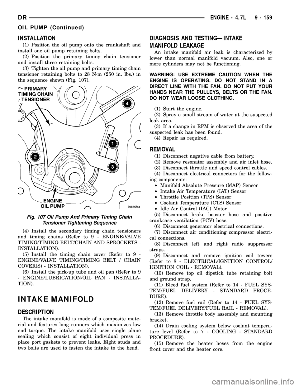
(3) Tighten the oil pump and primary timing chain
tensioner retaining bolts to 28 N´m (250 in. lbs.) in
the sequence shown (Fig. 107).
(4) Install the secondary timing chain tensioners
and timing chains (Refer to 9 - ENGINE/VALVE
TIMING/TIMING BELT/CHAIN AND SPROCKETS -
INSTALLATION).
(5) Install the timing chain cover (Refer to 9 -
ENGINE/VALVE TIMING/TIMING BELT / CHAIN
COVER(S) - INSTALLATION).
(6) Install the pick-up tube and oil pan (Refer to 9
- ENGINE/LUBRICATION/OIL PAN - INSTALLA-
TION).
INTAKE MANIFOLD
DESCRIPTION
The intake manifold is made of a composite mate-
rial and features long runners which maximizes low
end torque. The intake manifold uses single plane
sealing which consist of eight individual press in
place port gaskets to prevent leaks. Eight studs and
two bolts are used to fasten the intake to the head.
DIAGNOSIS AND TESTINGÐINTAKE
MANIFOLD LEAKAGE
An intake manifold air leak is characterized by
lower than normal manifold vacuum. Also, one or
more cylinders may not be functioning.
WARNING: USE EXTREME CAUTION WHEN THE
ENGINE IS OPERATING. DO NOT STAND IN A
DIRECT LINE WITH THE FAN. DO NOT PUT YOUR
HANDS NEAR THE PULLEYS, BELTS OR THE FAN.
DO NOT WEAR LOOSE CLOTHING.
(1) Start the engine.
(2) Spray a small stream of water at the suspected
leak area.
(3) If a change in RPM is observed the area of the
suspected leak has been found.
(4) Repair as required.
REMOVAL
(1) Disconnect negative cable from battery.
(2) Remove resonator assembly and air inlet hose.
(3) Disconnect throttle and speed control cables.
(4) Disconnect electrical connectors for the follow-
ing components:
²Manifold Absolute Pressure (MAP) Sensor
²Intake Air Temperature (IAT) Sensor
²Throttle Position (TPS) Sensor
²Coolant Temperature (CTS) Sensor
²Idle Air Control (IAC) Motor
(5) Disconnect brake booster hose and positive
crankcase ventilation (PCV) hose.
(6) Disconnect generator electrical connections.
(7) Disconnect air conditioning compressor electri-
cal connections.
(8) Disconnect left and right radio suppressor
straps.
(9) Disconnect and remove ignition coil towers
(Refer to 8 - ELECTRICAL/IGNITION CONTROL/
IGNITION COIL - REMOVAL).
(10) Remove top oil dipstick tube retaining bolt
and ground strap.
(11) Bleed fuel system (Refer to 14 - FUEL SYS-
TEM/FUEL DELIVERY - STANDARD PROCE-
DURE).
(12) Remove fuel rail (Refer to 14 - FUEL SYS-
TEM/FUEL DELIVERY/FUEL RAIL - REMOVAL).
(13) Remove throttle body assembly and mounting
bracket.
(14) Drain cooling system below coolant tempera-
ture level (Refer to 7 - COOLING - STANDARD
PROCEDURE).
(15) Remove the heater hoses from the engine
front cover and the heater core.
Fig. 107 Oil Pump And Primary Timing Chain
Tensioner Tightening Sequence
DRENGINE - 4.7L 9 - 159
OIL PUMP (Continued)
Page 1383 of 2627
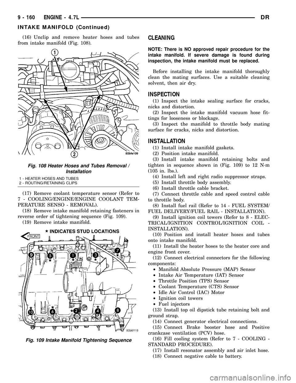
(16) Unclip and remove heater hoses and tubes
from intake manifold (Fig. 108).
(17) Remove coolant temperature sensor (Refer to
7 - COOLING/ENGINE/ENGINE COOLANT TEM-
PERATURE SENSO - REMOVAL).
(18) Remove intake manifold retaining fasteners in
reverse order of tightening sequence (Fig. 109).
(19) Remove intake manifold.CLEANING
NOTE: There is NO approved repair procedure for the
intake manifold. If severe damage is found during
inspection, the intake manifold must be replaced.
Before installing the intake manifold thoroughly
clean the mating surfaces. Use a suitable cleaning
solvent, then air dry.
INSPECTION
(1) Inspect the intake sealing surface for cracks,
nicks and distortion.
(2) Inspect the intake manifold vacuum hose fit-
tings for looseness or blockage.
(3) Inspect the manifold to throttle body mating
surface for cracks, nicks and distortion.
INSTALLATION
(1) Install intake manifold gaskets.
(2) Position intake manifold.
(3) Install intake manifold retaining bolts and
tighten in sequence shown in (Fig. 109) to 12 N´m
(105 in. lbs.).
(4) Install left and right radio suppressor straps.
(5) Install throttle body assembly.
(6) Install throttle cable bracket.
(7) Connect throttle cable and speed control cable
to throttle body.
(8) Install fuel rail (Refer to 14 - FUEL SYSTEM/
FUEL DELIVERY/FUEL RAIL - INSTALLATION).
(9) Install ignition coil towers (Refer to 8 - ELEC-
TRICAL/IGNITION CONTROL/IGNITION COIL -
INSTALLATION).
(10) Position and install heater hoses and tubes
onto intake manifold.
(11) Install the heater hoses to the heater core and
engine front cover.
(12) Connect electrical connectors for the following
components:
²Manifold Absolute Pressure (MAP) Sensor
²Intake Air Temperature (IAT) Sensor
²Throttle Position (TPS) Sensor
²Coolant Temperature (CTS) Sensor
²Idle Air Control (IAC) Motor
²Ignition coil towers
²Fuel injectors
(13) Install top oil dipstick tube retaining bolt and
ground strap.
(14) Connect generator electrical connections.
(15) Connect Brake booster hose and Positive
crankcase ventilation (PCV) hose.
(16) Fill cooling system (Refer to 7 - COOLING -
STANDARD PROCEDURE).
(17) Install resonator assembly and air inlet hose.
(18) Connect negative cable to battery.
Fig. 108 Heater Hoses and Tubes Removal /
Installation
1 - HEATER HOSES AND TUBES
2 - ROUTING/RETAINING CLIPS
Fig. 109 Intake Manifold Tightening Sequence
9 - 160 ENGINE - 4.7LDR
INTAKE MANIFOLD (Continued)
Page 1406 of 2627
DIAGNOSIS AND TESTING
DIAGNOSIS AND TESTING - ENGINE
DIAGNOSIS - INTRODUCTION
Engine diagnosis is helpful in determining the
causes of malfunctions not detected and remedied by
routine maintenance.
These malfunctions may be classified as either per-
formance (e.g., engine idles rough and stalls) or
mechanical (e.g., a strange noise).
(Refer to 9 - ENGINE - DIAGNOSIS AND TEST-
ING) - PERFORMANCE and (Refer to 9 - ENGINE -
DIAGNOSIS AND TESTING)ÐMECHANICAL for
possible causes and corrections of malfunctions.
(Refer to 14 - FUEL SYSTEM/FUEL DELIVERY -
DIAGNOSIS AND TESTING) and (Refer to 14 -
FUEL SYSTEM/FUEL INJECTION - DIAGNOSIS
AND TESTING) for the fuel system diagnosis.Additional tests and diagnostic procedures may be
necessary for specific engine malfunctions that can
not be isolated with the Service Diagnosis charts.
Information concerning additional tests and diagno-
sis is provided within the following diagnosis:
²Cylinder Compression Pressure Test (Refer to 9 -
ENGINE - DIAGNOSIS AND TESTING).
²Cylinder Combustion Pressure Leakage Test
(Refer to 9 - ENGINE - DIAGNOSIS AND TEST-
ING).
²Engine Cylinder Head Gasket Failure Diagnosis
(Refer to 9 - ENGINE/CYLINDER HEAD - DIAGNO-
SIS AND TESTING).
²Intake Manifold Leakage Diagnosis (Refer to 9 -
ENGINE/MANIFOLDS/INTAKE MANIFOLD -
DIAGNOSIS AND TESTING).
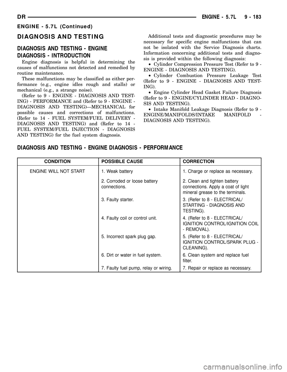
DIAGNOSIS AND TESTING - ENGINE DIAGNOSIS - PERFORMANCE
CONDITION POSSIBLE CAUSE CORRECTION
ENGINE WILL NOT START 1. Weak battery 1. Charge or replace as necessary.
2. Corroded or loose battery
connections.2. Clean and tighten battery
connections. Apply a coat of light
mineral grease to the terminals.
3. Faulty starter. 3. (Refer to 8 - ELECTRICAL/
STARTING - DIAGNOSIS AND
TESTING).
4. Faulty coil or control unit. 4. (Refer to 8 - ELECTRICAL/
IGNITION CONTROL/IGNITION COIL
- REMOVAL).
5. Incorrect spark plug gap. 5. (Refer to 8 - ELECTRICAL/
IGNITION CONTROL/SPARK PLUG -
CLEANING).
6. Dirt or water in fuel system. 6. Clean system and replace fuel
filter.
7. Faulty fuel pump, relay or wiring. 7. Repair or replace as necessary.
DRENGINE - 5.7L 9 - 183
ENGINE - 5.7L (Continued)
Page 1407 of 2627
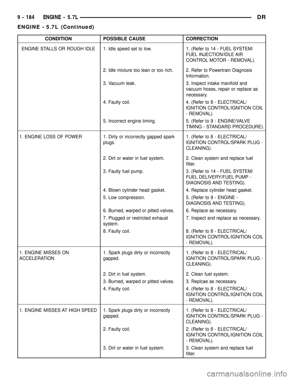
CONDITION POSSIBLE CAUSE CORRECTION
ENGINE STALLS OR ROUGH IDLE 1. Idle speed set to low. 1. (Refer to 14 - FUEL SYSTEM/
FUEL INJECTION/IDLE AIR
CONTROL MOTOR - REMOVAL).
2. Idle mixture too lean or too rich. 2. Refer to Powertrain Diagnosis
Information.
3. Vacuum leak. 3. Inspect intake manifold and
vacuum hoses, repair or replace as
necessary.
4. Faulty coil. 4. (Refer to 8 - ELECTRICAL/
IGNITION CONTROL/IGNITION COIL
- REMOVAL).
5. Incorrect engine timing. 5. (Refer to 9 - ENGINE/VALVE
TIMING - STANDARD PROCEDURE).
1. ENGINE LOSS OF POWER 1. Dirty or incorrectly gapped spark
plugs.1. (Refer to 8 - ELECTRICAL/
IGNITION CONTROL/SPARK PLUG -
CLEANING).
2. Dirt or water in fuel system. 2. Clean system and replace fuel
filter.
3. Faulty fuel pump. 3. (Refer to 14 - FUEL SYSTEM/
FUEL DELIVERY/FUEL PUMP -
DIAGNOSIS AND TESTING).
4. Blown cylinder head gasket. 4. Replace cylinder head gasket.
5. Low compression. 5. (Refer to 9 - ENGINE -
DIAGNOSIS AND TESTING).
6. Burned, warped or pitted valves. 6. Replace as necessary.
7. Plugged or restricted exhaust
system.7. Inspect and replace as necessary.
8. Faulty coil. 8. (Refer to 8 - ELECTRICAL/
IGNITION CONTROL/IGNITION COIL
- REMOVAL).
1. ENGINE MISSES ON
ACCELERATION1. Spark plugs dirty or incorrectly
gapped.1. (Refer to 8 - ELECTRICAL/
IGNITION CONTROL/SPARK PLUG -
CLEANING).
2. Dirt in fuel system. 2. Clean fuel system.
3. Burned, warped or pitted valves. 3. Replcae as necessary.
4. Faulty coil. 4. (Refer to 8 - ELECTRICAL/
IGNITION CONTROL/IGNITION COIL
- REMOVAL).
1. ENGINE MISSES AT HIGH SPEED 1. Spark plugs dirty or incorrectly
gapped.1. (Refer to 8 - ELECTRICAL/
IGNITION CONTROL/SPARK PLUG -
CLEANING).
2. Faulty coil. 2. (Refer to 8 - ELECTRICAL/
IGNITION CONTROL/IGNITION COIL
- REMOVAL).
3. Dirt or water in fuel system. 3. Clean system and replace fuel
filter.
9 - 184 ENGINE - 5.7LDR
ENGINE - 5.7L (Continued)
Page 1413 of 2627
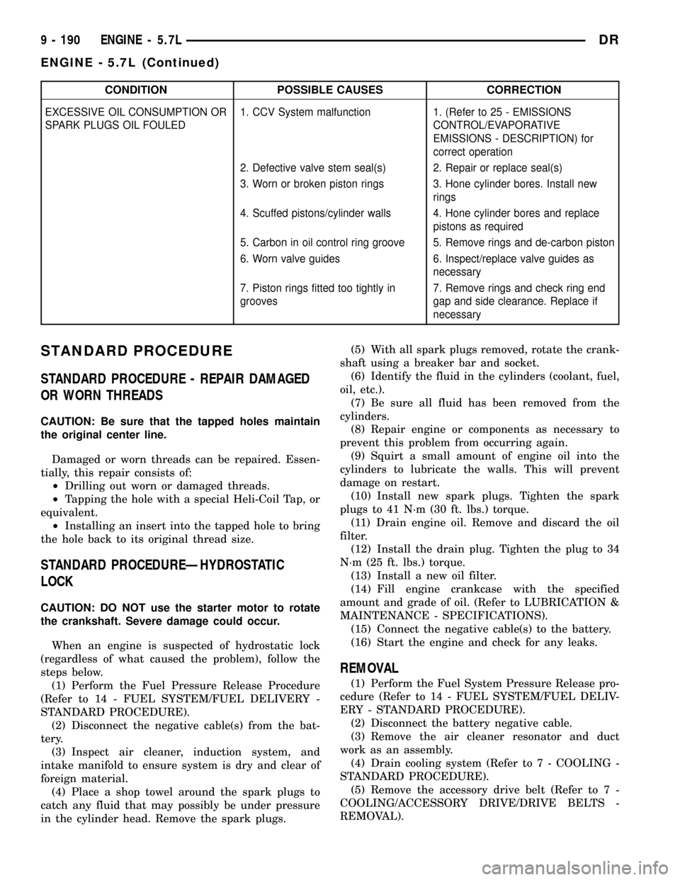
CONDITION POSSIBLE CAUSES CORRECTION
EXCESSIVE OIL CONSUMPTION OR
SPARK PLUGS OIL FOULED1. CCV System malfunction 1. (Refer to 25 - EMISSIONS
CONTROL/EVAPORATIVE
EMISSIONS - DESCRIPTION) for
correct operation
2. Defective valve stem seal(s) 2. Repair or replace seal(s)
3. Worn or broken piston rings 3. Hone cylinder bores. Install new
rings
4. Scuffed pistons/cylinder walls 4. Hone cylinder bores and replace
pistons as required
5. Carbon in oil control ring groove 5. Remove rings and de-carbon piston
6. Worn valve guides 6. Inspect/replace valve guides as
necessary
7. Piston rings fitted too tightly in
grooves7. Remove rings and check ring end
gap and side clearance. Replace if
necessary
STANDARD PROCEDURE
STANDARD PROCEDURE - REPAIR DAMAGED
OR WORN THREADS
CAUTION: Be sure that the tapped holes maintain
the original center line.
Damaged or worn threads can be repaired. Essen-
tially, this repair consists of:
²Drilling out worn or damaged threads.
²Tapping the hole with a special Heli-Coil Tap, or
equivalent.
²Installing an insert into the tapped hole to bring
the hole back to its original thread size.
STANDARD PROCEDUREÐHYDROSTATIC
LOCK
CAUTION: DO NOT use the starter motor to rotate
the crankshaft. Severe damage could occur.
When an engine is suspected of hydrostatic lock
(regardless of what caused the problem), follow the
steps below.
(1) Perform the Fuel Pressure Release Procedure
(Refer to 14 - FUEL SYSTEM/FUEL DELIVERY -
STANDARD PROCEDURE).
(2) Disconnect the negative cable(s) from the bat-
tery.
(3) Inspect air cleaner, induction system, and
intake manifold to ensure system is dry and clear of
foreign material.
(4) Place a shop towel around the spark plugs to
catch any fluid that may possibly be under pressure
in the cylinder head. Remove the spark plugs.(5) With all spark plugs removed, rotate the crank-
shaft using a breaker bar and socket.
(6) Identify the fluid in the cylinders (coolant, fuel,
oil, etc.).
(7) Be sure all fluid has been removed from the
cylinders.
(8) Repair engine or components as necessary to
prevent this problem from occurring again.
(9) Squirt a small amount of engine oil into the
cylinders to lubricate the walls. This will prevent
damage on restart.
(10) Install new spark plugs. Tighten the spark
plugs to 41 N´m (30 ft. lbs.) torque.
(11) Drain engine oil. Remove and discard the oil
filter.
(12) Install the drain plug. Tighten the plug to 34
N´m (25 ft. lbs.) torque.
(13) Install a new oil filter.
(14) Fill engine crankcase with the specified
amount and grade of oil. (Refer to LUBRICATION &
MAINTENANCE - SPECIFICATIONS).
(15) Connect the negative cable(s) to the battery.
(16) Start the engine and check for any leaks.
REMOVAL
(1) Perform the Fuel System Pressure Release pro-
cedure (Refer to 14 - FUEL SYSTEM/FUEL DELIV-
ERY - STANDARD PROCEDURE).
(2) Disconnect the battery negative cable.
(3) Remove the air cleaner resonator and duct
work as an assembly.
(4) Drain cooling system (Refer to 7 - COOLING -
STANDARD PROCEDURE).
(5) Remove the accessory drive belt (Refer to 7 -
COOLING/ACCESSORY DRIVE/DRIVE BELTS -
REMOVAL).
9 - 190 ENGINE - 5.7LDR
ENGINE - 5.7L (Continued)
Page 1418 of 2627
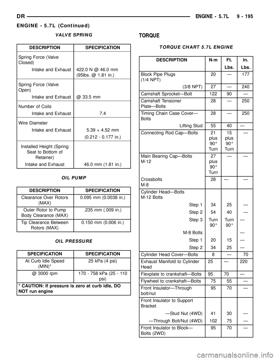
VALVE SPRING
DESCRIPTION SPECIFICATION
Spring Force (Valve
Closed)
Intake and Exhaust 422.0 N @ 46.0 mm
(95lbs. @ 1.81 in.)
Spring Force (Valve
Open)
Intake and Exhaust @ 33.5 mm
Number of Coils
Intake and Exhaust 7.4
Wire Diameter
Intake and Exhaust 5.39 ý 4.52 mm
(0.212 - 0.177 in.)
Installed Height (Spring
Seat to Bottom of
Retainer)
Intake and Exhaust 46.0 mm (1.81 in.)
OIL PUMP
DESCRIPTION SPECIFICATION
Clearance Over Rotors
(MAX)0.095 mm (0.0038 in.)
Outer Rotor to Pump
Body Clearance (MAX).235 mm (.009 in.)
Tip Clearance Between
Rotors (MAX)0.150 mm (0.006 in.)
OIL PRESSURE
SPECIFICATION SPECIFICATION
At Curb Idle Speed
(MIN)*25 kPa (4 psi)
@ 3000 rpm 170 - 758 kPa (25 - 110
psi)
* CAUTION: If pressure is zero at curb idle, DO
NOT run engine
TORQUE
TORQUE CHART 5.7L ENGINE
DESCRIPTION N´m Ft. In.
Lbs. Lbs.
Block Pipe Plugs
(1/4 NPT)20 Ð 177
(3/8 NPT) 27 Ð 240
Camshaft SprocketÐBolt 122 90 Ð
Camshaft Tensioner
PlateÐBolts28 Ð 250
Timing Chain Case CoverÐ
Bolts28 Ð 250
Lifting Stud 55 40 Ð
Connecting Rod CapÐBolts 21
plus
90É
Turn15
plus
90É
TurnÐ
Main Bearing CapÐBolts
M-1227
plus
90É
TurnÐÐ
Crossbolts
M-828 Ð Ð
Cylinder HeadÐBolts
M-12 Bolts
Step 1 34 25 Ð
Step 2 54 40 Ð
Step 3 Turn
90ÉTurn
90ÉÐ
M-8 Bolts Ð
Step 1 20 15 Ð
Step 2 34 25 Ð
Cylinder Head CoverÐBolts 8 Ð 70
Exhaust Manifold to Cylinder
Head25 Ð 220
Flexplate to crankshaftÐBolts 95 70 Ð
Flywheel to crankshaftÐBolts 75 55 Ð
Front InsulatorÐThrough
bolt/nut95 70 Ð
Front Insulator to Support
Bracket
ÐStud Nut (4WD) 41 30 Ð
ÐThrough Bolt/Nut (4WD) 102 75 Ð
Front Insulator to BlockÐ
Bolts (2WD)95 70 Ð
DRENGINE - 5.7L 9 - 195
ENGINE - 5.7L (Continued)
Page 1424 of 2627
CAUTION: The head gaskets are marked ªTOPº to
indicate which side goes up.
(4) Position cylinder heads onto head gaskets and
cylinder block.
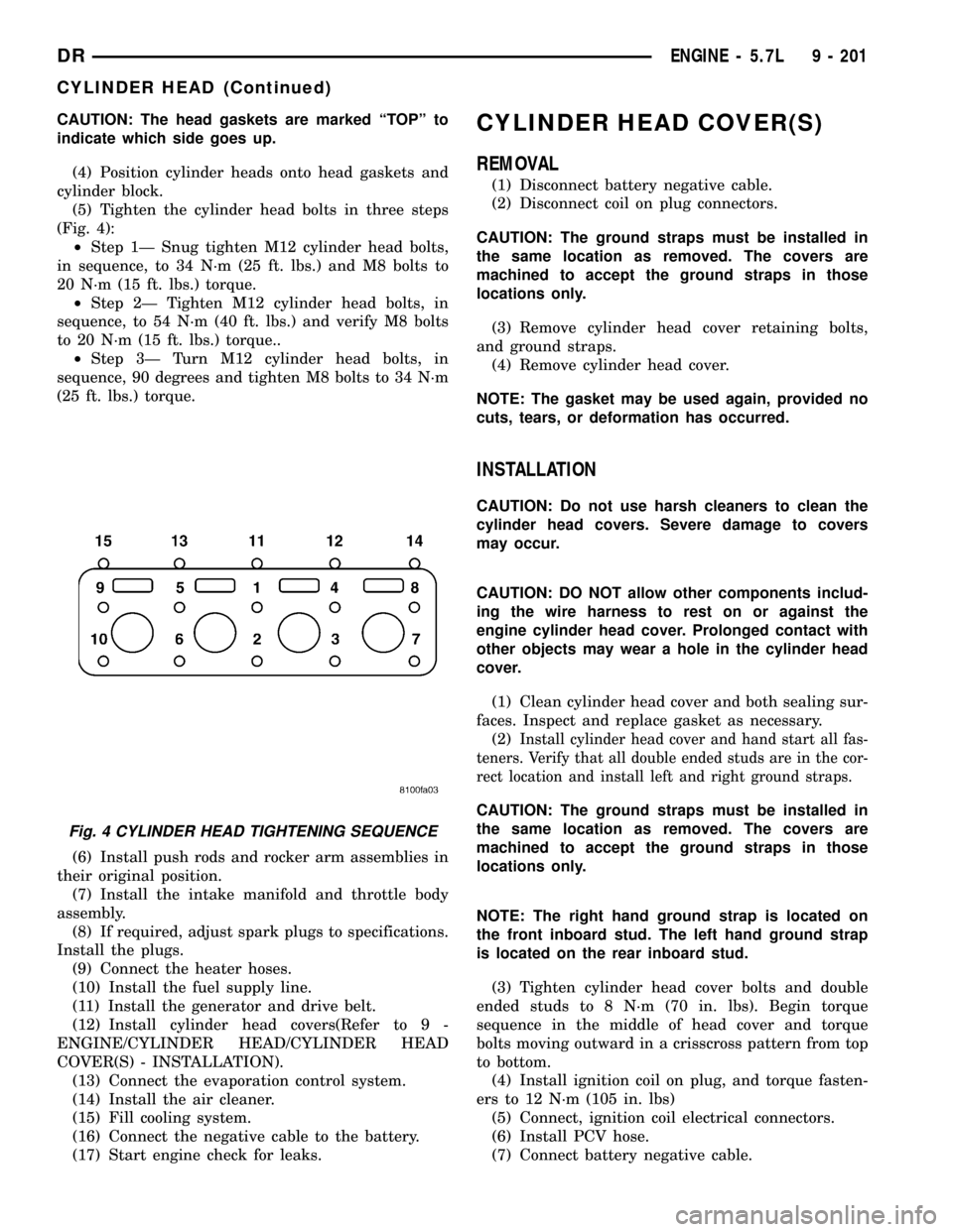
(5) Tighten the cylinder head bolts in three steps
(Fig. 4):
²Step 1Ð Snug tighten M12 cylinder head bolts,
in sequence, to 34 N´m (25 ft. lbs.) and M8 bolts to
20 N´m (15 ft. lbs.) torque.
²Step 2Ð Tighten M12 cylinder head bolts, in
sequence, to 54 N´m (40 ft. lbs.) and verify M8 bolts
to 20 N´m (15 ft. lbs.) torque..
²Step 3Ð Turn M12 cylinder head bolts, in
sequence, 90 degrees and tighten M8 bolts to 34 N´m
(25 ft. lbs.) torque.
(6) Install push rods and rocker arm assemblies in
their original position.
(7) Install the intake manifold and throttle body
assembly.
(8) If required, adjust spark plugs to specifications.
Install the plugs.
(9) Connect the heater hoses.
(10) Install the fuel supply line.
(11) Install the generator and drive belt.
(12) Install cylinder head covers(Refer to 9 -
ENGINE/CYLINDER HEAD/CYLINDER HEAD
COVER(S) - INSTALLATION).
(13) Connect the evaporation control system.
(14) Install the air cleaner.
(15) Fill cooling system.
(16) Connect the negative cable to the battery.
(17) Start engine check for leaks.CYLINDER HEAD COVER(S)
REMOVAL
(1) Disconnect battery negative cable.
(2) Disconnect coil on plug connectors.
CAUTION: The ground straps must be installed in
the same location as removed. The covers are
machined to accept the ground straps in those
locations only.
(3) Remove cylinder head cover retaining bolts,
and ground straps.
(4) Remove cylinder head cover.
NOTE: The gasket may be used again, provided no
cuts, tears, or deformation has occurred.
INSTALLATION
CAUTION: Do not use harsh cleaners to clean the
cylinder head covers. Severe damage to covers
may occur.
CAUTION: DO NOT allow other components includ-
ing the wire harness to rest on or against the
engine cylinder head cover. Prolonged contact with
other objects may wear a hole in the cylinder head
cover.
(1) Clean cylinder head cover and both sealing sur-
faces. Inspect and replace gasket as necessary.
(2)
Install cylinder head cover and hand start all fas-
teners. Verify that all double ended studs are in the cor-
rect location and install left and right ground straps.
CAUTION: The ground straps must be installed in
the same location as removed. The covers are
machined to accept the ground straps in those
locations only.
NOTE: The right hand ground strap is located on
the front inboard stud. The left hand ground strap
is located on the rear inboard stud.
(3) Tighten cylinder head cover bolts and double
ended studs to 8 N´m (70 in. lbs). Begin torque
sequence in the middle of head cover and torque
bolts moving outward in a crisscross pattern from top
to bottom.
(4) Install ignition coil on plug, and torque fasten-
ers to 12 N´m (105 in. lbs)
(5) Connect, ignition coil electrical connectors.
(6) Install PCV hose.
(7) Connect battery negative cable.
Fig. 4 CYLINDER HEAD TIGHTENING SEQUENCE
DRENGINE - 5.7L 9 - 201
CYLINDER HEAD (Continued)
Page 1427 of 2627
VALVE SPRINGS
REMOVAL
(1) Disconnect negative battery cable.
(2) Remove air cleaner assembly.
(3) Remove air intake resonator.
(4) Remove spark plug cables.
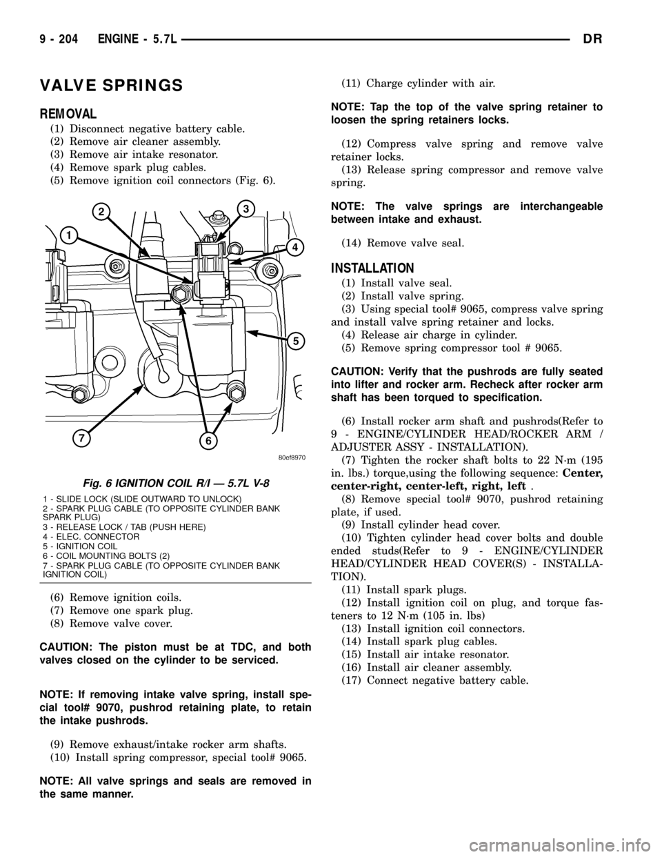
(5) Remove ignition coil connectors (Fig. 6).
(6) Remove ignition coils.
(7) Remove one spark plug.
(8) Remove valve cover.
CAUTION: The piston must be at TDC, and both
valves closed on the cylinder to be serviced.
NOTE: If removing intake valve spring, install spe-
cial tool# 9070, pushrod retaining plate, to retain
the intake pushrods.
(9) Remove exhaust/intake rocker arm shafts.
(10) Install spring compressor, special tool# 9065.
NOTE: All valve springs and seals are removed in
the same manner.(11) Charge cylinder with air.
NOTE: Tap the top of the valve spring retainer to
loosen the spring retainers locks.
(12) Compress valve spring and remove valve
retainer locks.
(13) Release spring compressor and remove valve
spring.
NOTE: The valve springs are interchangeable
between intake and exhaust.
(14) Remove valve seal.
INSTALLATION
(1) Install valve seal.
(2) Install valve spring.
(3) Using special tool# 9065, compress valve spring
and install valve spring retainer and locks.
(4) Release air charge in cylinder.
(5) Remove spring compressor tool # 9065.
CAUTION: Verify that the pushrods are fully seated
into lifter and rocker arm. Recheck after rocker arm
shaft has been torqued to specification.
(6) Install rocker arm shaft and pushrods(Refer to
9 - ENGINE/CYLINDER HEAD/ROCKER ARM /
ADJUSTER ASSY - INSTALLATION).
(7) Tighten the rocker shaft bolts to 22 N´m (195
in. lbs.) torque,using the following sequence:Center,
center-right, center-left, right, left.
(8) Remove special tool# 9070, pushrod retaining
plate, if used.
(9) Install cylinder head cover.
(10) Tighten cylinder head cover bolts and double
ended studs(Refer to 9 - ENGINE/CYLINDER
HEAD/CYLINDER HEAD COVER(S) - INSTALLA-
TION).
(11) Install spark plugs.
(12) Install ignition coil on plug, and torque fas-
teners to 12 N´m (105 in. lbs)
(13) Install ignition coil connectors.
(14) Install spark plug cables.
(15) Install air intake resonator.
(16) Install air cleaner assembly.
(17) Connect negative battery cable.
Fig. 6 IGNITION COIL R/I Ð 5.7L V-8
1 - SLIDE LOCK (SLIDE OUTWARD TO UNLOCK)
2 - SPARK PLUG CABLE (TO OPPOSITE CYLINDER BANK
SPARK PLUG)
3 - RELEASE LOCK / TAB (PUSH HERE)
4 - ELEC. CONNECTOR
5 - IGNITION COIL
6 - COIL MOUNTING BOLTS (2)
7 - SPARK PLUG CABLE (TO OPPOSITE CYLINDER BANK
IGNITION COIL)
9 - 204 ENGINE - 5.7LDR
Page 1463 of 2627
material to cure. This material is available in three
ounce tubes and has a shelf life of one year. After one
year this material will not properly cure. Always
inspect the package for the expiration date before
use.
MOPARtATF RTV
MopartATF RTV is a specifically designed black
silicone rubber RTV that retains adhesion and seal-
ing properties to seal components exposed to auto-
matic transmission fluid, engine coolants, and
moisture. This material is available in three ounce
tubes and has a shelf life of one year. After one year
this material will not properly cure. Always inspect
the package for the expiration date before use.
MOPARtGASKET MAKER
MopartGasket Maker is an anaerobic type gasket
material. The material cures in the absence of air
when squeezed between two metallic surfaces. It will
not cure if left in the uncovered tube. The anaerobic
material is for use between two machined surfaces.
Do not use on flexible metal flanges.
MOPARtGASKET SEALANT
MopartGasket Sealant is a slow drying, perma-
nently soft sealer. This material is recommended for
sealing threaded fittings and gaskets against leakage
of oil and coolant. Can be used on threaded and
machined parts under all temperatures. This mate-
rial is used on engines with multi-layer steel (MLS)
cylinder head gaskets. This material also will pre-
vent corrosion. MopartGasket Sealant is available in
a 13 oz. aerosol can or 4oz./16 oz. can w/applicator.
FORM-IN-PLACE GASKET AND SEALER
APPLICATION
Assembling parts using a form-in-place gasket
requires care but it's easier than using precut gas-
kets.
MopartGasket Maker material should be applied
sparingly 1 mm (0.040 in.) diameter or less of sealant
to one gasket surface. Be certain the material sur-
rounds each mounting hole. Excess material can eas-
ily be wiped off. Components should be torqued in
place within 15 minutes. The use of a locating dowel
is recommended during assembly to prevent smear-
ing material off the location.
MopartEngine RTV GEN II or ATF RTV gasket
material should be applied in a continuous bead
approximately 3 mm (0.120 in.) in diameter. All
mounting holes must be circled. For corner sealing, a
3.17 or 6.35 mm (1/8 or 1/4 in.) drop is placed in the
center of the gasket contact area. Uncured sealant
may be removed with a shop towel. Components
should be torqued in place while the sealant is still
wet to the touch (within 10 minutes). The usage of a
locating dowel is recommended during assembly to
prevent smearing material off the location.MopartGasket Sealant in an aerosol can should be
applied using a thin, even coat sprayed completely
over both surfaces to be joined, and both sides of a
gasket. Then proceed with assembly. Material in a
can w/applicator can be brushed on evenly over the
sealing surfaces. Material in an aerosol can should be
used on engines with multi-layer steel gaskets.
STANDARD PROCEDURE - REPAIR DAMAGED
OR WORN THREADS
CAUTION: Be sure that the tapped holes maintain
the original center line.
Damaged or worn threads can be repaired. Essen-
tially, this repair consists of:
²Drilling out worn or damaged threads.
²Tapping the hole with a special Heli-Coil Tap, or
equivalent.
²Installing an insert into the tapped hole to bring
the hole back to its original thread size.
STANDARD PROCEDUREÐHYDROSTATIC
LOCK
CAUTION: DO NOT use the starter motor to rotate
the crankshaft. Severe damage could occur.
When an engine is suspected of hydrostatic lock
(regardless of what caused the problem), follow the
steps below.
(1) Disconnect the negative cable(s) from the bat-
tery.
(2) Inspect air cleaner, induction system, and
intake manifold to ensure system is dry and clear of
foreign material.
(3) Place a shop towel around the fuel injectors to
catch any fluid that may possibly be under pressure
in the cylinder head. Remove the fuel injectors (Refer
to 14 - FUEL SYSTEM/FUEL INJECTION/FUEL
INJECTOR - REMOVAL).
(4) With all injectors removed, rotate the crank-
shaft using the crankshaft barring tool (PN 7471±B).
(5) Identify the fluid in the cylinders (coolant, fuel,
oil, etc.).
(6) Be sure all fluid has been removed from the
cylinders.
(7) Repair engine or components as necessary to
prevent this problem from occurring again.
(8) Squirt a small amount of engine oil into the
cylinders to lubricate the walls. This will prevent
damage on restart.
(9) Install fuel injectors (Refer to 14 - FUEL SYS-
TEM/FUEL INJECTION/FUEL INJECTOR -
INSTALLATION).
9 - 240 ENGINE 5.9L DIESELDR
ENGINE 5.9L DIESEL (Continued)
Page 1582 of 2627
REMOVAL
3.7L V-6
WARNING: THE FUEL SYSTEM IS UNDER CON-
STANT PRESSURE EVEN WITH ENGINE OFF.
BEFORE SERVICING FUEL RAIL, FUEL SYSTEM
PRESSURE MUST BE RELEASED.
CAUTION: The left and right fuel rails are replaced
as an assembly. Do not attempt to separate rail
halves at connector tubes (Fig. 18). Due to design
of tubes, it does not use any clamps. Never attempt
to install a clamping device of any kind to tubes.
When removing fuel rail assembly for any reason,
be careful not to bend or kink tubes.
(1) Remove fuel tank filler tube cap.
(2) Perform Fuel System Pressure Release Proce-
dure.
(3) Remove negative battery cable at battery.
(4) Remove air duct at throttle body air box.
(5) Remove air box at throttle body.
(6) Remove air resonator mounting bracket at
front of throttle body (2 bolts).
(7) Disconnect fuel line latch clip and fuel line at
fuel rail. A special tool will be necessary for fuel line
disconnection. Refer to Quick-Connect Fittings.
(8) Remove necessary vacuum lines at throttle
body.
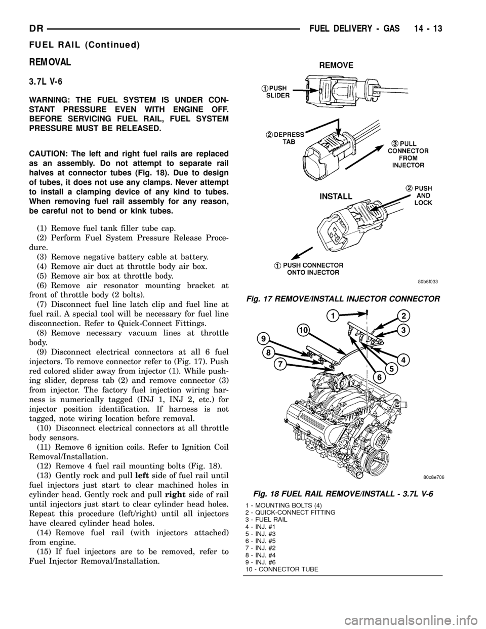
(9) Disconnect electrical connectors at all 6 fuel
injectors. To remove connector refer to (Fig. 17). Push
red colored slider away from injector (1). While push-
ing slider, depress tab (2) and remove connector (3)
from injector. The factory fuel injection wiring har-
ness is numerically tagged (INJ 1, INJ 2, etc.) for
injector position identification. If harness is not
tagged, note wiring location before removal.
(10) Disconnect electrical connectors at all throttle
body sensors.
(11) Remove 6 ignition coils. Refer to Ignition Coil
Removal/Installation.
(12) Remove 4 fuel rail mounting bolts (Fig. 18).
(13) Gently rock and pullleftside of fuel rail until
fuel injectors just start to clear machined holes in
cylinder head. Gently rock and pullrightside of rail
until injectors just start to clear cylinder head holes.
Repeat this procedure (left/right) until all injectors
have cleared cylinder head holes.
(14) Remove fuel rail (with injectors attached)
from engine.
(15) If fuel injectors are to be removed, refer to
Fuel Injector Removal/Installation.
Fig. 17 REMOVE/INSTALL INJECTOR CONNECTOR
Fig. 18 FUEL RAIL REMOVE/INSTALL - 3.7L V-6
1 - MOUNTING BOLTS (4)
2 - QUICK-CONNECT FITTING
3 - FUEL RAIL
4 - INJ. #1
5 - INJ. #3
6 - INJ. #5
7 - INJ. #2
8 - INJ. #4
9 - INJ. #6
10 - CONNECTOR TUBE
DRFUEL DELIVERY - GAS 14 - 13
FUEL RAIL (Continued)