check engine DODGE RAM 1500 1998 2.G Workshop Manual
[x] Cancel search | Manufacturer: DODGE, Model Year: 1998, Model line: RAM 1500, Model: DODGE RAM 1500 1998 2.GPages: 2627
Page 690 of 2627
VACUUM RESERVOIR
DESCRIPTION
The vacuum reservoir is a plastic storage tank con-
nected to an engine vacuum source by vacuum lines.
A vacuum reservoir is not used with diesel engines or
the 5.7L gas powered engine.
OPERATION
The vacuum reservoir is used to supply the vac-
uum needed to maintain proper speed control opera-
tion when engine vacuum drops, such as in climbing
a grade while driving. A one-way check valve is used
in the vacuum line between the reservoir and the
vacuum source. This check valve is used to trap
engine vacuum in the reservoir. On certain vehicle
applications, this reservoir is shared with the heat-
ing/air-conditioning system. The vacuum reservoir
cannot be repaired and must be replaced if faulty.
DIAGNOSIS AND TESTING - VACUUM
RESERVOIR
(1) Disconnect vacuum hose at speed control servo
and install a vacuum gauge into the disconnected
hose.
(2) Start engine and observe gauge at idle. Vac-
uum gauge should read at least ten inches of mer-
cury.
(3) If vacuum is less than ten inches of mercury,
determine source of leak. Check vacuum line to
engine for leaks. Also check actual engine intake
manifold vacuum. If manifold vacuum does not meet
this requirement, check for poor engine performance
and repair as necessary.
(4) If vacuum line to engine is not leaking, check
for leak at vacuum reservoir. To locate and gain
access to reservoir, refer to Vacuum Reservoir Remov-
al/Installation in this group. Disconnect vacuum line
at reservoir and connect a hand-operated vacuum
pump to reservoir fitting. Apply vacuum. Reservoir
vacuum should not bleed off. If vacuum is being lost,
replace reservoir.
(5) Verify operation of one-way check valve and
check it for leaks.Certain models may be
equipped with 2 check-valves.
(a) Locate one-way check valve. The valve is
located in vacuum line between vacuum reservoir
and engine vacuum source. Disconnect vacuum
hoses (lines) at each end of valve.(b) Connect a hand-operated vacuum pump to
reservoir end of check valve. Apply vacuum. Vac-
uum should not bleed off. If vacuum is being lost,
replace one-way check valve.
(c) Connect a hand-operated vacuum pump to
vacuum source end of check valve. Apply vacuum.
Vacuum should flow through valve. If vacuum is
not flowing, replace one-way check valve. Seal the
fitting at opposite end of valve with a finger and
apply vacuum. If vacuum will not hold, diaphragm
within check valve has ruptured. Replace valve.
REMOVAL
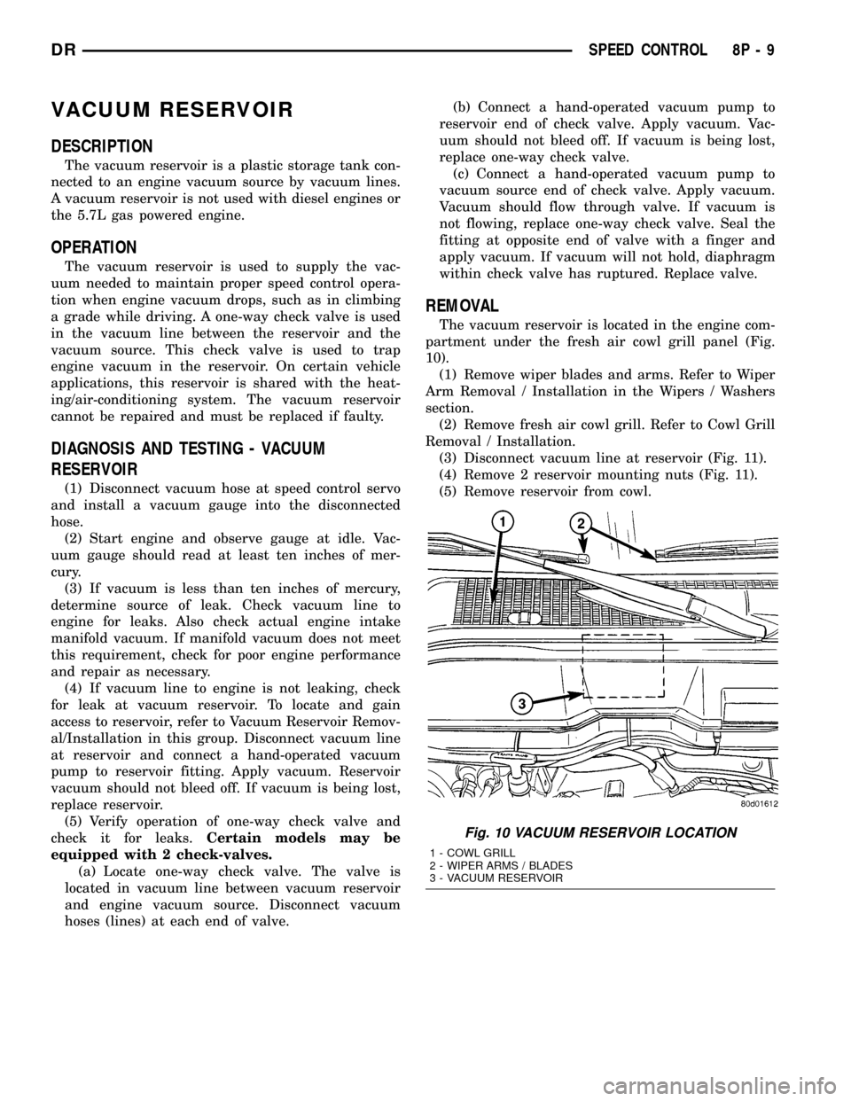
The vacuum reservoir is located in the engine com-
partment under the fresh air cowl grill panel (Fig.
10).
(1) Remove wiper blades and arms. Refer to Wiper
Arm Removal / Installation in the Wipers / Washers
section.
(2) Remove fresh air cowl grill. Refer to Cowl Grill
Removal / Installation.
(3) Disconnect vacuum line at reservoir (Fig. 11).
(4) Remove 2 reservoir mounting nuts (Fig. 11).
(5) Remove reservoir from cowl.
Fig. 10 VACUUM RESERVOIR LOCATION
1 - COWL GRILL
2 - WIPER ARMS / BLADES
3 - VACUUM RESERVOIR
DRSPEED CONTROL 8P - 9
Page 698 of 2627
WIPERS/WASHERS
TABLE OF CONTENTS
page page
WIPERS/WASHERS
DESCRIPTION..........................1
OPERATION............................4
DIAGNOSIS AND TESTING - WIPER &
WASHER SYSTEM.....................6
CLEANING - WIPER & WASHER SYSTEM.....6
INSPECTION - WIPER & WASHER SYSTEM . . . 7
CHECK VALVE
DESCRIPTION..........................7
OPERATION............................8
REMOVAL.............................8
INSTALLATION..........................8
WASHER FLUID LEVEL SWITCH
DESCRIPTION..........................9
OPERATION............................9
REMOVAL.............................10
INSTALLATION.........................11
WASHER HOSES/TUBES
DESCRIPTION.........................11
OPERATION...........................11
WASHER NOZZLE
DESCRIPTION.........................11
OPERATION...........................12
REMOVAL.............................12
INSTALLATION.........................12
WASHER PUMP/MOTOR
DESCRIPTION.........................13
OPERATION...........................13
REMOVAL.............................14
INSTALLATION.........................14
WASHER RESERVOIR
DESCRIPTION.........................14
OPERATION...........................15
REMOVAL
REMOVAL - EXCEPT DIESEL ENGINE.....15REMOVAL - DIESEL ENGINE............16
INSTALLATION
INSTALLATION - EXCEPT DIESEL ENGINE . . 17
INSTALLATION - DIESEL ENGINE.........17
WIPER ARM
DESCRIPTION.........................17
OPERATION...........................18
REMOVAL.............................18
INSTALLATION.........................18
WIPER BLADE
DESCRIPTION.........................18
OPERATION...........................19
REMOVAL.............................19
INSTALLATION.........................20
WIPER HIGH/LOW RELAY
DESCRIPTION.........................20
OPERATION...........................20
DIAGNOSIS AND TESTING - WIPER HIGH/
LOW RELAY.........................21
REMOVAL.............................21
INSTALLATION.........................22
WIPER MODULE
DESCRIPTION.........................22
OPERATION...........................23
REMOVAL.............................23
INSTALLATION.........................23
WIPER ON/OFF RELAY
DESCRIPTION.........................24
OPERATION...........................25
DIAGNOSIS AND TESTING - WIPER ON/OFF
RELAY..............................25
REMOVAL.............................26
INSTALLATION.........................26
WIPERS/WASHERS
DESCRIPTION
An electrically operated intermittent wiper and
washer system is standard factory-installed safety
equipment on this model (Fig. 1). The wiper and
washer system includes the following major compo-
nents, which are described in further detail else-
where in this service information:
²Check Valve- The washer system check valve
is integral to the wye fitting located in the washer
plumbing between the cowl plenum washer hose andthe washer nozzles, and is concealed beneath the
cowl plenum cover/grille panel at the base of the
windshield.
²Front Control Module- The Front Control
Module (FCM) is integral to the Integrated Power
Module (IPM). The IPM is located in the engine com-
partment, near the battery. (Refer to 8 - ELECTRI-
CAL/POWER DISTRIBUTION/INTEGRATED
POWER MODULE - DESCRIPTION).
²Instrument Cluster- In this model, the instru-
ment cluster is also sometimes referred to as the Cab
Control Node (CCN). The instrument cluster is
located in the instrument panel above the steering
DRWIPERS/WASHERS 8R - 1
Page 705 of 2627
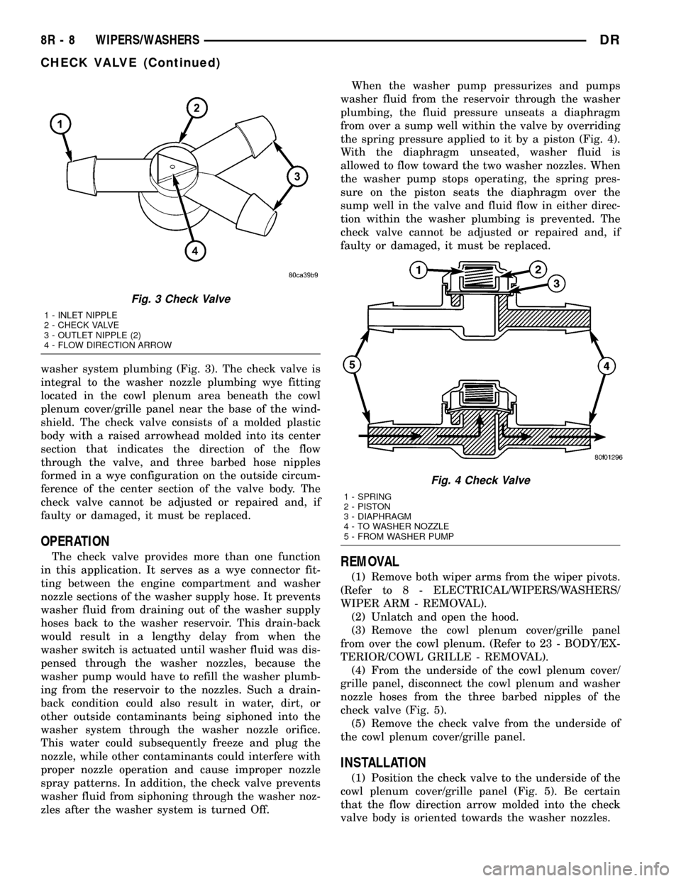
washer system plumbing (Fig. 3). The check valve is
integral to the washer nozzle plumbing wye fitting
located in the cowl plenum area beneath the cowl
plenum cover/grille panel near the base of the wind-
shield. The check valve consists of a molded plastic
body with a raised arrowhead molded into its center
section that indicates the direction of the flow
through the valve, and three barbed hose nipples
formed in a wye configuration on the outside circum-
ference of the center section of the valve body. The
check valve cannot be adjusted or repaired and, if
faulty or damaged, it must be replaced.
OPERATION
The check valve provides more than one function
in this application. It serves as a wye connector fit-
ting between the engine compartment and washer
nozzle sections of the washer supply hose. It prevents
washer fluid from draining out of the washer supply
hoses back to the washer reservoir. This drain-back
would result in a lengthy delay from when the
washer switch is actuated until washer fluid was dis-
pensed through the washer nozzles, because the
washer pump would have to refill the washer plumb-
ing from the reservoir to the nozzles. Such a drain-
back condition could also result in water, dirt, or
other outside contaminants being siphoned into the
washer system through the washer nozzle orifice.
This water could subsequently freeze and plug the
nozzle, while other contaminants could interfere with
proper nozzle operation and cause improper nozzle
spray patterns. In addition, the check valve prevents
washer fluid from siphoning through the washer noz-
zles after the washer system is turned Off.When the washer pump pressurizes and pumps
washer fluid from the reservoir through the washer
plumbing, the fluid pressure unseats a diaphragm
from over a sump well within the valve by overriding
the spring pressure applied to it by a piston (Fig. 4).
With the diaphragm unseated, washer fluid is
allowed to flow toward the two washer nozzles. When
the washer pump stops operating, the spring pres-
sure on the piston seats the diaphragm over the
sump well in the valve and fluid flow in either direc-
tion within the washer plumbing is prevented. The
check valve cannot be adjusted or repaired and, if
faulty or damaged, it must be replaced.REMOVAL
(1) Remove both wiper arms from the wiper pivots.
(Refer to 8 - ELECTRICAL/WIPERS/WASHERS/
WIPER ARM - REMOVAL).
(2) Unlatch and open the hood.
(3) Remove the cowl plenum cover/grille panel
from over the cowl plenum. (Refer to 23 - BODY/EX-
TERIOR/COWL GRILLE - REMOVAL).
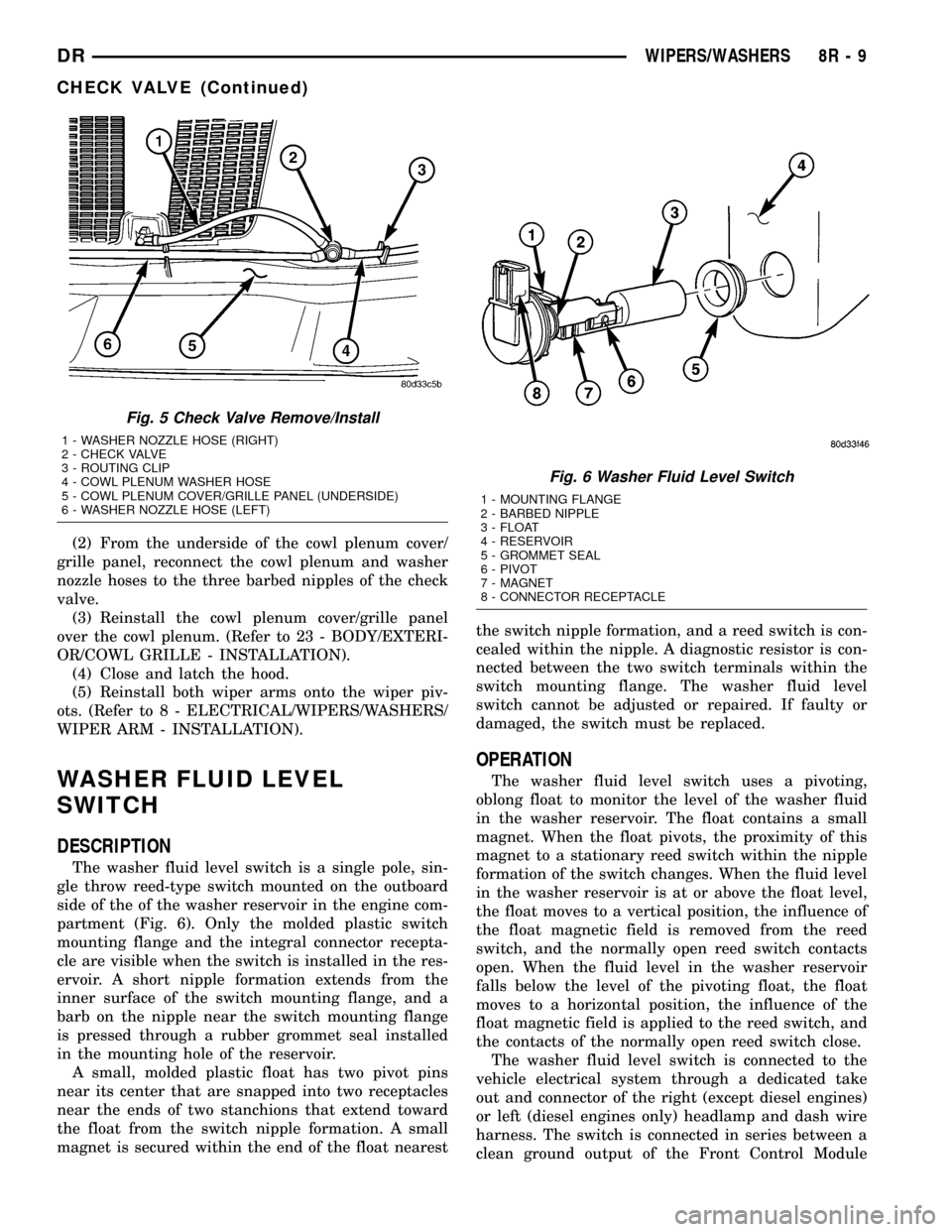
(4) From the underside of the cowl plenum cover/
grille panel, disconnect the cowl plenum and washer
nozzle hoses from the three barbed nipples of the
check valve (Fig. 5).
(5) Remove the check valve from the underside of
the cowl plenum cover/grille panel.
INSTALLATION
(1) Position the check valve to the underside of the
cowl plenum cover/grille panel (Fig. 5). Be certain
that the flow direction arrow molded into the check
valve body is oriented towards the washer nozzles.
Fig. 3 Check Valve
1 - INLET NIPPLE
2 - CHECK VALVE
3 - OUTLET NIPPLE (2)
4 - FLOW DIRECTION ARROW
Fig. 4 Check Valve
1 - SPRING
2 - PISTON
3 - DIAPHRAGM
4 - TO WASHER NOZZLE
5 - FROM WASHER PUMP
8R - 8 WIPERS/WASHERSDR
CHECK VALVE (Continued)
Page 706 of 2627
(2) From the underside of the cowl plenum cover/
grille panel, reconnect the cowl plenum and washer
nozzle hoses to the three barbed nipples of the check
valve.
(3) Reinstall the cowl plenum cover/grille panel
over the cowl plenum. (Refer to 23 - BODY/EXTERI-
OR/COWL GRILLE - INSTALLATION).
(4) Close and latch the hood.
(5) Reinstall both wiper arms onto the wiper piv-
ots. (Refer to 8 - ELECTRICAL/WIPERS/WASHERS/
WIPER ARM - INSTALLATION).
WASHER FLUID LEVEL
SWITCH
DESCRIPTION
The washer fluid level switch is a single pole, sin-
gle throw reed-type switch mounted on the outboard
side of the of the washer reservoir in the engine com-
partment (Fig. 6). Only the molded plastic switch
mounting flange and the integral connector recepta-
cle are visible when the switch is installed in the res-
ervoir. A short nipple formation extends from the
inner surface of the switch mounting flange, and a
barb on the nipple near the switch mounting flange
is pressed through a rubber grommet seal installed
in the mounting hole of the reservoir.
A small, molded plastic float has two pivot pins
near its center that are snapped into two receptacles
near the ends of two stanchions that extend toward
the float from the switch nipple formation. A small
magnet is secured within the end of the float nearestthe switch nipple formation, and a reed switch is con-
cealed within the nipple. A diagnostic resistor is con-
nected between the two switch terminals within the
switch mounting flange. The washer fluid level
switch cannot be adjusted or repaired. If faulty or
damaged, the switch must be replaced.
OPERATION
The washer fluid level switch uses a pivoting,
oblong float to monitor the level of the washer fluid
in the washer reservoir. The float contains a small
magnet. When the float pivots, the proximity of this
magnet to a stationary reed switch within the nipple
formation of the switch changes. When the fluid level
in the washer reservoir is at or above the float level,
the float moves to a vertical position, the influence of
the float magnetic field is removed from the reed
switch, and the normally open reed switch contacts
open. When the fluid level in the washer reservoir
falls below the level of the pivoting float, the float
moves to a horizontal position, the influence of the
float magnetic field is applied to the reed switch, and
the contacts of the normally open reed switch close.
The washer fluid level switch is connected to the
vehicle electrical system through a dedicated take
out and connector of the right (except diesel engines)
or left (diesel engines only) headlamp and dash wire
harness. The switch is connected in series between a
clean ground output of the Front Control Module
Fig. 5 Check Valve Remove/Install
1 - WASHER NOZZLE HOSE (RIGHT)
2 - CHECK VALVE
3 - ROUTING CLIP
4 - COWL PLENUM WASHER HOSE
5 - COWL PLENUM COVER/GRILLE PANEL (UNDERSIDE)
6 - WASHER NOZZLE HOSE (LEFT)
Fig. 6 Washer Fluid Level Switch
1 - MOUNTING FLANGE
2 - BARBED NIPPLE
3 - FLOAT
4 - RESERVOIR
5 - GROMMET SEAL
6 - PIVOT
7 - MAGNET
8 - CONNECTOR RECEPTACLE
DRWIPERS/WASHERS 8R - 9
CHECK VALVE (Continued)
Page 708 of 2627
INSTALLATION
(1) Install a new rubber grommet seal into the
washer fluid level switch mounting hole in the
washer reservoir. Always use a new rubber grommet
seal on the reservoir.
(2) Insert the float of the washer fluid level switch
through the rubber grommet seal and into the
washer reservoir. The connector receptacle of the
washer fluid level switch should be pointed upward.
(3) Using hand pressure, press firmly and evenly
on the washer fluid level switch mounting flange
until the barbed nipple is fully seated in the rubber
grommet seal in the washer reservoir mounting hole.
(4) Reconnect the right (except diesel engine) or
left (diesel engine only) headlamp and dash wire har-
ness connector for the washer fluid level switch to
the switch connector receptacle (Fig. 7) or (Fig. 8).
(5) Reconnect the removed washer hose to the
barbed outlet nipple of the washer pump/motor unit.
(6) Refill the washer reservoir with the washer
fluid drained from the reservoir during the removal
procedure.
(7) Reconnect the battery negative cable.
(8) Close and latch the hood.
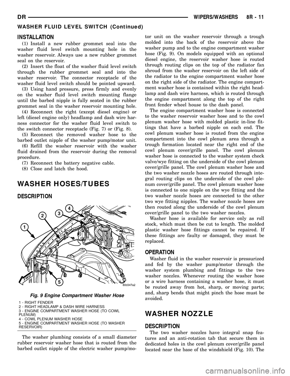
WASHER HOSES/TUBES
DESCRIPTION
The washer plumbing consists of a small diameter
rubber reservoir washer hose that is routed from the
barbed outlet nipple of the electric washer pump/mo-tor unit on the washer reservoir through a trough
molded into the back of the reservoir above the
washer pump and to the engine compartment washer
hose (Fig. 9). On models equipped with an optional
diesel engine, the reservoir washer hose is routed
through routing clips on the top of the radiator fan
shroud from the washer reservoir on the left side of
the radiator to the engine compartment washer hose
on the right side of the radiator. The engine compart-
ment washer hose is contained within the right head-
lamp and dash wire harness, which is routed through
the engine compartment along the top of the right
front fender wheel house to the dash panel.
The engine compartment washer hose is connected
to the washer reservoir washer hose and to the cowl
plenum washer hose with molded plastic in-line fit-
tings that have a barbed nipple on each end. The
cowl plenum washer hose is routed from the engine
compartment into the cowl plenum area through a
trough formation located near the right end of the
cowl plenum cover/grille panel. The cowl plenum
washer hose is connected to the washer system check
valve/wye fitting on the underside of the cowl plenum
cover/grille panel. The cowl plenum washer hose and
the two washer nozzle hoses are routed through inte-
gral routing clips on the underside of the cowl ple-
num cover/grille panel. The cowl plenum washer hose
is connected to one nipple on the wye fitting and the
two washer nozzle hoses are connected to the other
two wye fitting nipples. The washer nozzle hoses are
then routed along the underside of the cowl plenum
cover/grille panel to the two washer nozzles.
Washer hose is available for service only as roll
stock, which must then be cut to length. The molded
plastic washer hose fittings cannot be repaired. If
these fittings are faulty or damaged, they must be
replaced.
OPERATION
Washer fluid in the washer reservoir is pressurized
and fed by the washer pump/motor through the
washer system plumbing and fittings to the two
washer nozzles. Whenever routing the washer hose
or a wire harness containing a washer hose, it must
be routed away from hot, sharp, or moving parts;
and, sharp bends that might pinch the hose must be
avoided.
WASHER NOZZLE
DESCRIPTION
The two washer nozzles have integral snap fea-
tures and an anti-rotation tab that secure them in
dedicated holes in the cowl plenum cover/grille panel
located near the base of the windshield (Fig. 10). The
Fig. 9 Engine Compartment Washer Hose
1 - RIGHT FENDER
2 - RIGHT HEADLAMP & DASH WIRE HARNESS
3 - ENGINE COMPARTMENT WASHER HOSE (TO COWL
PLENUM)
4 - COWL PLENUM WASHER HOSE
5 - ENGINE COMPARTMENT WASHER HOSE (TO WASHER
RESERVOIR)
DRWIPERS/WASHERS 8R - 11
WASHER FLUID LEVEL SWITCH (Continued)
Page 734 of 2627
DESCRIPTION - CONNECTOR, GROUND AND
SPLICE INFORMATION
CAUTION: Not all connectors are serviced. Some
connectors are serviced only with a harness. A typ-
ical example might be the Supplemental Restraint
System connectors. Always check parts availability
before attempting a repair.
IDENTIFICATION
In-line connectors are identified by a number, as
follows:
²In-line connectors located in the engine compart-
ment are C100 series numbers
²In-line connectors located in the Instrument
Panel area are C200 series numbers.
²In-line connectors located in the body are C300
series numbers.
²Jumper harness connectors are C400 series
numbers.
²Grounds and ground connectors are identified
with a ªGº and follow the same series numbering as
the in-line connectors.
²Splices are identified with an ªSº and follow the
same series numbering as the in-line connectors.
²Component connectors are identified by the com-
ponent name instead of a number. Multiple connec-
tors on a component use a C1, C2, etc. identifier.
LOCATIONS
Section 8W-91 contains connector/ground/splice
location illustrations. The illustrations contain the
connector name (or number)/ground number/splice
number and component identification. Connector/
ground/splice location charts in section 8W-91 refer-
ence the figure numbers of the illustrations.
The abbreviation T/O is used in the component
location section to indicate a point in which the wir-
ing harness branches out to a component. The abbre-
viation N/S means Not Shown in the illustrations
WARNING
WARNINGS - GENERAL
WARNINGSprovide information to prevent per-
sonal injury and vehicle damage. Below is a list of
general warnings that should be followed any time a
vehicle is being serviced.
WARNING: ALWAYS WEAR SAFETY GLASSES FOR
EYE PROTECTION.
WARNING: USE SAFETY STANDS ANYTIME A PRO-
CEDURE REQUIRES BEING UNDER A VEHICLE.WARNING: BE SURE THAT THE IGNITION SWITCH
ALWAYS IS IN THE OFF POSITION, UNLESS THE
PROCEDURE REQUIRES IT TO BE ON.
WARNING: SET THE PARKING BRAKE WHEN
WORKING ON ANY VEHICLE. AN AUTOMATIC
TRANSMISSION SHOULD BE IN PARK. A MANUAL
TRANSMISSION SHOULD BE IN NEUTRAL.
WARNING: OPERATE THE ENGINE ONLY IN A
WELL-VENTILATED AREA.
WARNING: KEEP AWAY FROM MOVING PARTS
WHEN THE ENGINE IS RUNNING, ESPECIALLY THE
FAN AND BELTS.
WARNING: TO PREVENT SERIOUS BURNS, AVOID
CONTACT WITH HOT PARTS SUCH AS THE RADIA-
TOR, EXHAUST MANIFOLD(S), TAIL PIPE, CATA-
LYTIC CONVERTER AND MUFFLER.
WARNING: DO NOT ALLOW FLAME OR SPARKS
NEAR THE BATTERY. GASES ARE ALWAYS
PRESENT IN AND AROUND THE BATTERY.
WARNING: ALWAYS REMOVE RINGS, WATCHES,
LOOSE HANGING JEWELRY AND AVOID LOOSE
CLOTHING.
DIAGNOSIS AND TESTING - WIRING HARNESS
TROUBLESHOOTING TOOLS
When diagnosing a problem in an electrical circuit
there are several common tools necessary. These tools
are listed and explained below.
²Jumper Wire - This is a test wire used to con-
nect two points of a circuit. It can be used to bypass
an open in a circuit.
WARNING: NEVER USE A JUMPER WIRE ACROSS
A LOAD, SUCH AS A MOTOR, CONNECTED
BETWEEN A BATTERY FEED AND GROUND.
²Voltmeter - Used to check for voltage on a cir-
cuit. Always connect the black lead to a known good
ground and the red lead to the positive side of the
circuit.
CAUTION: Most of the electrical components used
in today's vehicles are Solid State. When checking
voltages in these circuits, use a meter with a 10 -
megohm or greater impedance rating.
DR8W-01 WIRING DIAGRAM INFORMATION 8W - 01 - 7
WIRING DIAGRAM INFORMATION (Continued)
Page 1220 of 2627
(3) Connect the electrical connectors by pushing
straight on and rotating the connector arm inboard,
until the connector is firmly locked in place on the
module assembly.
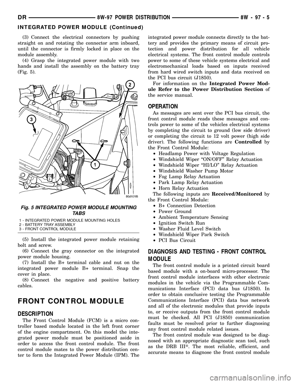
(4) Grasp the integrated power module with two
hands and install the assembly on the battery tray
(Fig. 5).
(5) Install the integrated power module retaining
bolt and screw.
(6) Connect the gray connector on the integrated
power module housing.
(7) Install the B+ terminal cable and nut on the
integrated power module B+ terminal. Snap the
cover in place.
(8) Connect the negative and positive battery
cables.
FRONT CONTROL MODULE
DESCRIPTION
The Front Control Module (FCM) is a micro con-
troller based module located in the left front corner
of the engine compartment. On this model the inte-
grated power module must be positioned aside in
order to access the front control module. The front
control module mates to the power distribution cen-
ter to form the Integrated Power Module (IPM). Theintegrated power module connects directly to the bat-
tery and provides the primary means of circuit pro-
tection and power distribution for all vehicle
electrical systems. The front control module controls
power to some of these vehicle systems electrical and
electromechanical loads based on inputs received
from hard wired switch inputs and data received on
the PCI bus circuit (J1850).
For information on theIntegrated Power Mod-
ule Refer to the Power Distribution Sectionof
the service manual.
OPERATION
As messages are sent over the PCI bus circuit, the
front control module reads these messages and con-
trols power to some of the vehicles electrical systems
by completing the circuit to ground (low side driver)
or completing the circuit to 12 volt power (high side
driver). The following functions areControlledby
the Front Control Module:
²Headlamp Power with Voltage Regulation
²Windshield Wiper ªON/OFFº Relay Actuation
²Windshield Wiper ªHI/LOº Relay Actuation
²Windshield Washer Pump Motor
²Fog Lamp Relay Actuation
²Park Lamp Relay Actuation
²Horn Relay Actuation
The following inputs areReceived/Monitoredby
the Front Control Module:
²B+ Connection Detection
²Power Ground
²Ambient Temperature Sensing
²Ignition Switch Run
²Washer Fluid Level Switch
²Windshield Wiper Park Switch
²PCI Bus Circuit
DIAGNOSIS AND TESTING - FRONT CONTROL
MODULE
The front control module is a printed circuit board
based module with a on-board micro-processor. The
front control module interfaces with other electronic
modules in the vehicle via the Programmable Com-
munications Interface (PCI) data bus (J1850). In
order to obtain conclusive testing the Programmable
Communications Interface (PCI) data bus network
and all of the electronic modules that provide inputs
to, or receive outputs from the front control module
must be checked. All PCI (J1850) communication
faults must be resolved prior to further diagnosing
any front control module related issues.
The front control module was designed to be diag-
nosed with an appropriate diagnostic scan tool, such
as the DRB IIIt. The most reliable, efficient, and
accurate means to diagnose the front control module
Fig. 5 INTEGRATED POWER MODULE MOUNTING
TABS
1 - INTEGRATED POWER MODULE MOUNTING HOLES
2 - BATTERY TRAY ASSEMBLY
3 - FRONT CONTROL MODULE
DR8W-97 POWER DISTRIBUTION 8W - 97 - 5
INTEGRATED POWER MODULE (Continued)
Page 1225 of 2627
REMOVAL.............................38
INSTALLATION.........................38
ENGINE BLOCK
DESCRIPTION.........................38
STANDARD PROCEDURE - CYLINDER BORE
HONING............................38
CLEANING............................39
INSPECTION..........................39
CRANKSHAFT
DESCRIPTION.........................40
REMOVAL.............................40
INSPECTION..........................41
INSTALLATION.........................42
CRANKSHAFT MAIN BEARINGS
STANDARD PROCEDURE
MAIN BEARING FITTING................44
CRANKSHAFT OIL SEAL - FRONT
REMOVAL.............................46
INSTALLATION.........................46
CRANKSHAFT OIL SEAL - REAR
REMOVAL.............................47
INSTALLATION.........................47
FLEX PLATE
REMOVAL.............................48
INSTALLATION.........................48
PISTON & CONNECTING ROD
DESCRIPTION.........................48
STANDARD PROCEDURE
CONNECTING ROD BEARING FITTING....49
STANDARD PROCEDURE - PISTON FITTING..51
REMOVAL.............................51
CLEANING............................52
INSPECTION..........................52
INSTALLATION.........................52
PISTON RINGS
STANDARD PROCEDURE - PISTON RING
FITTING.............................53
VIBRATION DAMPER
REMOVAL.............................55
INSTALLATION.........................56
STRUCTURAL COVER
DESCRIPTION.........................57
OPERATION...........................57
REMOVAL.............................57
INSTALLATION.........................57
FRONT MOUNT
REMOVAL.............................58
INSTALLATION.........................59
REAR MOUNT
REMOVAL.............................61
INSTALLATION.........................61
LUBRICATION
DESCRIPTION.........................61
OPERATION...........................61
DIAGNOSIS AND TESTING
DIAGNOSIS AND TESTING - ENGINE OIL
LEAK...............................64DIAGNOSIS AND TESTING - CHECKING
ENGINE OIL PRESSURE................65
DIAGNOSIS AND TESTING - REAR SEAL
AREA LEAKS.........................65
OIL PAN
DESCRIPTION.........................66
REMOVAL.............................66
CLEANING............................66
INSPECTION..........................66
INSTALLATION.........................66
OIL PRESSURE SENSOR/SWITCH
DESCRIPTION.........................67
OPERATION...........................67
REMOVAL.............................67
INSTALLATION.........................67
OIL PUMP
REMOVAL.............................67
DISASSEMBLY.........................68
INSPECTION..........................68
ASSEMBLY............................69
INSTALLATION.........................69
OIL FILTER
REMOVAL.............................70
INSTALLATION.........................70
OIL
STANDARD PROCEDURE - ENGINE OIL
SERVICE............................71
INTAKE MANIFOLD
DESCRIPTION.........................72
DIAGNOSIS AND TESTING - INTAKE
MANIFOLD LEAKS.....................72
REMOVAL.............................73
INSTALLATION.........................73
EXHAUST MANIFOLD
DESCRIPTION.........................74
REMOVAL.............................74
INSTALLATION.........................74
VALVE TIMING
DESCRIPTION.........................76
OPERATION...........................76
STANDARD PROCEDURE
MEASURING TIMING CHAIN WEAR.......77
SERVICE PROCEDURE - TIMING
VERIFICATION........................77
BALANCE SHAFT
REMOVAL.............................80
INSTALLATION.........................80
IDLER SHAFT
REMOVAL.............................81
INSTALLATION.........................81
TIMING BELT / CHAIN COVER(S)
REMOVAL.............................81
INSTALLATION.........................81
TIMING BELT/CHAIN AND SPROCKETS
REMOVAL.............................83
INSPECTION..........................84
INSTALLATION.........................85
9 - 2 ENGINE - 3.7LDR
Page 1229 of 2627
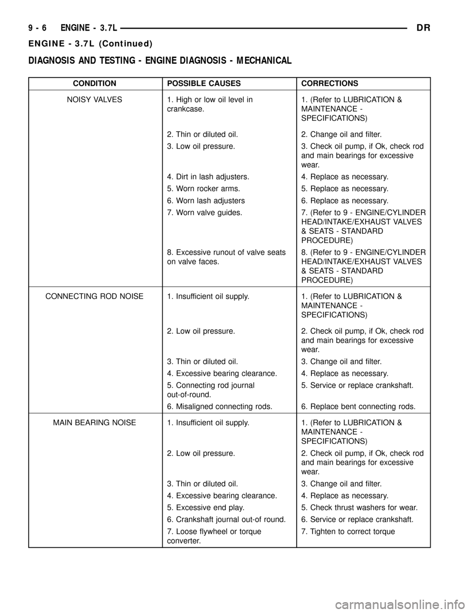
DIAGNOSIS AND TESTING - ENGINE DIAGNOSIS - MECHANICAL
CONDITION POSSIBLE CAUSES CORRECTIONS
NOISY VALVES 1. High or low oil level in
crankcase.1. (Refer to LUBRICATION &
MAINTENANCE -
SPECIFICATIONS)
2. Thin or diluted oil. 2. Change oil and filter.
3. Low oil pressure. 3. Check oil pump, if Ok, check rod
and main bearings for excessive
wear.
4. Dirt in lash adjusters. 4. Replace as necessary.
5. Worn rocker arms. 5. Replace as necessary.
6. Worn lash adjusters 6. Replace as necessary.
7. Worn valve guides. 7. (Refer to 9 - ENGINE/CYLINDER
HEAD/INTAKE/EXHAUST VALVES
& SEATS - STANDARD
PROCEDURE)
8. Excessive runout of valve seats
on valve faces.8. (Refer to 9 - ENGINE/CYLINDER
HEAD/INTAKE/EXHAUST VALVES
& SEATS - STANDARD
PROCEDURE)
CONNECTING ROD NOISE 1. Insufficient oil supply. 1. (Refer to LUBRICATION &
MAINTENANCE -
SPECIFICATIONS)
2. Low oil pressure. 2. Check oil pump, if Ok, check rod
and main bearings for excessive
wear.
3. Thin or diluted oil. 3. Change oil and filter.
4. Excessive bearing clearance. 4. Replace as necessary.
5. Connecting rod journal
out-of-round.5. Service or replace crankshaft.
6. Misaligned connecting rods. 6. Replace bent connecting rods.
MAIN BEARING NOISE 1. Insufficient oil supply. 1. (Refer to LUBRICATION &
MAINTENANCE -
SPECIFICATIONS)
2. Low oil pressure. 2. Check oil pump, if Ok, check rod
and main bearings for excessive
wear.
3. Thin or diluted oil. 3. Change oil and filter.
4. Excessive bearing clearance. 4. Replace as necessary.
5. Excessive end play. 5. Check thrust washers for wear.
6. Crankshaft journal out-of round. 6. Service or replace crankshaft.
7. Loose flywheel or torque
converter.7. Tighten to correct torque
9 - 6 ENGINE - 3.7LDR
ENGINE - 3.7L (Continued)
Page 1230 of 2627
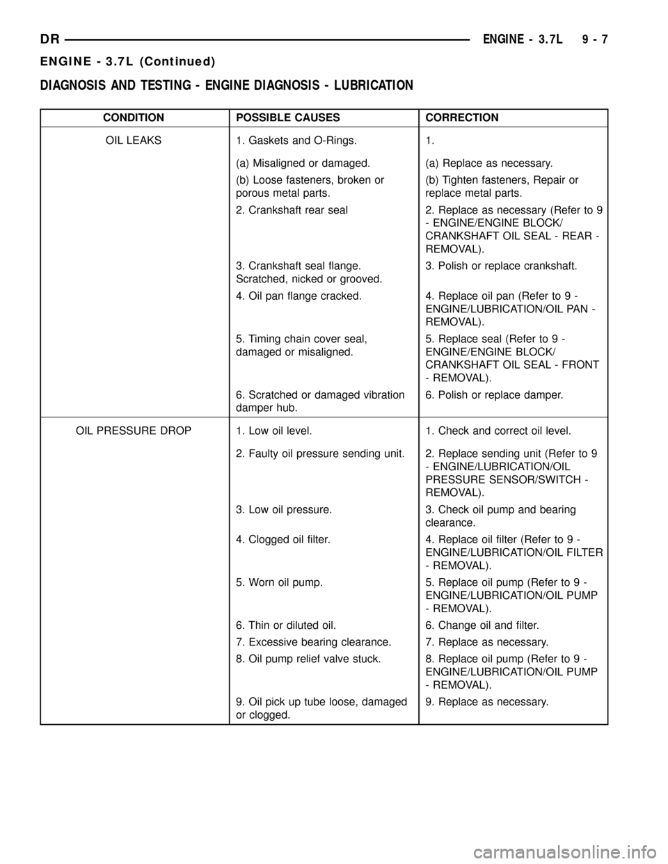
DIAGNOSIS AND TESTING - ENGINE DIAGNOSIS - LUBRICATION
CONDITION POSSIBLE CAUSES CORRECTION
OIL LEAKS 1. Gaskets and O-Rings. 1.
(a) Misaligned or damaged. (a) Replace as necessary.
(b) Loose fasteners, broken or
porous metal parts.(b) Tighten fasteners, Repair or
replace metal parts.
2. Crankshaft rear seal 2. Replace as necessary (Refer to 9
- ENGINE/ENGINE BLOCK/
CRANKSHAFT OIL SEAL - REAR -
REMOVAL).
3. Crankshaft seal flange.
Scratched, nicked or grooved.3. Polish or replace crankshaft.
4. Oil pan flange cracked. 4. Replace oil pan (Refer to 9 -
ENGINE/LUBRICATION/OIL PAN -
REMOVAL).
5. Timing chain cover seal,
damaged or misaligned.5. Replace seal (Refer to 9 -
ENGINE/ENGINE BLOCK/
CRANKSHAFT OIL SEAL - FRONT
- REMOVAL).
6. Scratched or damaged vibration
damper hub.6. Polish or replace damper.
OIL PRESSURE DROP 1. Low oil level. 1. Check and correct oil level.
2. Faulty oil pressure sending unit. 2. Replace sending unit (Refer to 9
- ENGINE/LUBRICATION/OIL
PRESSURE SENSOR/SWITCH -
REMOVAL).
3. Low oil pressure. 3. Check oil pump and bearing
clearance.
4. Clogged oil filter. 4. Replace oil filter (Refer to 9 -
ENGINE/LUBRICATION/OIL FILTER
- REMOVAL).
5. Worn oil pump. 5. Replace oil pump (Refer to 9 -
ENGINE/LUBRICATION/OIL PUMP
- REMOVAL).
6. Thin or diluted oil. 6. Change oil and filter.
7. Excessive bearing clearance. 7. Replace as necessary.
8. Oil pump relief valve stuck. 8. Replace oil pump (Refer to 9 -
ENGINE/LUBRICATION/OIL PUMP
- REMOVAL).
9. Oil pick up tube loose, damaged
or clogged.9. Replace as necessary.
DRENGINE - 3.7L 9 - 7
ENGINE - 3.7L (Continued)