45RFE DODGE RAM 1500 1998 2.G User Guide
[x] Cancel search | Manufacturer: DODGE, Model Year: 1998, Model line: RAM 1500, Model: DODGE RAM 1500 1998 2.GPages: 2627
Page 1120 of 2627
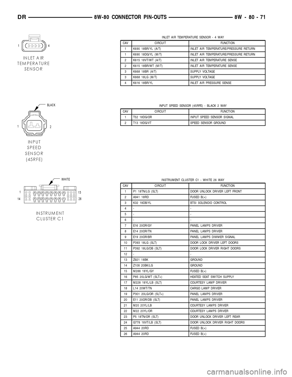
INLET AIR TEMPERATURE SENSOR-4WAY
CAV CIRCUIT FUNCTION
1 K690 18BR/YL (A/T) INLET AIR TEMPERATURE/PRESSURE RETURN
1 K690 18DG/YL (M/T) INLET AIR TEMPERATURE/PRESSURE RETURN
2 K615 18VT/WT (A/T) INLET AIR TEMPERATURE SENSE
2 K615 18BR/WT (M/T) INLET AIR TEMPERATURE SENSE
3 K668 18BR (A/T) SUPPLY VOLTAGE
3 K668 18LG (M/T) SUPPLY VOLTAGE
4 K616 18BR/YL INLET AIR PRESSURE SENSE
INPUT SPEED SENSOR (45RFE) - BLACK 2 WAY
CAV CIRCUIT FUNCTION
1 T52 18DG/OR INPUT SPEED SENSOR SIGNAL
2 T13 18DG/VT SPEED SENSOR GROUND
INSTRUMENT CLUSTER C1 - WHITE 26 WAY
CAV CIRCUIT FUNCTION
1 P1 18TN/LG (SLT) DOOR UNLOCK DRIVER LEFT FRONT
2 A941 18RD FUSED B(+)
3 K32 18DB/YL BTSI SOLENOID CONTROL
4- -
5- -
6- -
7 E16 20OR/GY PANEL LAMPS DRIVER
8 E14 20OR/TN PANEL LAMPS DRIVER
9 E19 20OR/BR PANEL LAMPS DIMMER SIGNAL
10 P393 18LG (SLT) DOOR LOCK DRIVER LEFT DOORS
11 P392 18LG/DB (SLT) DOOR LOCK DRIVER RIGHT DOORS
12 - -
13 Z921 18BK GROUND
14 Z108 20BK/LG GROUND
15 M288 18YL/GY FUSED B(+)
16 P85 20LG/WT (SLT+) HEATED SEAT SWITCH SUPPLY
17 M228 18YL/LB (SLT) COURTESY LAMP DRIVER
18 L14 20WT/TN CARGO LAMP DRIVER
19 P301 20LG/OR (SLT+) PANEL LAMPS DRIVER
20 E11 20OR/DB (SLT) PANEL LAMPS DRIVER
21 M20 20YL/LB COURTESY LAMPS DRIVER
22 M22 20YL/OR COURTESY LAMPS DRIVER
23 P5 18TN/OR (SLT) DOOR UNLOCK DRIVER LEFT REAR
24 G778 18VT/LB (SLT) DOOR UNLOCK DRIVER RIGHT DOORS
25 A944 20RD FUSED B(+)
26 A944 20RD FUSED B(+)
DR8W-80 CONNECTOR PIN-OUTS 8W - 80 - 71
Page 1129 of 2627
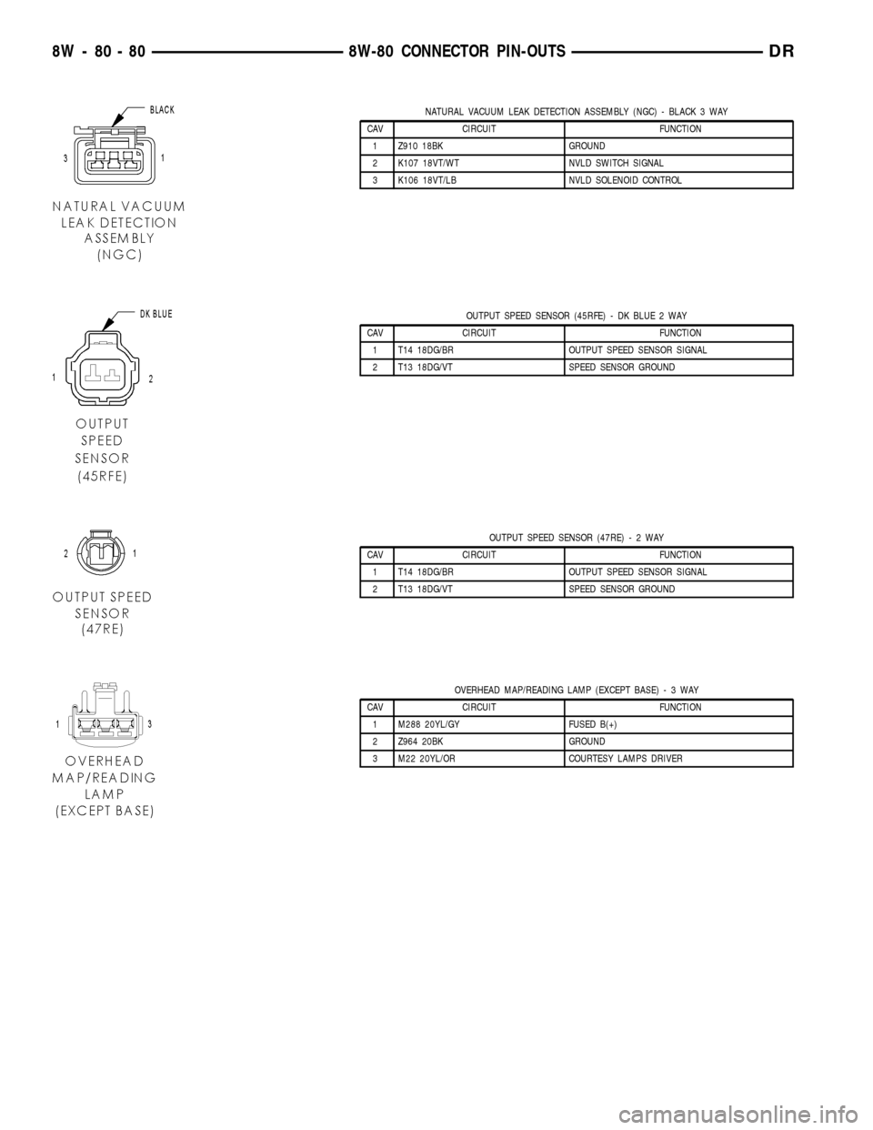
NATURAL VACUUM LEAK DETECTION ASSEMBLY (NGC) - BLACK 3 WAY
CAV CIRCUIT FUNCTION
1 Z910 18BK GROUND
2 K107 18VT/WT NVLD SWITCH SIGNAL
3 K106 18VT/LB NVLD SOLENOID CONTROL
OUTPUT SPEED SENSOR (45RFE) - DK BLUE 2 WAY
CAV CIRCUIT FUNCTION
1 T14 18DG/BR OUTPUT SPEED SENSOR SIGNAL
2 T13 18DG/VT SPEED SENSOR GROUND
OUTPUT SPEED SENSOR (47RE)-2WAY
CAV CIRCUIT FUNCTION
1 T14 18DG/BR OUTPUT SPEED SENSOR SIGNAL
2 T13 18DG/VT SPEED SENSOR GROUND
OVERHEAD MAP/READING LAMP (EXCEPT BASE)-3WAY
CAV CIRCUIT FUNCTION
1 M288 20YL/GY FUSED B(+)
2 Z964 20BK GROUND
3 M22 20YL/OR COURTESY LAMPS DRIVER
8W - 80 - 80 8W-80 CONNECTOR PIN-OUTSDR
Page 1178 of 2627

Fig. 15 TRANSMISSION 45RFE (4X4) (3.7L/4.7L)
DR8W-91 CONNECTOR/GROUND/SPLICE LOCATION 8W - 91 - 25
CONNECTOR/GROUND/SPLICE LOCATION (Continued)
Page 1179 of 2627

Fig. 16 1LEFT TRANSMISSION 45RFE (5.7L)
8W - 91 - 26 8W-91 CONNECTOR/GROUND/SPLICE LOCATIONDR
CONNECTOR/GROUND/SPLICE LOCATION (Continued)
Page 1704 of 2627

TRANSMISSION AND TRANSFER CASE
TABLE OF CONTENTS
page page
MANUAL TRANSMISSION - NV3500..........1
MANUAL TRANSMISSION - NV4500..........43
MANUAL TRANSMISSION - NV5600..........88
AUTOMATIC TRANSMISSION - 48RE........130
AUTOMATIC TRANSMISSION - 45RFE/545RFE.311
TRANSFER CASE - NV241 GENII...........415TRANSFER CASE - NV271................447
TRANSFER CASE - NV243................482
TRANSFER CASE - NV244 GENII...........512
TRANSFER CASE - NV273................542
MANUAL TRANSMISSION - NV3500
TABLE OF CONTENTS
page page
MANUAL TRANSMISSION - NV3500
DESCRIPTION..........................1
OPERATION............................1
DIAGNOSIS AND TESTING................3
REMOVAL.............................3
DISASSEMBLY..........................4CLEANING............................15
INSPECTION..........................16
ASSEMBLY............................17
INSTALLATION.........................39
SPECIFICATIONS.......................40
SPECIAL TOOLS.......................40
MANUAL TRANSMISSION -
NV3500
DESCRIPTION
The transmission is a medium-duty 5-speed, con-
stant mesh fully synchronized manual transmission
with fifth gear overdrive range. The transmission is
available in two and four-wheel drive configurations.
The transmission gear case consists of two aluminum
housings (Fig. 1). The clutch housing is an integral
part of the transmission front housing.
A combination of roller and ball bearings are used
to support the transmission shafts in the two hous-
ings. The transmission gears all rotate on caged type
needle bearings. A roller bearing is used between the
input and output shaft.
The transmission has a single shaft shift mecha-
nism with three shift forks all mounted on the shaft.
The shaft is supported in the front and rear housings
by bushings and one linear ball bearing. Internal
shift components consist of the forks, shaft, shift
lever socket and detent components
OPERATION
The manual transmission receives power through the
clutch assembly from the engine. The clutch disc issplined to the transmission input shaft and is turned at
engine speed at all times that the clutch is engaged.
The input shaft is connected to the transmission coun-
tershaft through the mesh of fourth speed gear on the
input shaft and the fourth countershaft gear. At this
point, all the transmission gears are spinning.
The driver selects a particular gear by moving the
shift lever to the desired gear position. This movement
moves the internal transmission shift components to
begin the shift sequence. As the shift lever moves the
selected shift rail, the shift fork attached to that rail
begins to move. The fork is positioned in a groove in the
outer circumference of the synchronizer sleeve. As the
shift fork moves the synchronizer sleeve, the synchro-
nizer begins to speed-up or slow down the selected gear
(depending on whether we are up-shifting or down-shift-
ing). The synchronizer does this by having the synchro-
nizer hub splined to the mainshaft and moving the
blocker ring into contact with the gear's friction cone. As
the blocker ring and friction cone come together, the
gear speed is brought up or down to the speed of the
synchronizer. As the two speeds match, the splines on
the inside of the synchronizer sleeve become aligned
with the teeth on the blocker ring and the friction cone
and eventually will slide over the teeth, locking the gear
to the mainshaft, or countershaft, through the synchro-
nizer.
DRTRANSMISSION AND TRANSFER CASE 21 - 1
Page 2014 of 2627

AUTOMATIC TRANSMISSION - 45RFE/545RFE
TABLE OF CONTENTS
page page
AUTOMATIC TRANSMISSION - 45RFE/545RFE
DESCRIPTION........................312
OPERATION..........................313
DIAGNOSIS AND TESTING
DIAGNOSIS AND TESTING - AUTOMATIC
TRANSMISSION.....................314
DIAGNOSIS AND TESTING -
PRELIMINARY.......................314
DIAGNOSIS AND TESTING - ROAD
TESTING...........................314
DIAGNOSIS AND TESTING - HYDRAULIC
PRESSURE TEST....................316
DIAGNOSIS AND TESTING - AIR CHECKING
TRANSMISSION CLUTCH OPERATION....317
DIAGNOSIS AND TESTING - CONVERTER
HOUSING FLUID LEAK................318
STANDARD PROCEDURE - ALUMINUM
THREAD REPAIR.....................318
REMOVAL............................318
DISASSEMBLY........................320
CLEANING...........................326
INSPECTION.........................326
ASSEMBLY...........................326
INSTALLATION........................333
SCHEMATICS AND DIAGRAMS
HYDRAULIC SCHEMATICS.............337
SPECIFICATIONS
TRANSMISSION.....................358
SPECIAL TOOLS
RFE TRANSMISSION.................359
4C RETAINER/BULKHEAD
DISASSEMBLY........................362
ASSEMBLY...........................363
ADAPTER HOUSING SEAL
REMOVAL............................364
INSTALLATION........................364
BRAKE TRANSMISSION SHIFT INTERLOCK
SYSTEM
DESCRIPTION........................364
OPERATION..........................364
DIAGNOSIS AND TESTING - BRAKE
TRANSMISSION SHIFT INTERLOCK......364
ADJUSTMENTS - BRAKE TRANSMISSION
SHIFT INTERLOCK...................365
FLUID AND FILTER
DIAGNOSIS AND TESTING
DIAGNOSIS AND TESTING - EFFECTS OF
INCORRECT FLUID LEVEL.............366
DIAGNOSIS AND TESTING - CAUSES OF
BURNT FLUID.......................366DIAGNOSIS AND TESTING - FLUID
CONTAMINATION....................366
STANDARD PROCEDURE
STANDARD PROCEDURE - FLUID LEVEL
CHECK............................366
STANDARD PROCEDURE - FLUID AND
FILTER REPLACEMENT...............367
STANDARD PROCEDURE - TRANSMISSION
FILL...............................368
GEARSHIFT CABLE
DIAGNOSIS AND TESTING - GEARSHIFT
CABLE.............................368
REMOVAL............................369
INSTALLATION........................370
ADJUSTMENTS
GEARSHIFT CABLE..................370
HOLDING CLUTCHES
DESCRIPTION........................371
OPERATION..........................372
INPUT CLUTCH ASSEMBLY
DESCRIPTION........................373
OPERATION..........................373
DISASSEMBLY........................374
ASSEMBLY...........................378
INPUT SPEED SENSOR
DESCRIPTION........................382
OPERATION..........................382
REMOVAL............................382
INSTALLATION........................382
LINE PRESSURE (LP) SENSOR
DESCRIPTION........................382
OPERATION..........................383
REMOVAL............................383
INSTALLATION........................383
LOW/REVERSE CLUTCH
DISASSEMBLY........................384
CLEANING...........................385
INSPECTION.........................385
ASSEMBLY...........................385
OIL PUMP
DESCRIPTION........................386
OPERATION..........................386
STANDARD PROCEDURE - OIL PUMP
VOLUME CHECK.....................387
DISASSEMBLY........................388
CLEANING...........................390
INSPECTION.........................390
ASSEMBLY...........................390
OIL PUMP FRONT SEAL
REMOVAL............................391
DRAUTOMATIC TRANSMISSION - 45RFE/545RFE 21 - 311
Page 2015 of 2627

INSTALLATION........................391
OUTPUT SPEED SENSOR
DESCRIPTION........................391
OPERATION..........................391
REMOVAL............................391
INSTALLATION........................392
TOW/HAUL OVERDRIVE SWITCH
DESCRIPTION........................392
OPERATION..........................392
REMOVAL............................392
INSTALLATION........................393
PISTONS
DESCRIPTION........................393
OPERATION..........................393
PLANETARY GEARTRAIN
DESCRIPTION........................395
OPERATION..........................396
DISASSEMBLY........................396
CLEANING...........................396
INSPECTION.........................397
ASSEMBLY...........................397
SHIFT MECHANISM
DESCRIPTION........................398
OPERATION..........................398
SOLENOID SWITCH VALVE
DESCRIPTION........................398
OPERATION..........................398
SOLENOIDS
DESCRIPTION........................398OPERATION..........................399
TORQUE CONVERTER
DESCRIPTION........................399
OPERATION..........................403
REMOVAL............................404
INSTALLATION........................404
TRANSMISSION CONTROL RELAY
DESCRIPTION........................405
OPERATION..........................405
TRANSMISSION RANGE SENSOR
DESCRIPTION........................405
OPERATION..........................405
TRANSMISSION SOLENOID/TRS ASSEMBLY
DESCRIPTION........................406
OPERATION..........................406
REMOVAL............................407
INSTALLATION........................408
TRANSMISSION TEMPERATURE SENSOR
DESCRIPTION........................408
OPERATION..........................408
VALVE BODY
DESCRIPTION........................408
OPERATION..........................408
REMOVAL............................410
DISASSEMBLY........................410
CLEANING...........................412
INSPECTION.........................413
ASSEMBLY...........................414
INSTALLATION........................414
AUTOMATIC TRANSMISSION -
45RFE/545RFE
DESCRIPTION
The 45RFE/545RFE automatic transmissions is a
sophisticated, multi-range, electronically controlled
transmission which combines optimized gear ratios
for responsive performance, state of the art efficiency
features and low NVH. Other features include driver
adaptive shifting and three planetary gear sets to
provide wide ratio capability with precise ratio steps
for optimum driveability. The three planetary gear
sets also make available a unique alternate second
gear ratio. The primary 2nd gear ratio fits between
1st and 3rd gears for normal through-gear accelera-
tions. The alternate second gear ratio (2prime) allows
smoother 4-2 kickdowns at high speeds to provide
2nd gear passing performance over a wider highway
cruising range.
The hydraulic portion of the transmission consists
of the transmission fluid, fluid passages, hydraulic
valves, and various line pressure control components.The primary mechanical components of the trans-
mission consist of the following:
²Three multiple disc input clutches
²Three multiple disc holding clutches
²Five hydraulic accumulators
²Three planetary gear sets
²Dual Stage Hydraulic oil pump
²Valve body
²Solenoid pack
The TCM is the ªheartº or ªbrainº of the electronic
control system and relies on information from vari-
ous direct and indirect inputs (sensors, switches, etc.)
to determine driver demand and vehicle operating
conditions. With this information, the TCM can cal-
culate and perform timely and quality shifts through
various output or control devices (solenoid pack,
transmission control relay, etc.).
21 - 312 AUTOMATIC TRANSMISSION - 45RFE/545RFEDR
Page 2016 of 2627

TRANSMISSION IDENTIFICATION
Transmission identification numbers are stamped
on the left side of the case just above the oil pan
sealing surface (Fig. 1). Refer to this information
when ordering replacement parts. A label is attached
to the transmission case above the stamped numbers.
The label gives additional information which may
also be necessary for identification purposes.
GEAR RATIOS
The 45RFE gear ratios are:
1st .................................3.00:1
2nd.................................1.67:1
2nd Prime...........................1.50:1
3rd.................................1.00:1
4th .................................0.75:1
Reverse.............................3.00:1
GEAR RATIOS
The 545RFE gear ratios are:
1st .................................3.00:1
2nd.................................1.67:1
2nd Prime...........................1.50:1
3rd.................................1.00:1
4th .................................0.75:1
5th .................................0.67:1
Reverse.............................3.00:1
OPERATION
The 45RFE/545RFE offers full electronic control of
all automatic up and downshifts, and features real-
time adaptive closed-loop shift and pressure control.
Electronic shift and torque converter clutch controls
help protect the transmission from damage due to
high temperatures, which can occur under severe
operating conditions. By altering shift schedules, line
pressure, and converter clutch control, these controls
reduce heat generation and increase transmission
cooling.
To help reduce efficiency-robbing parasitic losses,
the transmissions includes a dual-stage transmission
fluid pump with electronic output pressure control.
Under most driving conditions, pump output pres-
sure greatly exceeds that which is needed to keep the
clutches applied. The 45RFE/545RFE pump-pressure
control system monitors input torque and adjusts the
pump pressure accordingly. The primary stage of the
pump works continuously; the second stage is
bypassed when demand is low. The control system
also monitors input and output speed and, if incipi-
ent clutch slip is observed, the pressure control sole-
noid duty cycle is varied, increasing pressure in
proportion to demand.
A high-travel torque converter damper assembly
allows earlier torque converter clutch engagement to
reduce slippage. Needle-type thrust bearings reduce
internal friction. The 45RFE/545RFE is packaged in
a one-piece die-cast aluminum case. To reduce NVH,
the case has high lateral, vertical and torsional stiff-
ness. It is also designed to maximize the benefit of
the structural dust cover that connects the bottom of
the bell housing to the engine bedplate, enhancing
overall power train stiffness. Dual filters protect the
pump and other components. A pump return filter is
added to the customary main sump filter. Indepen-
dent lubrication and cooler circuits assure ample
pressure for normal transmission operation even if
the cooler is obstructed or the fluid cannot flow due
to extremely low temperatures.
The hydraulic control system design (without elec-
tronic assist) provides the transmission with PARK,
REVERSE, NEUTRAL, SECOND, and THIRD gears,
based solely on driver shift lever selection. This
design allows the vehicle to be driven (in ªlimp-inº
mode) in the event of a electronic control system fail-
ure, or a situation that the Transmission Control
Module (TCM) recognizes as potentially damaging to
the transmission.
The TCM also performs certain self-diagnostic
functions and provides comprehensive information
(sensor data, DTC's, etc.) which is helpful in proper
diagnosis and repair. This information can be viewed
with the DRBtscan tool.
Fig. 1 Transmission Part And Serial Number
Location
1 - IDENTIFICATION NUMBERS (STAMPED)
DRAUTOMATIC TRANSMISSION - 45RFE/545RFE 21 - 313
AUTOMATIC TRANSMISSION - 45RFE/545RFE (Continued)
Page 2017 of 2627

DIAGNOSIS AND TESTING
DIAGNOSIS AND TESTING - AUTOMATIC
TRANSMISSION
CAUTION: Before attempting any repair on a RFE
automatic transmission, check for Diagnostic Trou-
ble Codes with the DRBTscan tool.
Transmission malfunctions may be caused by these
general conditions:
²Poor engine performance
²Improper adjustments
²Hydraulic malfunctions
²Mechanical malfunctions
²Electronic malfunctions
Diagnosis of these problems should always begin
by checking the easily accessible variables: fluid level
and condition, gearshift cable adjustment. Then per-
form a road test to determine if the problem has been
corrected or if more diagnosis is necessary. If the
problem persists after the preliminary tests and cor-
rections are completed, hydraulic pressure checks
should be performed.
DIAGNOSIS AND TESTING - PRELIMINARY
Two basic procedures are required. One procedure
for vehicles that are drivable and an alternate proce-
dure for disabled vehicles (will not back up or move
forward).
VEHICLE IS DRIVABLE
(1) Check for transmission fault codes using DRBt
scan tool.
(2) Check fluid level and condition.
(3) Adjust gearshift cable if complaint was based
on delayed, erratic, or harsh shifts.
(4) Road test and note how transmission upshifts,
downshifts, and engages.
(5) Perform hydraulic pressure test if shift prob-
lems were noted during road test.(6) Perform air-pressure test to check clutch oper-
ation.
VEHICLE IS DISABLED
(1) Check fluid level and condition.
(2) Check for broken or disconnected gearshift
cable.
(3) Check for cracked, leaking cooler lines, or loose
or missing pressure-port plugs.
(4) Raise and support vehicle on safety stands,
start engine, shift transmission into gear, and note
following:
(a) If propeller shaft turns but wheels do not,
problem is with differential or axle shafts.
(b) If propeller shaft does not turn and transmis-
sion is noisy, stop engine. Remove oil pan, and
check for debris. If pan is clear, remove transmis-
sion and check for damaged driveplate, converter,
oil pump, or input shaft.
(c) If propeller shaft does not turn and transmis-
sion is not noisy, perform hydraulic-pressure test to
determine if problem is hydraulic or mechanical.
DIAGNOSIS AND TESTING - ROAD TESTING
Before road testing, be sure the fluid level and con-
trol cable adjustments have been checked and
adjusted if necessary. Verify that all diagnostic trou-
ble codes have been resolved.
Observe engine performance during the road test.
A poorly tuned engine will not allow accurate analy-
sis of transmission operation.
Operate the transmission in all gear ranges. Check
for shift variations and engine flare which indicates
slippage. Note if shifts are harsh, spongy, delayed,
early, or if part throttle downshifts are sensitive.
Slippage indicated by engine flare, usually means
clutch, overrunning clutch, or line pressure problems.
A slipping clutch can often be determined by com-
paring which internal units are applied in the vari-
ous gear ranges. The Clutch Application charts
provide a basis for analyzing road test results.
21 - 314 AUTOMATIC TRANSMISSION - 45RFE/545RFEDR
AUTOMATIC TRANSMISSION - 45RFE/545RFE (Continued)
Page 2018 of 2627

45RFE CLUTCH APPLICATION CHART
SLP UD OD R 2C 4C L/R OVERRUNNING
P±PARKON
R±REVERSEON ON
N-NEUTRALON
D±OVERDRIVE
FIRSTON ON* ON
SECONDON ON
SECOND PRIMEON ON
THIRDON ON
FOURTHON ON
LIMP-INON ON
2±FIRSTON ON* ON
SECONDON ON
LIMP-INON ON
1±LOWON ON ON
*L/R clutch is on only with the output shaft speed below 150 rpm.
545RFE CLUTCH APPLICATION CHART
SLP UD OD R 2C 4C L/R OVERRUNNING
P±PARKON
R±REVERSEON ON
N-NEUTRALON
D±OVERDRIVE
FIRSTON ON* ON
SECONDON ON
SECOND PRIMEON ON
THIRDON ON
FOURTHON ON
FIFTHON ON
LIMP-INON ON
2±FIRSTON ON* ON
SECONDON ON
LIMP-INON ON
1±LOWON ON ON
*L/R clutch is on only with the output shaft speed below 150 rpm.
DRAUTOMATIC TRANSMISSION - 45RFE/545RFE 21 - 315
AUTOMATIC TRANSMISSION - 45RFE/545RFE (Continued)