Auto shut down relay DODGE RAM 1500 1998 2.G User Guide
[x] Cancel search | Manufacturer: DODGE, Model Year: 1998, Model line: RAM 1500, Model: DODGE RAM 1500 1998 2.GPages: 2627
Page 733 of 2627
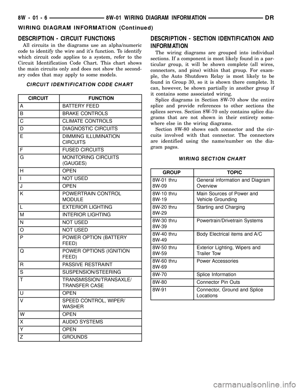
DESCRIPTION - CIRCUIT FUNCTIONS
All circuits in the diagrams use an alpha/numeric
code to identify the wire and it's function. To identify
which circuit code applies to a system, refer to the
Circuit Identification Code Chart. This chart shows
the main circuits only and does not show the second-
ary codes that may apply to some models.
CIRCUIT IDENTIFICATION CODE CHART
CIRCUIT FUNCTION
A BATTERY FEED
B BRAKE CONTROLS
C CLIMATE CONTROLS
D DIAGNOSTIC CIRCUITS
E DIMMING ILLUMINATION
CIRCUITS
F FUSED CIRCUITS
G MONITORING CIRCUITS
(GAUGES)
H OPEN
I NOT USED
J OPEN
K POWERTRAIN CONTROL
MODULE
L EXTERIOR LIGHTING
M INTERIOR LIGHTING
N NOT USED
O NOT USED
P POWER OPTION (BATTERY
FEED)
Q POWER OPTIONS (IGNITION
FEED)
R PASSIVE RESTRAINT
S SUSPENSION/STEERING
T TRANSMISSION/TRANSAXLE/
TRANSFER CASE
U OPEN
V SPEED CONTROL, WIPER/
WASHER
W OPEN
X AUDIO SYSTEMS
Y OPEN
Z GROUNDS
DESCRIPTION - SECTION IDENTIFICATION AND
INFORMATION
The wiring diagrams are grouped into individual
sections. If a component is most likely found in a par-
ticular group, it will be shown complete (all wires,
connectors, and pins) within that group. For exam-
ple, the Auto Shutdown Relay is most likely to be
found in Group 30, so it is shown there complete. It
can, however, be shown partially in another group if
it contains some associated wiring.
Splice diagrams in Section 8W-70 show the entire
splice and provide references to other sections the
splices serves. Section 8W-70 only contains splice dia-
grams that are not shown in their entirety some-
where else in the wiring diagrams.
Section 8W-80 shows each connector and the cir-
cuits involved with that connector. The connectors
are identified using the name/number on the dia-
gram pages.
WIRING SECTION CHART
GROUP TOPIC
8W-01 thru
8W-09General information and Diagram
Overview
8W-10 thru
8W-19Main Sources of Power and
Vehicle Grounding
8W-20 thru
8W-29Starting and Charging
8W-30 thru
8W-39Powertrain/Drivetrain Systems
8W-40 thru
8W-49Body Electrical items and A/C
8W-50 thru
8W-59Exterior Lighting, Wipers and
Trailer Tow
8W-60 thru
8W-69Power Accessories
8W-70 Splice Information
8W-80 Connector Pin Outs
8W-91 Connector, Ground and Splice
Locations
8W - 01 - 6 8W-01 WIRING DIAGRAM INFORMATIONDR
WIRING DIAGRAM INFORMATION (Continued)
Page 744 of 2627

8W-02 COMPONENT INDEX
Component Page
A/C Compressor Clutch................. 8W-42
A/C Compressor Clutch Relay............ 8W-42
A/C Pressure Transducer................ 8W-42
A/C-Heater Control.................... 8W-42
Accelerator Pedal Position Sensor......... 8W-30
Adjustable Pedal Motor................. 8W-30
Adjustable Pedal Relay................. 8W-30
Adjustable Pedal Switch................ 8W-30
Airbag Control Module................. 8W-43
Airbag-Squibs........................ 8W-43
Airbag-Curtains....................... 8W-43
Airbag-Passenger On/Off Switch.......... 8W-43
Ambient Temperature Sensor............ 8W-49
Amplifier Audio....................... 8W-47
Ashtray Lamp........................ 8W-44
Auto Shut Down Relay................. 8W-30
Automatic Day/Night Mirror.......... 8W-49, 55
Auxiliary Battery..................... 8W-20
Backup Lamp Switch.................. 8W-51
Battery............................. 8W-20
Battery Temperature Sensor............. 8W-30
Blend Door Actuators.................. 8W-42
Blower Motor......................... 8W-42
Blower Motor Resistor Block............. 8W-42
Brake Fluid Level Switch............ 8W-34, 35
Brake Lamp Switch.................... 8W-33
Brake Transmission Shift Interlock
Solenoid........................... 8W-40
Camshaft Position Sensor............... 8W-30
Capacitor............................ 8W-30
Center High Mounted Stop Lamp-
Aftermarket........................ 8W-51
Center High Mounted Stop Lamp/Cargo
Lamp.......................... 8W-44, 51
Cigar Lighter Outlet................... 8W-41
Circuit Breaker....................... 8W-10
Clearance Lamps...................... 8W-50
Clockspring................. 8W-33, 41, 43, 47
Clutch Interlock Brake Switch........... 8W-21
Coil On Plugs........................ 8W-30
Compass/Mini-Trip Computer............ 8W-49
Condenser Fan....................... 8W-42
Condenser Fan Relay.................. 8W-42
Controller Antilock Brake............ 8W-34, 35
Crankshaft Position Sensor.............. 8W-30
Cylinder Lock Switch-Driver............. 8W-61
Data Link Connector................... 8W-18
Data Link Connector-Engine............. 8W-18
Dome Lamp....................... 8W-44, 49
Door Ajar Switches.................... 8W-40
Door Lock Motor/Ajar Switches........ 8W-40, 61
Door Lock Switch-Passenger............. 8W-61Component Page
Door Module................... 8W-60, 61, 62
EGR Solenoid........................ 8W-30
Electric Backlight..................... 8W-48
Electric Brake Provision................ 8W-54
Electronic Throttle Control Module........ 8W-30
Engine Control Module................. 8W-30
Engine Coolant Temperature Sensor....... 8W-30
Engine Oil Pressure Switch.............. 8W-30
EVAP/Purge Solenoid.................. 8W-30
Evaporator Temperature Sensor.......... 8W-42
Fender Lamps........................ 8W-51
Fog Lamp Relay...................... 8W-50
Fog Lamps.......................... 8W-50
Front Control Module.................. 8W-10
Fuel Control Actuator.................. 8W-30
Fuel Heater.......................... 8W-30
Fuel Heater Relay..................... 8W-30
Fuel Injector Packs.................... 8W-30
Fuel Injectors........................ 8W-30
Fuel Pump Module.................... 8W-30
Fuel Pump Motor..................... 8W-30
Fuel Pump Relay...................... 8W-30
Fuses............................ 8W-10, 33
Fusible Link......................... 8W-10
Generator........................... 8W-20
Glove Box Lamp And Switch............. 8W-44
Grounds............................ 8W-15
Hands Free Module.................... 8W-55
Headlamp Switch.................. 8W-40, 50
Headlamps.......................... 8W-50
Heated Mirror Relay................... 8W-62
Heated Seat Cushions.................. 8W-63
Horn Relay.......................... 8W-41
Horn Switch......................... 8W-41
Horn-High Note....................... 8W-41
Horn-Low Note....................... 8W-41
Idle Air Control Motor.................. 8W-30
Ignition Switch....................... 8W-10
Inlet Air Temperature Sensor............ 8W-30
Input Speed Sensor.................... 8W-31
Instrument Cluster.................... 8W-40
Intake Air Heater Relays............... 8W-30
Intake Air Temperature Sensor........... 8W-30
Intake Air Temperature/Manifold Absolute
Pressure Sensor..................... 8W-30
Integrated Power Module............... 8W-10
Knock Sensosr........................ 8W-30
License Lamps....................... 8W-51
Lift Pump Motor...................... 8W-30
Line Pressure Sensor................ 8W-30, 31
Lumbar Motors....................... 8W-63
Lumbar Switch....................... 8W-63
DR8W-02 COMPONENT INDEX 8W - 02 - 1
Page 746 of 2627

8W-10 POWER DISTRIBUTION
Component Page
A/C Compressor Clutch....................8W-10-17, 40
A/C Compressor Clutch Relay.................8W-10-17, 40
A/C-Heater Control....................8W-10-42, 43, 49
Adjustable Pedal Relay....................8W-10-15, 32
Adjustable Pedal Switch..................8W-10-15, 32, 42
Airbag Control Module.....................8W-10-42, 44
Airbag-Passenger On/Off Switch.................8W-10-42
Ambient Temperature Sensor.................8W-10-48, 50
Amplifier Audio..........................8W-10-31
Ashtray Lamp...........................8W-10-35
Auto Shut Down Relay....................8W-10-12, 19
Automatic Day/Night Mirror.................8W-10-41, 48
Auxiliary Battery.........................8W-10-12
Backup Lamp Switch.....................8W-10-44, 49
Battery.............................8W-10-12, 19
Blower Motor............................8W-10-52
Brake Lamp Switch....................8W-10-14, 30, 40
Capacitor..............................8W-10-22
Cigar Lighter Outlet........................8W-10-46
Circuit Breaker...........................8W-10-52
Clearance Lamp No. 1.......................8W-10-35
Clearance Lamp No. 2.......................8W-10-35
Clearance Lamp No. 3.......................8W-10-35
Clearance Lamp No. 4.......................8W-10-35
Clearance Lamp No. 5.......................8W-10-35
Clutch Interlock Brake Switch..................8W-10-37
Coil On Plug No. 1.......................8W-10-20, 23
Coil On Plug No. 2.......................8W-10-21, 22
Coil On Plug No. 3.......................8W-10-20, 23
Coil On Plug No. 4.......................8W-10-21, 22
Coil On Plug No. 5.......................8W-10-20, 23
Coil On Plug No. 6.......................8W-10-21, 22
Coil On Plug No. 7.......................8W-10-20, 23
Coil On Plug No. 8.......................8W-10-21, 22
Compass/Mini-Trip Computer...............8W-10-31, 39, 41
Condenser Fan.........................8W-10-18, 45
Condenser Fan Relay.....................8W-10-18, 45
Controller Antilock Brake.................8W-10-14, 28, 44
Data Link Connector......................8W-10-30, 50
Door Lock Switch-Passenger....................8W-10-41
Driver Door Module....................8W-10-15, 32, 52
Electric Backlight.........................8W-10-49
Electric Brake Provision....................8W-10-12, 19
Engine Control Module................8W-10-12, 26, 38, 40
Fender Lamp-Front Left......................8W-10-35
Fender Lamp-Front Right.....................8W-10-35
Fender Lamp-Rear Left......................8W-10-35
Fender Lamp-Rear Right.....................8W-10-35
Fog Lamp Relay........................8W-10-16, 36
Fog Lamp-Left...........................8W-10-36
Fog Lamp-Right..........................8W-10-36
Front Control Module . 8W-10-13, 26, 29, 30, 32, 33, 34, 36, 47, 48, 50, 51
Fuel Heater............................8W-10-53
Fuel Heater Relay.....................8W-10-18, 40, 53
Fuel Injector No. 1.......................8W-10-23, 24
Fuel Injector No. 2.......................8W-10-21, 22
Fuel Injector No. 3.......................8W-10-23, 24
Fuel Injector No. 4.......................8W-10-21, 22
Fuel Injector No. 5.......................8W-10-23, 24
Fuel Injector No. 6.......................8W-10-21, 22
Fuel Injector No. 7.......................8W-10-23, 24
Fuel Injector No. 8.......................8W-10-21, 22
Fuel Pump Module.......................8W-10-17, 39
Fuel Pump Relay......................8W-10-17, 39, 40
Fuse 1.............................8W-10-12, 19
Fuse 2...........................8W-10-12, 13, 19
Fuse 3.............................8W-10-13, 25
Fuse 4.............................8W-10-13, 25
Fuse 5.......................8W-10-12, 13, 14, 26, 27
Fuse 6...........................8W-10-13, 14, 28
Fuse 7.............................8W-10-14, 28
Fuse 8.............................8W-10-15, 29
Fuse 9.............................8W-10-13, 25
Fuse 10.............................8W-10-13, 25
Fuse 11...........................8W-10-13, 14, 30
Fuse 12...........................8W-10-18, 45, 53
Fuse 13.............................8W-10-13, 30
Fuse 14.............................8W-10-15, 37
Fuse 15...........................8W-10-16, 17, 34
Fuse 16.............................8W-10-17, 40
Fuse 17...........................8W-10-17, 18, 39
Fuse 18.............................8W-10-14, 30
Fuse 19.............................8W-10-14, 31
Fuse 20.............................8W-10-13, 25
Fuse 21.............................8W-10-14, 31
Fuse 22.............................8W-10-14, 31
Fuse 23.............................8W-10-14, 31
Fuse 24.............................8W-10-14, 30Component Page
Fuse 25.............................8W-10-14, 31
Fuse 26...............................8W-10-49
Fuse 27...........................8W-10-17, 18, 43
Fuse 28.............................8W-10-40, 41
Fuse 29...............................8W-10-46
Fuse 32.............................8W-10-17, 34
Fuse 33.............................8W-10-17, 34
Fuse 34.............................8W-10-17, 34
Fuse 35...............................8W-10-44
Fuse 36...............................8W-10-43
Fuse 37...............................8W-10-44
Fuse 38.............................8W-10-43, 44
Fuse 40...........................8W-10-15, 16, 32
Fuse 41.............................8W-10-16, 36
Fuse 42.............................8W-10-14, 32
Fuse 43.............................8W-10-14, 32
Fuse 45...........................8W-10-16, 17, 36
Fuse 46...........................8W-10-15, 16, 33
Fuse 47.............................8W-10-16, 33
Fuse 48.............................8W-10-15, 32
Fuse 49.............................8W-10-12, 19
Fuse 50.............................8W-10-26, 40
Fuse 51...........................8W-10-14, 15, 30
Fuse 52.............................8W-10-43, 44
Fuse 53...............................8W-10-41
Fusible Link............................8W-10-12
G104........................8W-10-27, 29, 47, 48, 53
G201................................8W-10-25
Generator..............................8W-10-12
Headlamp Switch.........................8W-10-36
Headlamp-Left...........................8W-10-51
Headlamp-Right..........................8W-10-51
Heated Mirror Relay......................8W-10-18, 43
Horn Relay...........................8W-10-16, 36
Horn-High Note..........................8W-10-36
Horn-Low Note...........................8W-10-36
Ignition Switch...............8W-10-13, 25, 37, 41, 44, 46, 52
Instrument Cluster............8W-10-14, 25, 30, 31, 41, 46, 52
Integrated Power Module . . 8W-10-3, 4, 12, 13, 14, 15, 16, 17, 18, 19, 25,
26, 27, 28, 29, 30, 31, 32, 33, 34, 36, 37, 39, 40, 41, 42, 43, 44, 45, 46,
47, 48, 49, 50, 51, 53
License Lamp-Left.........................8W-10-34
License Lamp-Right........................8W-10-34
Oxygen Sensor Downstream Relay..............8W-10-12, 19
Park Lamp Relay.......................8W-10-17, 34
Park/Turn Signal Lamp-Left Front..............8W-10-34, 47
Park/Turn Signal Lamp-Right Front.............8W-10-34, 47
Passenger Lumbar Switch.....................8W-10-28
Power Mirror-Left.........................8W-10-43
Power Mirror-Right........................8W-10-43
Power Outlet..........................8W-10-14, 31
Power Outlet-Console.....................8W-10-14, 32
Power Seat Switch-Driver.....................8W-10-28
Power Seat Switch-Passenger...................8W-10-28
Power Window Circuit Breaker..................8W-10-52
Powertrain Control Module . . 8W-10-18, 19, 22, 27, 31, 37, 39, 40, 45, 52
PTCNo.1 .........................8W-10-39, 40, 41
PTCNo.2 .............................8W-10-46
PTCNo.5 .............................8W-10-33
Radio..............................8W-10-30, 46
Rear Window Defogger Relay...................8W-10-49
Seat Belt Tensioner Reducer....................8W-10-46
Seat Heater Interface Module...................8W-10-32
Sentry Key Immobilizer Module..............8W-10-31, 39, 40
Starter Motor..........................8W-10-15, 37
Starter Motor Relay......................8W-10-15, 37
Tail/Stop/Turn Signal Lamp-Left...........8W-10-34, 47, 48, 50
Tail/Stop/Turn Signal Lamp-Right..........8W-10-35, 47, 48, 50
Tailgate Lamp...........................8W-10-34
Trailer Tow Connector.................8W-10-16, 17, 33, 34
Trailer Tow Connector-Add On..........8W-10-14, 31, 33, 34, 48
Trailer Tow Left Turn Relay..................8W-10-16, 33
Trailer Tow Right Turn Relay.................8W-10-16, 33
Transfer Case Control Module...............8W-10-14, 32, 37
Transfer Case Selector Switch...................8W-10-41
Transmission Control Relay................8W-10-13, 26, 27
Transmission Range Sensor................8W-10-38, 44, 49
Transmission Solenoid Assembly.................8W-10-26
Transmission Solenoid/TRS Assembly...........8W-10-27, 44, 49
Underhood Lamp..........................8W-10-30
Vistronic Fan Drive........................8W-10-43
Washer Fluid Level Switch....................8W-10-48
Washer Pump Motor-Front....................8W-10-48
Wiper High/Low Relay.....................8W-10-15, 29
Wiper Motor-Front.......................8W-10-29, 48
Wiper On/Off Relay......................8W-10-15, 29
DR8W-10 POWER DISTRIBUTION 8W - 10 - 1
Page 832 of 2627

8W-30 FUEL/IGNITION SYSTEM
Component Page
A/C Compressor Clutch Relay............ 8W-30-9, 58
A/C Pressure Transducer......... 8W-30-23, 28, 29, 45
Accelerator Pedal Position Sensor . . . 8W-30-29, 47, 64, 65
Adjustable Pedal Motor................. 8W-30-61
Adjustable Pedal Relay.................. 8W-30-61
Adjustable Pedal Switch................. 8W-30-61
Ambient Temperature Sensor............. 8W-30-30
Auto Shut Down Relay................... 8W-30-4
Battery............................ 8W-30-52
Battery Temperature Sensor............ 8W-30-12, 56
Brake Lamp Switch............. 8W-30-8, 36, 57, 63
Camshaft Position Sensor........ 8W-30-10, 29, 45, 46
Capacitor........................... 8W-30-13
Clockspring..................... 8W-30-8, 36, 59
Coil On Plug No. 1.................. 8W-30-14, 39
Coil On Plug No. 2.................. 8W-30-15, 37
Coil On Plug No. 3.................. 8W-30-14, 39
Coil On Plug No. 4.................. 8W-30-15, 37
Coil On Plug No. 5.................. 8W-30-16, 39
Coil On Plug No. 6.................. 8W-30-13, 37
Coil On Plug No. 7.................. 8W-30-16, 39
Coil On Plug No. 8.................. 8W-30-13, 37
Condenser Fan Relay.................... 8W-30-9
Controller Antilock Brake............ 8W-30-6, 11, 57
Crankshaft Position Sensor............ 8W-30-10, 46
Data Link Connector............... 8W-30-9, 22, 55
Data Link Connector-Engine.............. 8W-30-51
EGR Solenoid................... 8W-30-28, 29, 32
Electronic Throttle Control Module.......... 8W-30-35
Engine Control Module....... 8W-30-42, 43, 44, 45, 46,
47, 48, 49, 50, 51, 52, 53, 54,
55, 56, 57, 58, 59, 60, 62, 63, 64, 65
Engine Coolant Temperature Sensor.... 8W-30-23, 41, 47
Engine Oil Pressure Switch.......... 8W-30-2, 53, 56
EVAP/Purge Solenoid................... 8W-30-12
Front Control Module................... 8W-30-61
Fuel Control Actuator................... 8W-30-50
Fuel Heater......................... 8W-30-60
Fuel Heater Relay..................... 8W-30-60
Fuel Injector No. 1.................. 8W-30-14, 40
Fuel Injector No. 2.................. 8W-30-15, 38
Fuel Injector No. 3.................. 8W-30-14, 40
Fuel Injector No. 4.................. 8W-30-15, 38
Fuel Injector No. 5.................. 8W-30-14, 40
Fuel Injector No. 6.................. 8W-30-15, 38
Fuel Injector No. 7.................. 8W-30-16, 40
Fuel Injector No. 8.................. 8W-30-13, 38
Fuel Injector Pack No. 1................. 8W-30-42
Fuel Injector Pack No. 2............ 8W-30-42, 43, 44
Fuel Injector Pack No. 3................. 8W-30-44
Fuel Pump Module................... 8W-30-3, 58
Fuel Pump Motor...................... 8W-30-48
Fuel Pump Relay....................... 8W-30-3
Fuse 2.............................. 8W-30-4
Fuse 5........................... 8W-30-25, 62
Fuse 12............................ 8W-30-60
Fuse 17............................. 8W-30-3
Fuse 19............................ 8W-30-52
Fuse 23............................. 8W-30-2Component Page
Fuse 36.......................... 8W-30-54, 61
Fuse 40............................ 8W-30-61
Fuse 49............................. 8W-30-4
Fuse 50..................... 8W-30-2, 55, 58, 62
Fusible Link......................... 8W-30-52
G104........................ 8W-30-3, 8, 25, 60
G105............................ 8W-30-56, 58
G107........... 8W-30-2, 7, 15, 18, 19, 20, 21, 30, 32
G114 .............................. 8W-30-53
G120............................ 8W-30-51, 60
G201............................... 8W-30-6
G202.............................. 8W-30-61
Generator......................... 8W-30-7, 51
Idle Air Control Motor................... 8W-30-9
Ignition Switch..................... 8W-30-6, 22
Inlet Air Temperature Sensor............. 8W-30-49
Input Speed Sensor.................... 8W-30-24
Instrument Cluster.................... 8W-30-30
Intake Air Heater Relay No. 1............. 8W-30-56
Intake Air Heater Relay No. 2............. 8W-30-56
Intake Air Temperature Sensor.......... 8W-30-23, 41
Intake Air Temperature/Manifold Absolute
Pressure Sensor..................... 8W-30-50
Integrated Power Module.... 8W-30-2, 3, 4, 9, 25, 52, 54,
55, 58, 60, 61, 62, 64
Knock Sensor........................ 8W-30-31
Knock Sensor-Left..................... 8W-30-33
Knock Sensor-Right.................... 8W-30-33
Lift Pump Motor...................... 8W-30-51
Line Pressure Sensor................... 8W-30-17
Manifold Absolute Pressure Sensor..... 8W-30-23, 29, 41
Natural Vacuum Leak Detection Assembly..... 8W-30-7
Output Speed Sensor................. 8W-30-24, 62
Oxygen Sensor 1/1 Upstream........... 8W-30-20, 21
Oxygen Sensor 1/2 Downstream......... 8W-30-18, 19
Oxygen Sensor 2/1 Upstream........... 8W-30-20, 21
Oxygen Sensor 2/2 Downstream......... 8W-30-18, 19
Oxygen Sensor Downstream Relay........... 8W-30-4
Power Steering Pressure Switch............ 8W-30-7
Powertrain Control Module....... 8W-30-2, 3, 4, 5, 6, 7,
8, 9, 10, 11, 12, 13, 14, 15, 16,
17, 18, 19, 20, 21, 22, 23, 24,
25, 26, 27, 28, 29, 30, 31, 32,
33, 35, 36, 37, 38, 39, 40, 41
PTCNo.1 ....................... 8W-30-3, 9, 58
Pto Switch........................... 8W-30-6
Speed Control Servo.................. 8W-30-8, 63
Speed Control Switch-Left............. 8W-30-36, 59
Speed Control Switch-Right............ 8W-30-36, 59
Starter Motor Relay.................. 8W-30-2, 64
Throttle Position Sensor................. 8W-30-17
Tow/Haul Overdrive Switch............. 8W-30-6, 64
Transmission Control Relay............ 8W-30-25, 62
Transmission Range Sensor............... 8W-30-64
Transmission Solenoid Assembly......... 8W-30-54, 62
Transmission Solenoid/TRS Assembly . 8W-30-5, 25, 26, 27
Vacuum Pump........................ 8W-30-58
Vistronic Fan Drive.................... 8W-30-54
Water In Fuel Sensor................ 8W-30-47, 48
DR8W-30 FUEL/IGNITION SYSTEM 8W - 30 - 1
Page 1093 of 2627
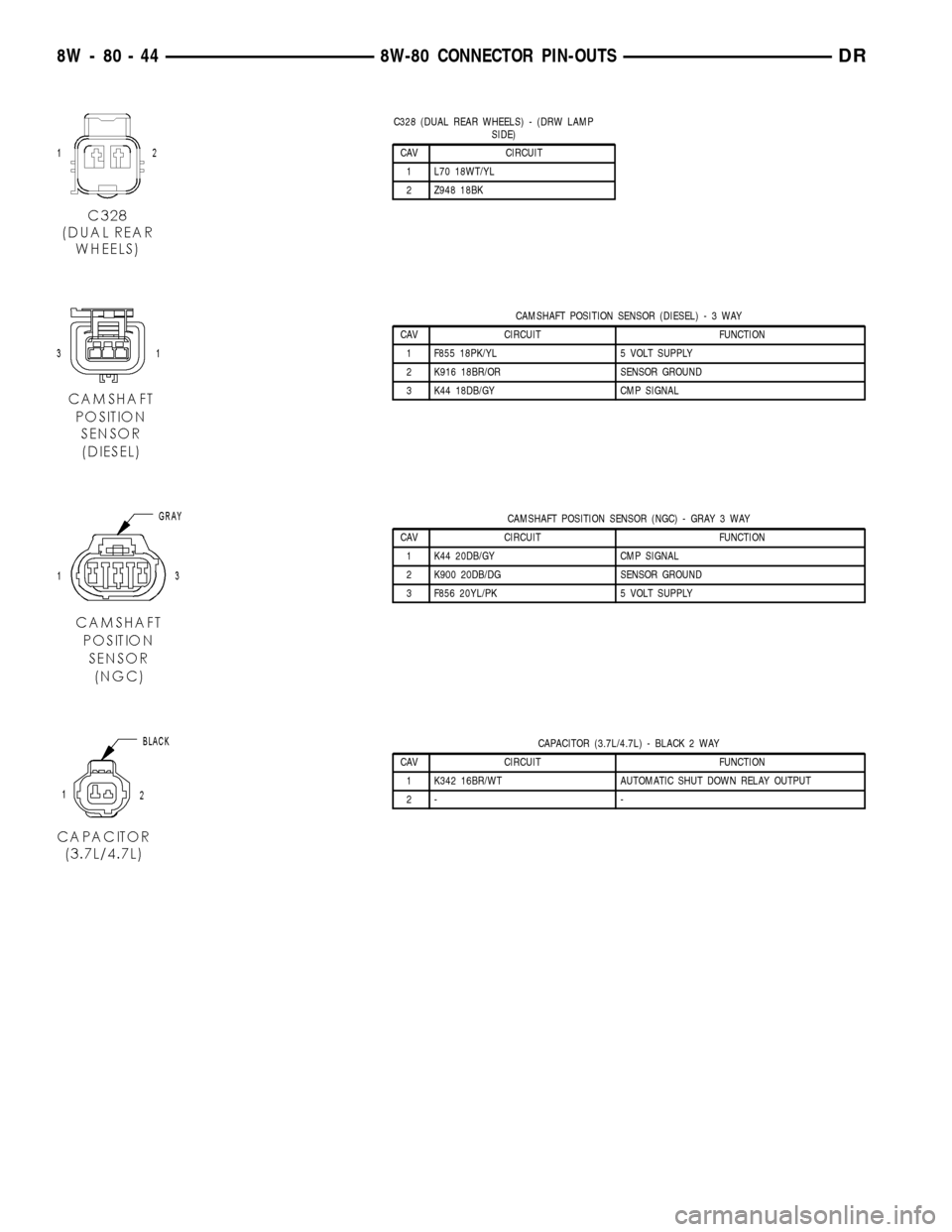
C328 (DUAL REAR WHEELS) - (DRW LAMP
SIDE)
CAV CIRCUIT
1 L70 18WT/YL
2 Z948 18BK
CAMSHAFT POSITION SENSOR (DIESEL)-3WAY
CAV CIRCUIT FUNCTION
1 F855 18PK/YL 5 VOLT SUPPLY
2 K916 18BR/OR SENSOR GROUND
3 K44 18DB/GY CMP SIGNAL
CAMSHAFT POSITION SENSOR (NGC) - GRAY 3 WAY
CAV CIRCUIT FUNCTION
1 K44 20DB/GY CMP SIGNAL
2 K900 20DB/DG SENSOR GROUND
3 F856 20YL/PK 5 VOLT SUPPLY
CAPACITOR (3.7L/4.7L) - BLACK 2 WAY
CAV CIRCUIT FUNCTION
1 K342 16BR/WT AUTOMATIC SHUT DOWN RELAY OUTPUT
2- -
8W - 80 - 44 8W-80 CONNECTOR PIN-OUTSDR
Page 1231 of 2627
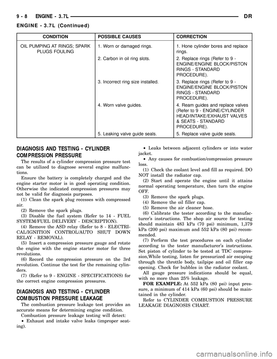
CONDITION POSSIBLE CAUSES CORRECTION
OIL PUMPING AT RINGS; SPARK
PLUGS FOULING1. Worn or damaged rings. 1. Hone cylinder bores and replace
rings.
2. Carbon in oil ring slots. 2. Replace rings (Refer to 9 -
ENGINE/ENGINE BLOCK/PISTON
RINGS - STANDARD
PROCEDURE).
3. Incorrect ring size installed. 3. Replace rings (Refer to 9 -
ENGINE/ENGINE BLOCK/PISTON
RINGS - STANDARD
PROCEDURE).
4. Worn valve guides. 4. Ream guides and replace valves
(Refer to 9 - ENGINE/CYLINDER
HEAD/INTAKE/EXHAUST VALVES
& SEATS - STANDARD
PROCEDURE).
5. Leaking valve guide seals. 5. Replace valve guide seals.
DIAGNOSIS AND TESTING - CYLINDER
COMPRESSION PRESSURE
The results of a cylinder compression pressure test
can be utilized to diagnose several engine malfunc-
tions.
Ensure the battery is completely charged and the
engine starter motor is in good operating condition.
Otherwise the indicated compression pressures may
not be valid for diagnosis purposes.
(1) Clean the spark plug recesses with compressed
air.
(2) Remove the spark plugs.
(3) Disable the fuel system (Refer to 14 - FUEL
SYSTEM/FUEL DELIVERY - DESCRIPTION).
(4) Remove the ASD relay (Refer to 8 - ELECTRI-
CAL/IGNITION CONTROL/AUTO SHUT DOWN
RELAY - REMOVAL).
(5) Insert a compression pressure gauge and rotate
the engine with the engine starter motor for three
revolutions.
(6) Record the compression pressure on the 3rd
revolution. Continue the test for the remaining cylin-
ders.
(7) (Refer to 9 - ENGINE - SPECIFICATIONS) for
the correct engine compression pressures.
DIAGNOSIS AND TESTING - CYLINDER
COMBUSTION PRESSURE LEAKAGE
The combustion pressure leakage test provides an
accurate means for determining engine condition.
Combustion pressure leakage testing will detect:
²Exhaust and intake valve leaks (improper seat-
ing).²Leaks between adjacent cylinders or into water
jacket.
²Any causes for combustion/compression pressure
loss.
(1) Check the coolant level and fill as required. DO
NOT install the radiator cap.
(2) Start and operate the engine until it attains
normal operating temperature, then turn the engine
OFF.
(3) Remove the spark plugs.
(4) Remove the oil filler cap.
(5) Remove the air cleaner hose.
(6) Calibrate the tester according to the manufac-
turer's instructions. The shop air source for testing
should maintain 483 kPa (70 psi) minimum, 1,379
kPa (200 psi) maximum and 552 kPa (80 psi) recom-
mended.
(7) Perform the test procedures on each cylinder
according to the tester manufacturer's instructions.
Set piston of cylinder to be tested at TDC compres-
sion,While testing, listen for pressurized air escaping
through the throttle body, tailpipe and oil filler cap
opening. Check for bubbles in the radiator coolant.
All gauge pressure indications should be equal,
with no more than 25% leakage.
FOR EXAMPLE:At 552 kPa (80 psi) input pres-
sure, a minimum of 414 kPa (60 psi) should be main-
tained in the cylinder.
Refer to CYLINDER COMBUSTION PRESSURE
LEAKAGE DIAGNOSIS CHART.
9 - 8 ENGINE - 3.7LDR
ENGINE - 3.7L (Continued)
Page 1316 of 2627
DIAGNOSIS AND TESTING - CYLINDER
COMPRESSION PRESSURE
The results of a cylinder compression pressure test
can be utilized to diagnose several engine malfunc-
tions.
Ensure the battery is completely charged and the
engine starter motor is in good operating condition.
Otherwise the indicated compression pressures may
not be valid for diagnosis purposes.
(1) Clean the spark plug recesses with compressed
air.
(2) Remove the spark plugs.
(3) Disable the fuel system (Refer to 14 - FUEL
SYSTEM/FUEL DELIVERY - DESCRIPTION).
(4) Remove the ASD relay (Refer to 8 - ELECTRI-
CAL/IGNITION CONTROL/AUTO SHUT DOWN
RELAY - REMOVAL).
(5) Insert a compression pressure gauge and rotate
the engine with the engine starter motor for three
revolutions.
(6)
Record the compression pressure on the 3rd revo-
lution. Continue the test for the remaining cylinders.
(7) (Refer to 9 - ENGINE - SPECIFICATIONS) for
the correct engine compression pressures.
DIAGNOSIS AND TESTING - CYLINDER
COMBUSTION PRESSURE LEAKAGE
The combustion pressure leakage test provides an
accurate means for determining engine condition.
Combustion pressure leakage testing will detect:
²
Exhaust and intake valve leaks (improper seating).
²Leaks between adjacent cylinders or into water
jacket.
²Any causes for combustion/compression pressure
loss.
(1) Check the coolant level and fill as required. DO
NOT install the radiator cap.
(2) Start and operate the engine until it attains
normal operating temperature, then turn the engine
OFF.
(3) Remove the spark plugs.
(4) Remove the oil filler cap.
(5) Remove the air cleaner hose.
(6) Calibrate the tester according to the manufac-
turer's instructions. The shop air source for testing
should maintain 483 kPa (70 psi) minimum, 1,379
kPa (200 psi) maximum and 552 kPa (80 psi) recom-
mended.
(7) Perform the test procedures on each cylinder
according to the tester manufacturer's instructions.
Set piston of cylinder to be tested at TDC compres-
sion,While testing, listen for pressurized air escaping
through the throttle body, tailpipe and oil filler cap
opening. Check for bubbles in the radiator coolant.
All gauge pressure indications should be equal,
with no more than 25% leakage.
FOR EXAMPLE:At 552 kPa (80 psi) input pres-
sure, a minimum of 414 kPa (60 psi) should be main-
tained in the cylinder.
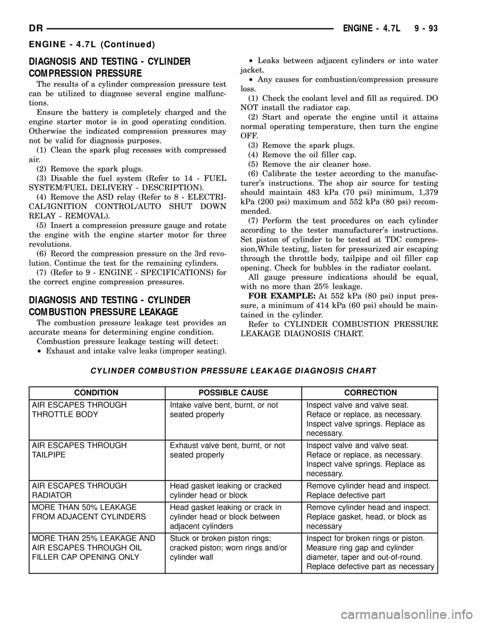
Refer to CYLINDER COMBUSTION PRESSURE
LEAKAGE DIAGNOSIS CHART.
CYLINDER COMBUSTION PRESSURE LEAKAGE DIAGNOSIS CHART
CONDITION POSSIBLE CAUSE CORRECTION
AIR ESCAPES THROUGH
THROTTLE BODYIntake valve bent, burnt, or not
seated properlyInspect valve and valve seat.
Reface or replace, as necessary.
Inspect valve springs. Replace as
necessary.
AIR ESCAPES THROUGH
TAILPIPEExhaust valve bent, burnt, or not
seated properlyInspect valve and valve seat.
Reface or replace, as necessary.
Inspect valve springs. Replace as
necessary.
AIR ESCAPES THROUGH
RADIATORHead gasket leaking or cracked
cylinder head or blockRemove cylinder head and inspect.
Replace defective part
MORE THAN 50% LEAKAGE
FROM ADJACENT CYLINDERSHead gasket leaking or crack in
cylinder head or block between
adjacent cylindersRemove cylinder head and inspect.
Replace gasket, head, or block as
necessary
MORE THAN 25% LEAKAGE AND
AIR ESCAPES THROUGH OIL
FILLER CAP OPENING ONLYStuck or broken piston rings;
cracked piston; worn rings and/or
cylinder wallInspect for broken rings or piston.
Measure ring gap and cylinder
diameter, taper and out-of-round.
Replace defective part as necessary
DRENGINE - 4.7L 9 - 93
ENGINE - 4.7L (Continued)
Page 1409 of 2627
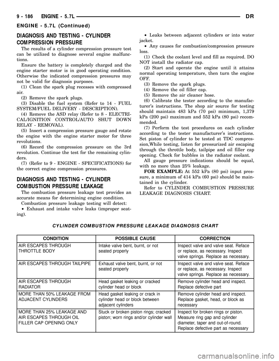
DIAGNOSIS AND TESTING - CYLINDER
COMPRESSION PRESSURE
The results of a cylinder compression pressure test
can be utilized to diagnose several engine malfunc-
tions.
Ensure the battery is completely charged and the
engine starter motor is in good operating condition.
Otherwise the indicated compression pressures may
not be valid for diagnosis purposes.
(1) Clean the spark plug recesses with compressed
air.
(2) Remove the spark plugs.
(3) Disable the fuel system (Refer to 14 - FUEL
SYSTEM/FUEL DELIVERY - DESCRIPTION).
(4) Remove the ASD relay (Refer to 8 - ELECTRI-
CAL/IGNITION CONTROL/AUTO SHUT DOWN
RELAY - REMOVAL).
(5) Insert a compression pressure gauge and rotate
the engine with the engine starter motor for three
revolutions.
(6) Record the compression pressure on the 3rd
revolution. Continue the test for the remaining cylin-
ders.
(7) (Refer to 9 - ENGINE - SPECIFICATIONS) for
the correct engine compression pressures.
DIAGNOSIS AND TESTING - CYLINDER
COMBUSTION PRESSURE LEAKAGE
The combustion pressure leakage test provides an
accurate means for determining engine condition.
Combustion pressure leakage testing will detect:
²Exhaust and intake valve leaks (improper seat-
ing).²Leaks between adjacent cylinders or into water
jacket.
²Any causes for combustion/compression pressure
loss.
(1) Check the coolant level and fill as required. DO
NOT install the radiator cap.
(2) Start and operate the engine until it attains
normal operating temperature, then turn the engine
OFF.
(3) Remove the spark plugs.
(4) Remove the oil filler cap.
(5) Remove the air cleaner hose.
(6) Calibrate the tester according to the manufac-
turer's instructions. The shop air source for testing
should maintain 483 kPa (70 psi) minimum, 1,379
kPa (200 psi) maximum and 552 kPa (80 psi) recom-
mended.
(7) Perform the test procedures on each cylinder
according to the tester manufacturer's instructions.
Set piston of cylinder to be tested at TDC compres-
sion,While testing, listen for pressurized air escaping
through the throttle body, tailpipe and oil filler cap
opening. Check for bubbles in the radiator coolant.
All gauge pressure indications should be equal,
with no more than 25% leakage.
FOR EXAMPLE:At 552 kPa (80 psi) input pres-
sure, a minimum of 414 kPa (60 psi) should be main-
tained in the cylinder.
Refer to CYLINDER COMBUSTION PRESSURE
LEAKAGE DIAGNOSIS CHART.
CYLINDER COMBUSTION PRESSURE LEAKAGE DIAGNOSIS CHART
CONDITION POSSIBLE CAUSE CORRECTION
AIR ESCAPES THROUGH
THROTTLE BODYIntake valve bent, burnt, or not
seated properlyInspect valve and valve seat. Reface
or replace, as necessary. Inspect
valve springs. Replace as necessary.
AIR ESCAPES THROUGH TAILPIPE Exhaust valve bent, burnt, or not
seated properlyInspect valve and valve seat. Reface
or replace, as necessary. Inspect
valve springs. Replace as necessary.
AIR ESCAPES THROUGH
RADIATORHead gasket leaking or cracked
cylinder head or blockRemove cylinder head and inspect.
Replace defective part
MORE THAN 50% LEAKAGE FROM
ADJACENT CYLINDERSHead gasket leaking or crack in
cylinder head or block between
adjacent cylindersRemove cylinder head and inspect.
Replace gasket, head, or block as
necessary
MORE THAN 25% LEAKAGE AND
AIR ESCAPES THROUGH OIL
FILLER CAP OPENING ONLYStuck or broken piston rings; cracked
piston; worn rings and/or cylinder wallInspect for broken rings or piston.
Measure ring gap and cylinder
diameter, taper and out-of-round.
Replace defective part as necessary
9 - 186 ENGINE - 5.7LDR
ENGINE - 5.7L (Continued)
Page 1988 of 2627

MANUAL VALVE
The manual valve (Fig. 270) is a relay valve. The
purpose of the manual valve is to direct fluid to the
correct circuit needed for a specific gear or driving
range. The manual valve, as the name implies, is
manually operated by the driver with a lever located
on the side of the valve body. The valve is connected
mechanically by either a cable or linkage to the gear-
shift mechanism. The valve is held in each of its
positions by a spring-loaded roller or ball that
engages the ªroostercombº of the manual valve lever.
CONVERTER CLUTCH LOCK-UP VALVE
The torque converter clutch (TCC) lock-up valve
controls the back (ON) side of the torque converter
clutch. When the PCM energizes the TCC solenoid to
engage the converter clutch piston, pressure is
applied to the TCC lock-up valve which moves to the
right and applies pressure to the torque converter
clutch.
CONVERTER CLUTCH LOCK-UP TIMING VALVE
The torque converter clutch (TCC) lock-up timing
valve is there to block any 4-3 downshift until the
TCC is completely unlocked and the clutch is disen-
gaged.
SHUTTLE VALVE
The assembly is contained in a bore in the valve
body above the shift valves. When the manual valve
is positioned in the Drive range, throttle pressure
acts on the throttle plug of the shuttle valve (Fig.
262) to move it against a spring, increasing the
spring force on the shuttle valve. During a part or
full throttle 1-2 upshift, the throttle plug is bottomed
by throttle pressure, holding the shuttle valve to the
right against governor pressure, and opening a
by±pass circuit. The shuttle valve controls the qual-
ity of the kickdown shift by restricting the rate of
fluid discharge from the front clutch and servo
release circuits. During a 3-2 kickdown, fluid dis-
charges through the shuttle by-pass circuit. When
the shuttle valve closes the by-pass circuit, fluid dis-
charge is restricted and controlled for the application
of the front band. During a 2-3 ªlift footº upshift, the
shuttle valve by-passes the restriction to allow full
fluid flow through the by-pass groove for a faster
release of the band.
Fig. 270 Manual Valve
DRAUTOMATIC TRANSMISSION - 48RE 21 - 285
VALVE BODY (Continued)