Over drive DODGE RAM 1500 1998 2.G User Guide
[x] Cancel search | Manufacturer: DODGE, Model Year: 1998, Model line: RAM 1500, Model: DODGE RAM 1500 1998 2.GPages: 2627
Page 115 of 2627
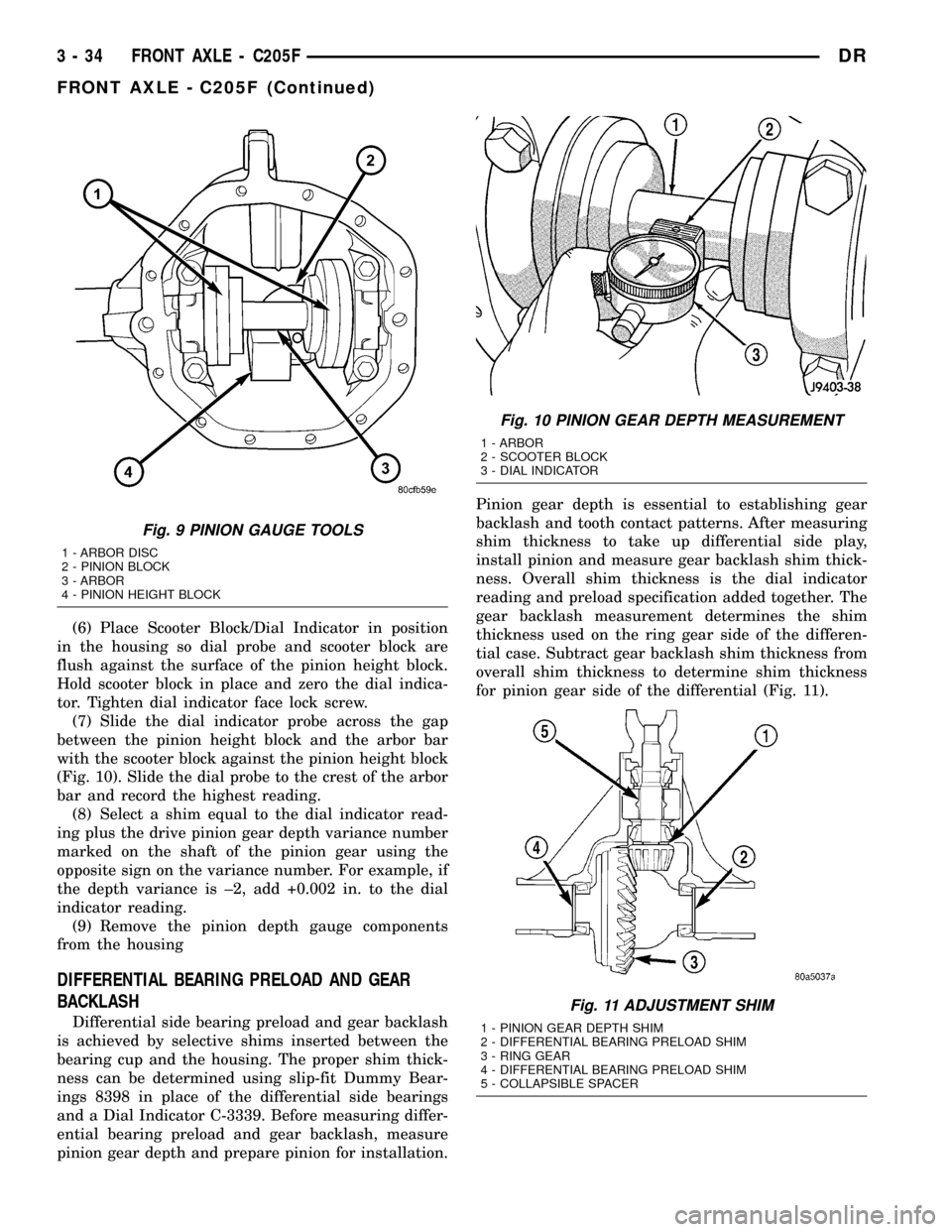
(6) Place Scooter Block/Dial Indicator in position
in the housing so dial probe and scooter block are
flush against the surface of the pinion height block.
Hold scooter block in place and zero the dial indica-
tor. Tighten dial indicator face lock screw.
(7) Slide the dial indicator probe across the gap
between the pinion height block and the arbor bar
with the scooter block against the pinion height block
(Fig. 10). Slide the dial probe to the crest of the arbor
bar and record the highest reading.
(8) Select a shim equal to the dial indicator read-
ing plus the drive pinion gear depth variance number
marked on the shaft of the pinion gear using the
opposite sign on the variance number. For example, if
the depth variance is ±2, add +0.002 in. to the dial
indicator reading.
(9) Remove the pinion depth gauge components
from the housing
DIFFERENTIAL BEARING PRELOAD AND GEAR
BACKLASH
Differential side bearing preload and gear backlash
is achieved by selective shims inserted between the
bearing cup and the housing. The proper shim thick-
ness can be determined using slip-fit Dummy Bear-
ings 8398 in place of the differential side bearings
and a Dial Indicator C-3339. Before measuring differ-
ential bearing preload and gear backlash, measure
pinion gear depth and prepare pinion for installation.Pinion gear depth is essential to establishing gear
backlash and tooth contact patterns. After measuring
shim thickness to take up differential side play,
install pinion and measure gear backlash shim thick-
ness. Overall shim thickness is the dial indicator
reading and preload specification added together. The
gear backlash measurement determines the shim
thickness used on the ring gear side of the differen-
tial case. Subtract gear backlash shim thickness from
overall shim thickness to determine shim thickness
for pinion gear side of the differential (Fig. 11).
Fig. 9 PINION GAUGE TOOLS
1 - ARBOR DISC
2 - PINION BLOCK
3 - ARBOR
4 - PINION HEIGHT BLOCK
Fig. 10 PINION GEAR DEPTH MEASUREMENT
1 - ARBOR
2 - SCOOTER BLOCK
3 - DIAL INDICATOR
Fig. 11 ADJUSTMENT SHIM
1 - PINION GEAR DEPTH SHIM
2 - DIFFERENTIAL BEARING PRELOAD SHIM
3 - RING GEAR
4 - DIFFERENTIAL BEARING PRELOAD SHIM
5 - COLLAPSIBLE SPACER
3 - 34 FRONT AXLE - C205FDR
FRONT AXLE - C205F (Continued)
Page 130 of 2627
PINION GEAR/RING GEAR
REMOVAL
NOTE: The ring gear and pinion are serviced in a
matched set. Never replace one without replacing
the other.
(1) Remove differential from housing.
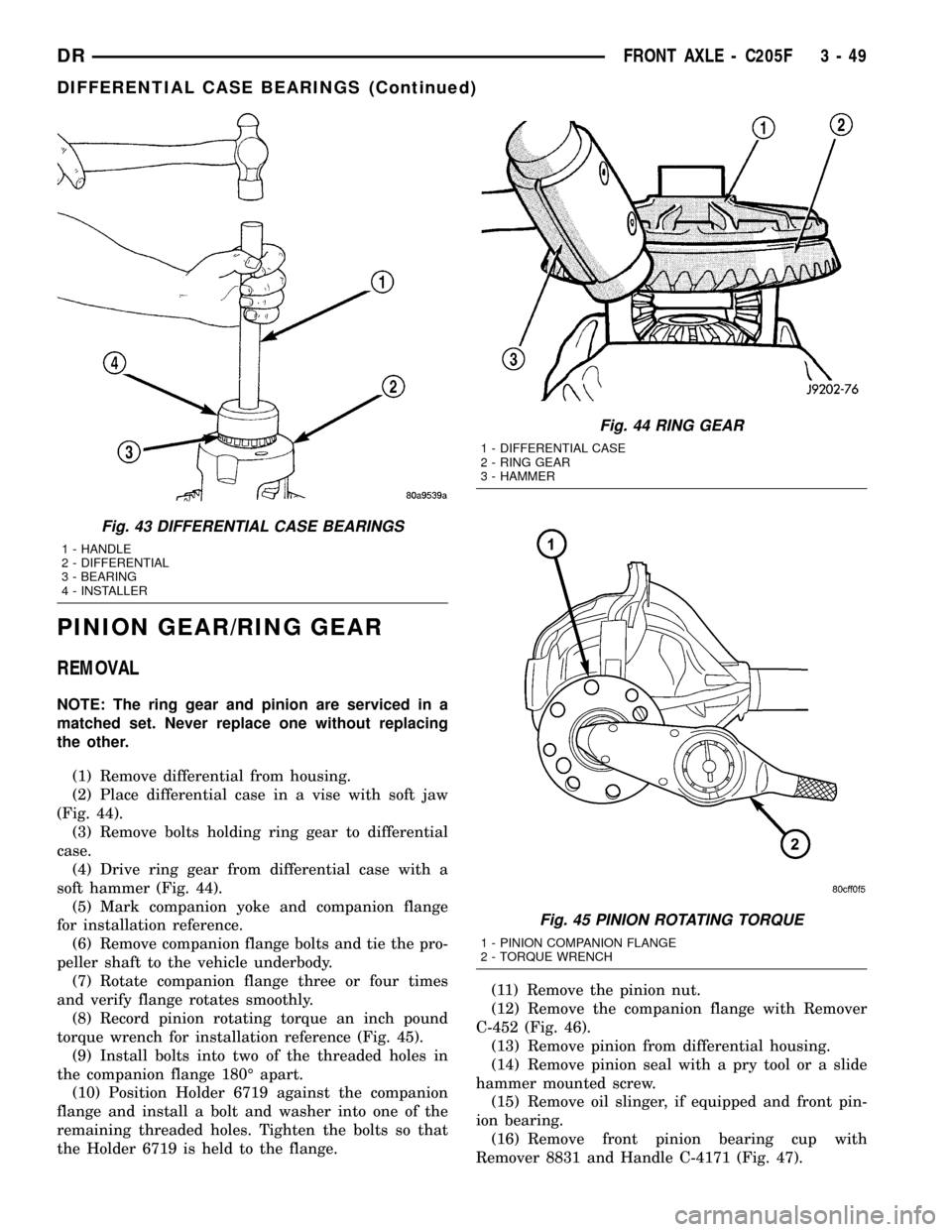
(2) Place differential case in a vise with soft jaw
(Fig. 44).
(3) Remove bolts holding ring gear to differential
case.
(4) Drive ring gear from differential case with a
soft hammer (Fig. 44).
(5) Mark companion yoke and companion flange
for installation reference.
(6) Remove companion flange bolts and tie the pro-
peller shaft to the vehicle underbody.
(7) Rotate companion flange three or four times
and verify flange rotates smoothly.
(8) Record pinion rotating torque an inch pound
torque wrench for installation reference (Fig. 45).
(9) Install bolts into two of the threaded holes in
the companion flange 180É apart.
(10) Position Holder 6719 against the companion
flange and install a bolt and washer into one of the
remaining threaded holes. Tighten the bolts so that
the Holder 6719 is held to the flange.(11) Remove the pinion nut.
(12) Remove the companion flange with Remover
C-452 (Fig. 46).
(13) Remove pinion from differential housing.
(14) Remove pinion seal with a pry tool or a slide
hammer mounted screw.
(15) Remove oil slinger, if equipped and front pin-
ion bearing.
(16) Remove front pinion bearing cup with
Remover 8831 and Handle C-4171 (Fig. 47).
Fig. 43 DIFFERENTIAL CASE BEARINGS
1 - HANDLE
2 - DIFFERENTIAL
3 - BEARING
4 - INSTALLER
Fig. 44 RING GEAR
1 - DIFFERENTIAL CASE
2 - RING GEAR
3 - HAMMER
Fig. 45 PINION ROTATING TORQUE
1 - PINION COMPANION FLANGE
2 - TORQUE WRENCH
DRFRONT AXLE - C205F 3 - 49
DIFFERENTIAL CASE BEARINGS (Continued)
Page 136 of 2627
VIBRATION
Vibration at the front/rear of the vehicle is usually
caused by:
²Damaged drive shaft.
²Missing drive shaft balance weight(s).
²Worn or out of balance wheels.
²Loose wheel lug nuts.
²Worn U-joint(s).
²Loose/broken springs.
²Damaged axle shaft bearing(s).
²Loose pinion gear nut.
²Excessive pinion yoke run out.
²Bent axle shaft(s).
Check for loose or damaged front end components
or engine/transmission mounts. These components
can contribute to what appears to be a vibration. Do
not overlook engine accessories, brackets and drive
belts.
DRIVELINE SNAP
A snap or clunk noise when the vehicle is shifted
into gear (or the clutch engaged) can be caused by:
²High engine idle speed.
²Transmission shift operation.
²Loose engine/transmission/transfer case mounts.
²Worn U-joints.
²Loose spring mounts.
²Loose pinion gear nut and yoke.
²Excessive ring gear backlash.
²Excessive side gear to case clearance.
The source of a snap or a clunk noise can be deter-
mined with the assistance of a helper. Raise the vehi-
cle on a hoist with the wheels free to rotate. Instruct
the helper to shift the transmission into gear and lis-
ten for the noise. A mechanics stethoscope is helpful
in isolating the source of a noise.
DIAGNOSTIC CHART
Condition Possible Causes Correction
Wheel Noise 1. Wheel loose. 1. Tighten loose nuts.
2. Faulty, brinelled wheel bearing. 2. Replace bearing.
Axle Shaft Noise 1. Misaligned axle tube. 1. Inspect axle tube alignment.
Correct as necessary.
2. Bent or sprung axle shaft. 2. Inspect and correct as necessary.
3. End-play in pinion bearings. 3. Refer to pinion pre-load
information and correct as
necessary.
4. Excessive gear backlash
between the ring gear and pinion.4. Check adjustment of the ring
gear and pinion backlash. Correct
as necessary.
5. Improper adjustment of pinion
gear bearings.5. Adjust the pinion bearings
pre-load.
6. Loose pinion yoke nut. 6. Tighten the pinion yoke nut.
7. Scuffed gear tooth contact
surfaces.7. Inspect and replace as
necessary.
Axle Shaft Broke 1. Misaligned axle tube. 1. Replace the broken shaft after
correcting tube mis-alignment.
2 Vehicle overloaded. 2. Replace broken shaft and avoid
excessive weight on vehicle.
3. Erratic clutch operation. 3. Replace broken shaft and avoid
or correct erratic clutch operation.
4. Grabbing clutch. 4. Replace broken shaft and inspect
and repair clutch as necessary.
DRFRONT AXLE - 9 1/4 AA 3 - 55
FRONT AXLE - 9 1/4 AA (Continued)
Page 149 of 2627
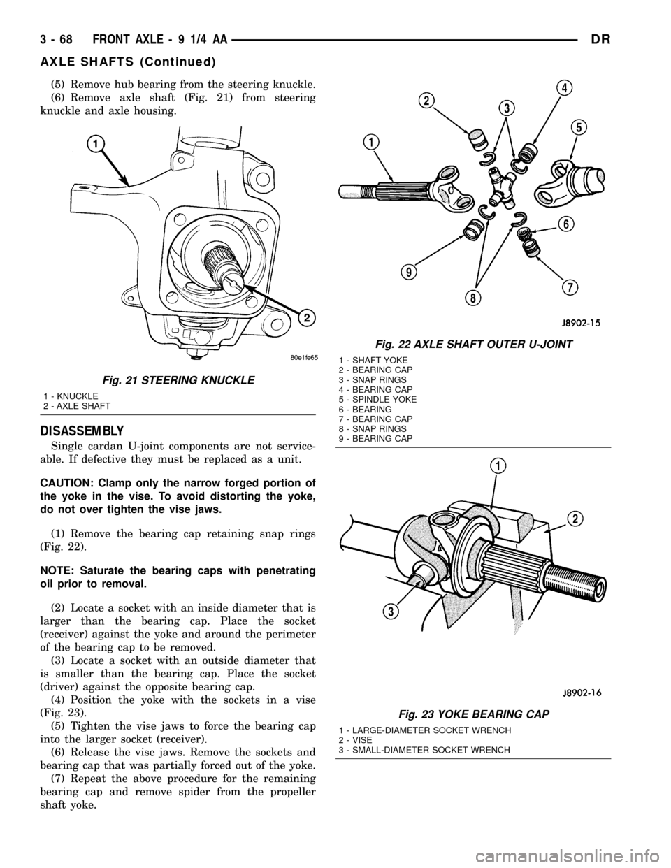
(5) Remove hub bearing from the steering knuckle.
(6) Remove axle shaft (Fig. 21) from steering
knuckle and axle housing.
DISASSEMBLY
Single cardan U-joint components are not service-
able. If defective they must be replaced as a unit.
CAUTION: Clamp only the narrow forged portion of
the yoke in the vise. To avoid distorting the yoke,
do not over tighten the vise jaws.
(1) Remove the bearing cap retaining snap rings
(Fig. 22).
NOTE: Saturate the bearing caps with penetrating
oil prior to removal.
(2) Locate a socket with an inside diameter that is
larger than the bearing cap. Place the socket
(receiver) against the yoke and around the perimeter
of the bearing cap to be removed.
(3) Locate a socket with an outside diameter that
is smaller than the bearing cap. Place the socket
(driver) against the opposite bearing cap.
(4) Position the yoke with the sockets in a vise
(Fig. 23).
(5) Tighten the vise jaws to force the bearing cap
into the larger socket (receiver).
(6) Release the vise jaws. Remove the sockets and
bearing cap that was partially forced out of the yoke.
(7) Repeat the above procedure for the remaining
bearing cap and remove spider from the propeller
shaft yoke.
Fig. 21 STEERING KNUCKLE
1 - KNUCKLE
2 - AXLE SHAFT
Fig. 22 AXLE SHAFT OUTER U-JOINT
1 - SHAFT YOKE
2 - BEARING CAP
3 - SNAP RINGS
4 - BEARING CAP
5 - SPINDLE YOKE
6 - BEARING
7 - BEARING CAP
8 - SNAP RINGS
9 - BEARING CAP
Fig. 23 YOKE BEARING CAP
1 - LARGE-DIAMETER SOCKET WRENCH
2 - VISE
3 - SMALL-DIAMETER SOCKET WRENCH
3 - 68 FRONT AXLE - 9 1/4 AADR
AXLE SHAFTS (Continued)
Page 161 of 2627
REAR AXLE-91/4
TABLE OF CONTENTS
page page
REAR AXLE-91/4
DIAGNOSIS AND TESTING................80
REMOVAL.............................83
INSTALLATION.........................83
ADJUSTMENTS........................83
SPECIFICATIONS.......................90
SPECIAL TOOLS.......................90
AXLE SHAFTS
REMOVAL.............................93
INSTALLATION.........................94
AXLE SHAFT SEALS
REMOVAL.............................94
INSTALLATION.........................94
AXLE BEARINGS
REMOVAL.............................95
INSTALLATION.........................95
PINION SEAL
REMOVAL.............................95
INSTALLATION.........................96
DIFFERENTIAL COVER
REMOVAL.............................97INSTALLATION.........................97
DIFFERENTIAL
REMOVAL.............................97
DISASSEMBLY.........................98
ASSEMBLY............................99
INSTALLATION.........................99
DIFFERENTIAL-TRAC-LOK
DESCRIPTION........................100
OPERATION..........................100
DIAGNOSIS AND TESTING...............100
DISASSEMBLY........................101
ASSEMBLY...........................103
DIFFERENTIAL CASE BEARINGS
REMOVAL............................105
INSTALLATION........................106
PINION GEAR/RING GEAR/TONE RING
REMOVAL............................106
INSTALLATION........................108
REAR AXLE-91/4
DIAGNOSIS AND TESTING
GEAR NOISE
Axle gear noise can be caused by insufficient lubri-
cant, incorrect backlash, incorrect pinion depth, tooth
contact, worn/damaged gears, or the carrier housing
not having the proper offset and squareness.
Gear noise usually happens at a specific speed
range. The noise can also occur during a specific type
of driving condition. These conditions are accelera-
tion, deceleration, coast, or constant load.
When road testing, first warm-up the axle fluid by
driving the vehicle at least 5 miles and then acceler-
ate the vehicle to the speed range where the noise is
the greatest. Shift out-of-gear and coast through the
peak-noise range. If the noise stops or changes
greatly check for:
²Insufficient lubricant.
²Incorrect ring gear backlash.
²Gear damage.
Differential side gears and pinions can be checked
by turning the vehicle. They usually do not cause
noise during straight-ahead driving when the gears
are unloaded. The side gears are loaded during vehi-cle turns. A worn pinion shaft can also cause a snap-
ping or a knocking noise.
BEARING NOISE
The axle shaft, differential and pinion bearings can
all produce noise when worn or damaged. Bearing
noise can be either a whining, or a growling sound.
Pinion bearingshave a constant-pitch noise. This
noise changes only with vehicle speed. Pinion bearing
noise will be higher pitched because it rotates at a
faster rate. Drive the vehicle and load the differen-
tial. If bearing noise occurs, the rear pinion bearing
is the source of the noise. If the bearing noise is
heard during a coast, the front pinion bearing is the
source.
Differential bearingsusually produce a low pitch
noise. Differential bearing noise is similar to pinion
bearing noise. The pitch of differential bearing noise
is also constant and varies only with vehicle speed.
Axle shaft bearingsproduce noise and vibration
when worn or damaged. The noise generally changes
when the bearings are loaded. Road test the vehicle.
Turn the vehicle sharply to the left and to the right.
This will load the bearings and change the noise
level. Where axle bearing damage is slight, the noise
is usually not noticeable at speeds above 30 mph.
3 - 80 REAR AXLE-91/4DR
Page 162 of 2627
LOW SPEED KNOCK
Low speed knock is generally caused by:
²Worn U-joint.
²Worn side gear thrust washers.
²Worn pinion shaft bore.
VIBRATION
Vibration at the rear of the vehicle is usually
caused by a:
²Damaged drive shaft.
²Missing drive shaft balance weight(s).
²Worn or out-of-balance wheels.
²Loose wheel lug nuts.
²Worn U-joint(s).
²Loose/broken springs.
²Damaged axle shaft bearing(s).
²Loose pinion gear nut.
²Excessive pinion yoke run out.
²Bent axle shaft(s).
Check for loose or damaged front-end components
or engine/transmission mounts. These components
can contribute to what appears to be a rearend vibra-
tion. Do not overlook engine accessories, brackets
and drive belts.NOTE: All driveline components should be exam-
ined before starting any repair.
DRIVELINE SNAP
A snap or clunk noise when the vehicle is shifted
into gear (or the clutch engaged), can be caused by:
²High engine idle speed.
²Transmission shift operation.
²Loose engine/transmission/transfer case mounts.
²Worn U-joints.
²Loose spring mounts.
²Loose pinion gear nut and yoke.
²Excessive ring gear backlash.
²Excessive side gear to case clearance.
The source of a snap or a clunk noise can be deter-
mined with the assistance of a helper. Raise the vehi-
cle on a hoist with the wheels free to rotate. Instruct
the helper to shift the transmission into gear. Listen
for the noise, a mechanics stethoscope is helpful in
isolating the source of a noise.
DIAGNOSTIC CHART
Condition Possible Causes Correction
Wheel Noise 1. Wheel loose. 1. Tighten loose nuts.
2. Faulty, brinelled wheel bearing. 2. Replace bearing.
Axle Shaft Noise 1. Misaligned axle tube. 1. Inspect axle tube alignment.
Correct as necessary.
2. Bent or sprung axle shaft. 2. Inspect and correct as necessary.
Axle Shaft Broke 1. Misaligned axle tube. 1. Replace the broken shaft after
correcting tube mis-alignment.
2 Vehicle overloaded. 2. Replace broken shaft and avoid
excessive weight on vehicle.
3. Erratic clutch operation. 3. Replace broken shaft and avoid
or correct erratic clutch operation.
4. Grabbing clutch. 4. Replace broken shaft and inspect
and repair clutch as necessary.
DRREAR AXLE - 9 1/4 3 - 81
REAR AXLE - 9 1/4 (Continued)
Page 176 of 2627
(3) Install the axle shaft.
(4) Install differential cover and fill with gear
lubricant to the bottom of the fill plug hole.
AXLE BEARINGS
REMOVAL
(1) Remove axle shaft.
(2) Remove axle shaft seal from axle tube with a
small pry bar.
NOTE: The seal and bearing can be removed at the
same time with the bearing removal tool.
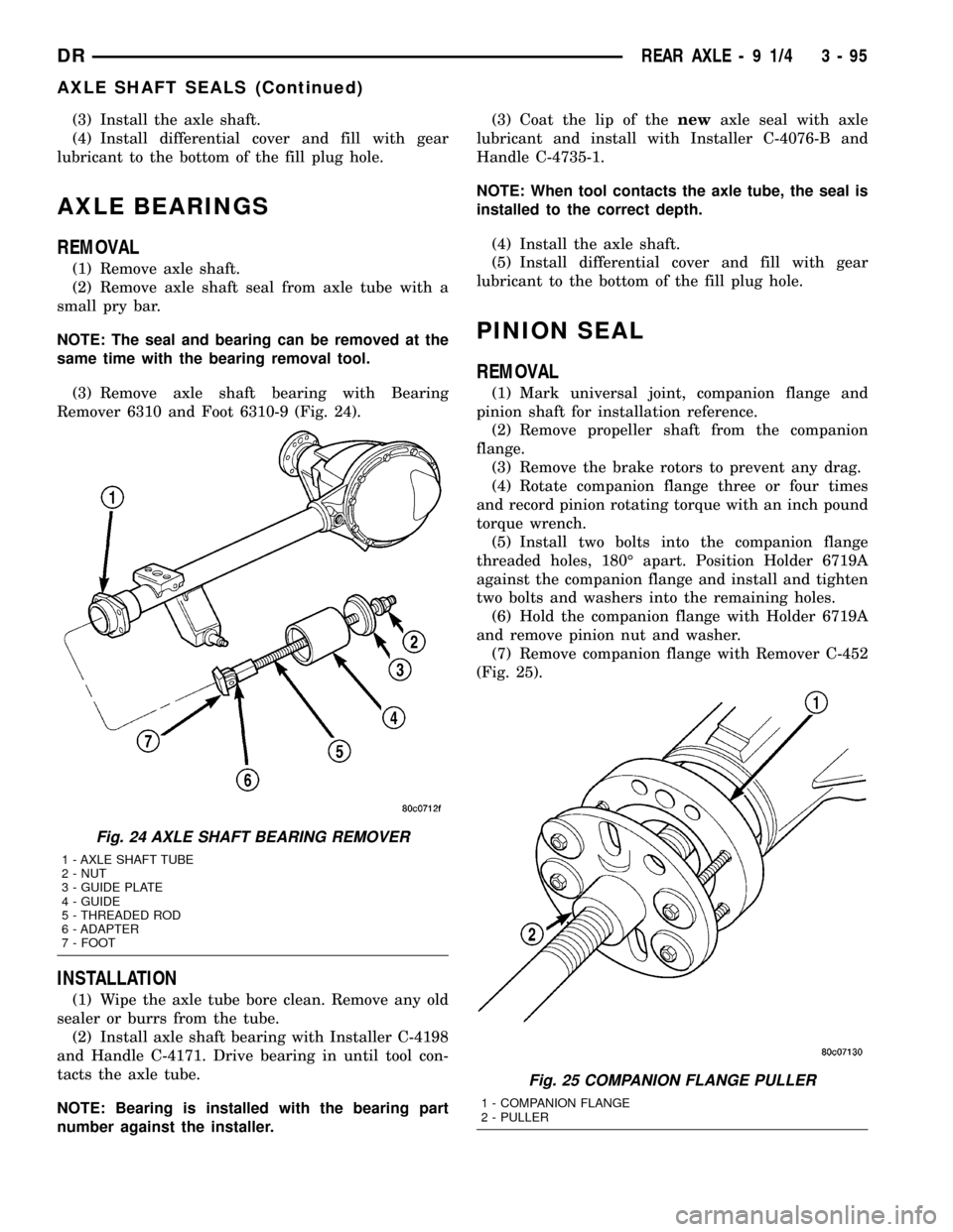
(3) Remove axle shaft bearing with Bearing
Remover 6310 and Foot 6310-9 (Fig. 24).
INSTALLATION
(1) Wipe the axle tube bore clean. Remove any old
sealer or burrs from the tube.
(2) Install axle shaft bearing with Installer C-4198
and Handle C-4171. Drive bearing in until tool con-
tacts the axle tube.
NOTE: Bearing is installed with the bearing part
number against the installer.(3) Coat the lip of thenewaxle seal with axle
lubricant and install with Installer C-4076-B and
Handle C-4735-1.
NOTE: When tool contacts the axle tube, the seal is
installed to the correct depth.
(4) Install the axle shaft.
(5) Install differential cover and fill with gear
lubricant to the bottom of the fill plug hole.
PINION SEAL
REMOVAL
(1) Mark universal joint, companion flange and
pinion shaft for installation reference.
(2) Remove propeller shaft from the companion
flange.
(3) Remove the brake rotors to prevent any drag.
(4) Rotate companion flange three or four times
and record pinion rotating torque with an inch pound
torque wrench.
(5) Install two bolts into the companion flange
threaded holes, 180É apart. Position Holder 6719A
against the companion flange and install and tighten
two bolts and washers into the remaining holes.
(6) Hold the companion flange with Holder 6719A
and remove pinion nut and washer.
(7) Remove companion flange with Remover C-452
(Fig. 25).
Fig. 24 AXLE SHAFT BEARING REMOVER
1 - AXLE SHAFT TUBE
2 - NUT
3 - GUIDE PLATE
4 - GUIDE
5 - THREADED ROD
6 - ADAPTER
7 - FOOT
Fig. 25 COMPANION FLANGE PULLER
1 - COMPANION FLANGE
2 - PULLER
DRREAR AXLE - 9 1/4 3 - 95
AXLE SHAFT SEALS (Continued)
Page 181 of 2627
CAUTION: If cover is not installed within 3 to 5 min-
utes, the cover must be cleaned and new RTV
applied or adhesion quality will be compromised.
(8) Install the cover and any identification tag and
tighten cover bolts to 41 N´m (30 ft. lbs.).
(9) Fill differential with lubricant to bottom of the
fill plug hole. Refer to the Lubricant Specifications
for the correct quantity and type.
NOTE: Trac-lokŸ differential equipped vehicles
should be road tested by making 10 to 12 slow fig-
ure-eight turns. This maneuver will pump the lubri-
cant through the clutch discs to eliminate a
possible chatter noise complaint.
DIFFERENTIAL-TRAC-LOK
DESCRIPTION
The optional Trac-Loktdifferential case has a one-
piece design and the similar internal components as
a standard differential, plus two clutch disc pack-
s.The differential pinion mate shaft is retained with
a threaded pin. Differential bearing preload and ring
gear backlash are set and maintained by threaded
adjusters at the outside of the differential housing.
Pinion bearing preload is set and maintained by the
use of a collapsible spacer. The removable differential
cover provides a means for inspection and service.
OPERATION
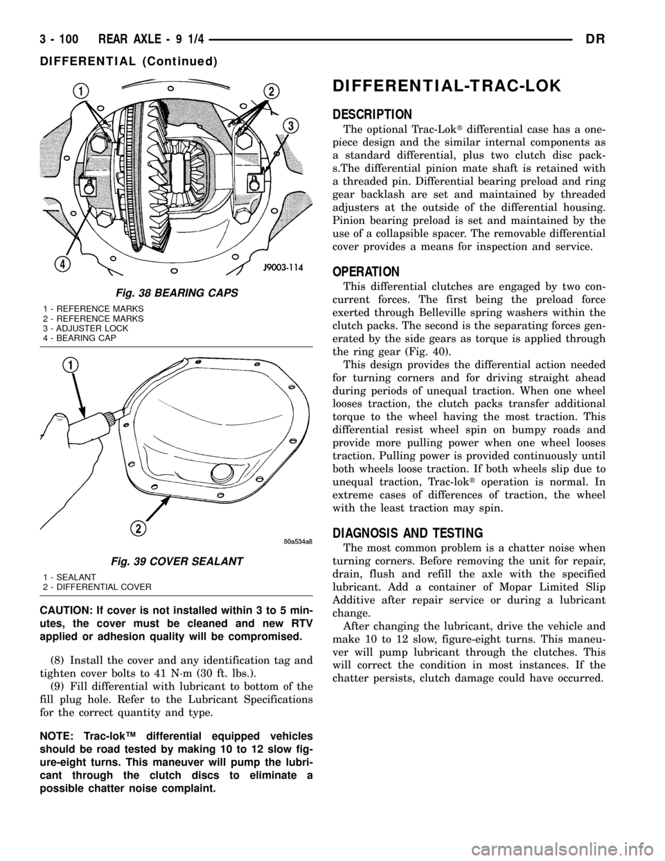
This differential clutches are engaged by two con-
current forces. The first being the preload force
exerted through Belleville spring washers within the
clutch packs. The second is the separating forces gen-
erated by the side gears as torque is applied through
the ring gear (Fig. 40).
This design provides the differential action needed
for turning corners and for driving straight ahead
during periods of unequal traction. When one wheel
looses traction, the clutch packs transfer additional
torque to the wheel having the most traction. This
differential resist wheel spin on bumpy roads and
provide more pulling power when one wheel looses
traction. Pulling power is provided continuously until
both wheels loose traction. If both wheels slip due to
unequal traction, Trac-loktoperation is normal. In
extreme cases of differences of traction, the wheel
with the least traction may spin.
DIAGNOSIS AND TESTING
The most common problem is a chatter noise when
turning corners. Before removing the unit for repair,
drain, flush and refill the axle with the specified
lubricant. Add a container of Mopar Limited Slip
Additive after repair service or during a lubricant
change.
After changing the lubricant, drive the vehicle and
make 10 to 12 slow, figure-eight turns. This maneu-
ver will pump lubricant through the clutches. This
will correct the condition in most instances. If the
chatter persists, clutch damage could have occurred.
Fig. 38 BEARING CAPS
1 - REFERENCE MARKS
2 - REFERENCE MARKS
3 - ADJUSTER LOCK
4 - BEARING CAP
Fig. 39 COVER SEALANT
1 - SEALANT
2 - DIFFERENTIAL COVER
3 - 100 REAR AXLE-91/4DR
DIFFERENTIAL (Continued)
Page 187 of 2627
INSTALLATION
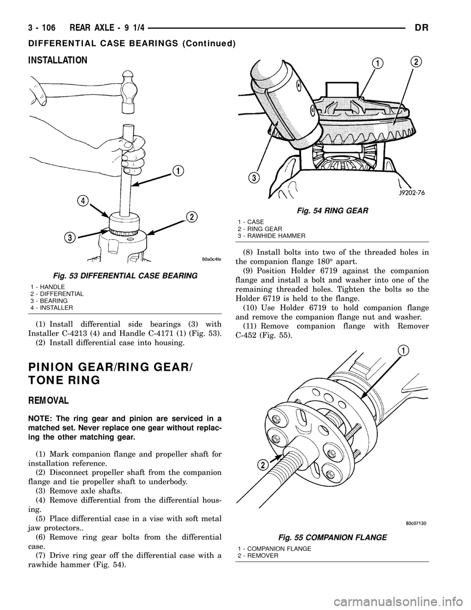
(1) Install differential side bearings (3) with
Installer C-4213 (4) and Handle C-4171 (1) (Fig. 53).
(2) Install differential case into housing.
PINION GEAR/RING GEAR/
TONE RING
REMOVAL
NOTE: The ring gear and pinion are serviced in a
matched set. Never replace one gear without replac-
ing the other matching gear.
(1) Mark companion flange and propeller shaft for
installation reference.
(2) Disconnect propeller shaft from the companion
flange and tie propeller shaft to underbody.
(3) Remove axle shafts.
(4) Remove differential from the differential hous-
ing.
(5) Place differential case in a vise with soft metal
jaw protectors..
(6) Remove ring gear bolts from the differential
case.
(7) Drive ring gear off the differential case with a
rawhide hammer (Fig. 54).(8) Install bolts into two of the threaded holes in
the companion flange 180É apart.
(9) Position Holder 6719 against the companion
flange and install a bolt and washer into one of the
remaining threaded holes. Tighten the bolts so the
Holder 6719 is held to the flange.
(10) Use Holder 6719 to hold companion flange
and remove the companion flange nut and washer.
(11) Remove companion flange with Remover
C-452 (Fig. 55).
Fig. 53 DIFFERENTIAL CASE BEARING
1 - HANDLE
2 - DIFFERENTIAL
3 - BEARING
4 - INSTALLER
Fig. 54 RING GEAR
1 - CASE
2 - RING GEAR
3 - RAWHIDE HAMMER
Fig. 55 COMPANION FLANGE
1 - COMPANION FLANGE
2 - REMOVER
3 - 106 REAR AXLE-91/4DR
DIFFERENTIAL CASE BEARINGS (Continued)
Page 188 of 2627
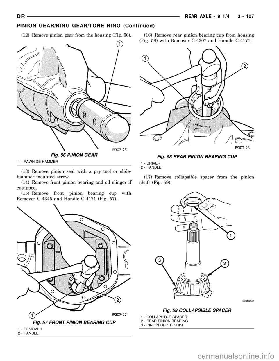
(12)Remove pinion gear from the housing (Fig. 56).
(13) Remove pinion seal with a pry tool or slide-
hammer mounted screw.
(14) Remove front pinion bearing and oil slinger if
equipped.
(15) Remove front pinion bearing cup with
Remover C-4345 and Handle C-4171 (Fig. 57).(16) Remove rear pinion bearing cup from housing
(Fig. 58) with Remover C-4307 and Handle C-4171.
(17) Remove collapsible spacer from the pinion
shaft (Fig. 59).
Fig. 56 PINION GEAR
1 - RAWHIDE HAMMER
Fig. 57 FRONT PINION BEARING CUP
1 - REMOVER
2 - HANDLE
Fig. 58 REAR PINION BEARING CUP
1 - DRIVER
2 - HANDLE
Fig. 59 COLLAPSIBLE SPACER
1 - COLLAPSIBLE SPACER
2 - REAR PINION BEARING
3 - PINION DEPTH SHIM
DRREAR AXLE - 9 1/4 3 - 107
PINION GEAR/RING GEAR/TONE RING (Continued)