Sensor DODGE RAM 1500 1998 2.G User Guide
[x] Cancel search | Manufacturer: DODGE, Model Year: 1998, Model line: RAM 1500, Model: DODGE RAM 1500 1998 2.GPages: 2627
Page 66 of 2627
HUB / BEARING
REMOVAL
(1) Raise and support the vehicle.
(2) Remove the wheel and tire assembly.
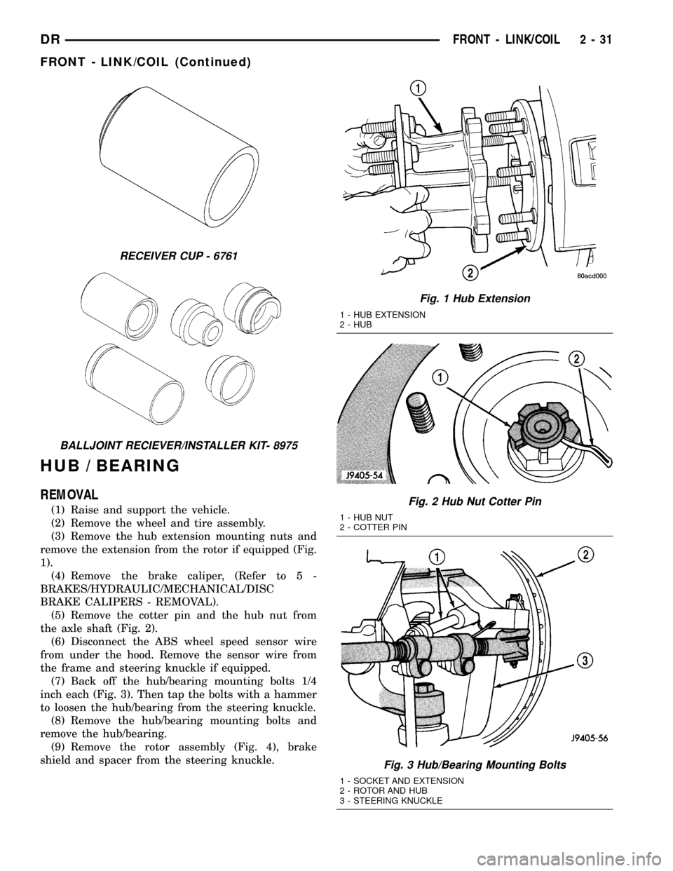
(3) Remove the hub extension mounting nuts and
remove the extension from the rotor if equipped (Fig.
1).
(4) Remove the brake caliper, (Refer to 5 -
BRAKES/HYDRAULIC/MECHANICAL/DISC
BRAKE CALIPERS - REMOVAL).
(5) Remove the cotter pin and the hub nut from
the axle shaft (Fig. 2).
(6) Disconnect the ABS wheel speed sensor wire
from under the hood. Remove the sensor wire from
the frame and steering knuckle if equipped.
(7) Back off the hub/bearing mounting bolts 1/4
inch each (Fig. 3). Then tap the bolts with a hammer
to loosen the hub/bearing from the steering knuckle.
(8) Remove the hub/bearing mounting bolts and
remove the hub/bearing.
(9) Remove the rotor assembly (Fig. 4), brake
shield and spacer from the steering knuckle.
RECEIVER CUP - 6761
BALLJOINT RECIEVER/INSTALLER KIT- 8975
Fig. 1 Hub Extension
1 - HUB EXTENSION
2 - HUB
Fig. 2 Hub Nut Cotter Pin
1 - HUB NUT
2 - COTTER PIN
Fig. 3 Hub/Bearing Mounting Bolts
1 - SOCKET AND EXTENSION
2 - ROTOR AND HUB
3 - STEERING KNUCKLE
DRFRONT - LINK/COIL 2 - 31
FRONT - LINK/COIL (Continued)
Page 67 of 2627
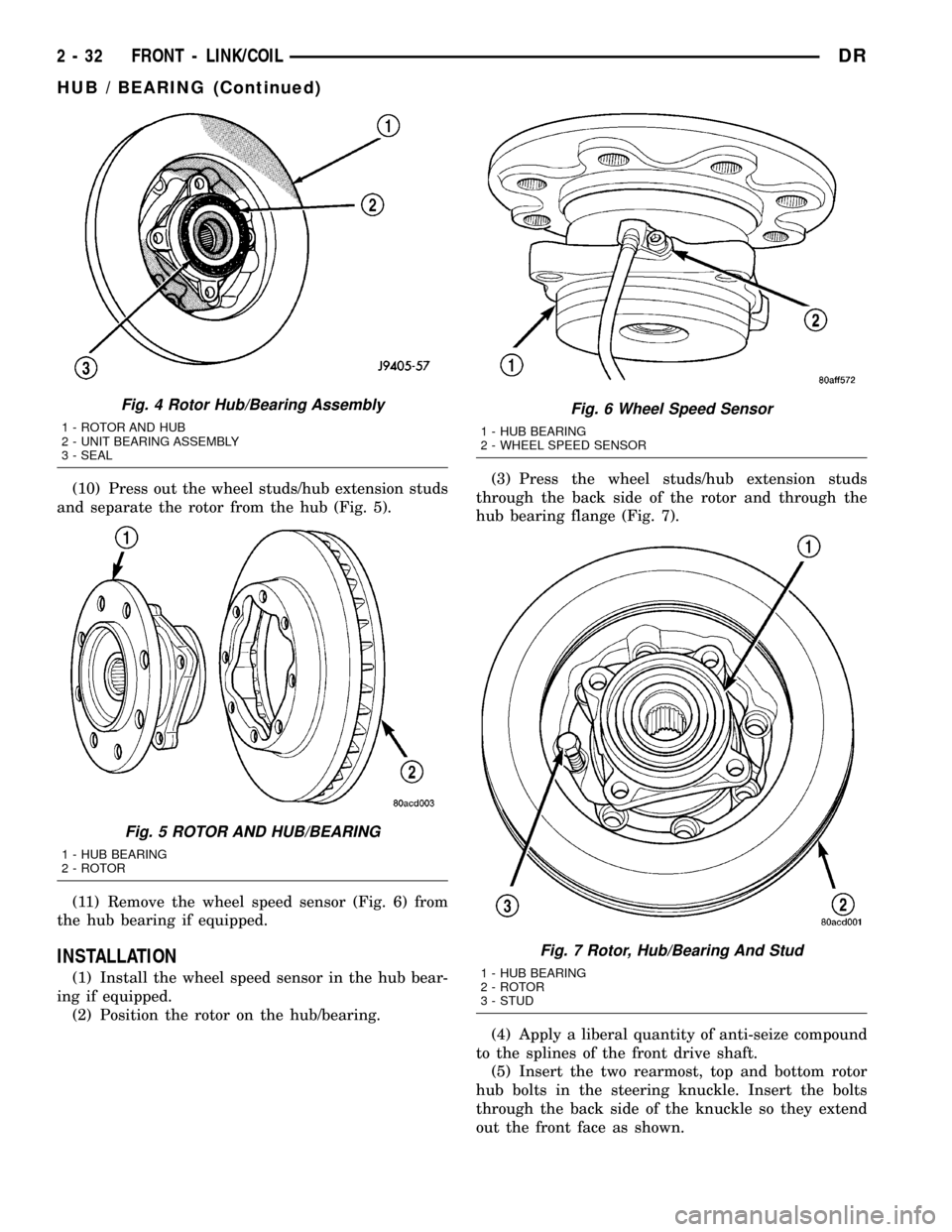
(10) Press out the wheel studs/hub extension studs
and separate the rotor from the hub (Fig. 5).
(11) Remove the wheel speed sensor (Fig. 6) from
the hub bearing if equipped.
INSTALLATION
(1) Install the wheel speed sensor in the hub bear-
ing if equipped.
(2) Position the rotor on the hub/bearing.(3) Press the wheel studs/hub extension studs
through the back side of the rotor and through the
hub bearing flange (Fig. 7).
(4) Apply a liberal quantity of anti-seize compound
to the splines of the front drive shaft.
(5) Insert the two rearmost, top and bottom rotor
hub bolts in the steering knuckle. Insert the bolts
through the back side of the knuckle so they extend
out the front face as shown.
Fig. 4 Rotor Hub/Bearing Assembly
1 - ROTOR AND HUB
2 - UNIT BEARING ASSEMBLY
3 - SEAL
Fig. 5 ROTOR AND HUB/BEARING
1 - HUB BEARING
2 - ROTOR
Fig. 6 Wheel Speed Sensor
1 - HUB BEARING
2 - WHEEL SPEED SENSOR
Fig. 7 Rotor, Hub/Bearing And Stud
1 - HUB BEARING
2 - ROTOR
3 - STUD
2 - 32 FRONT - LINK/COILDR
HUB / BEARING (Continued)
Page 68 of 2627
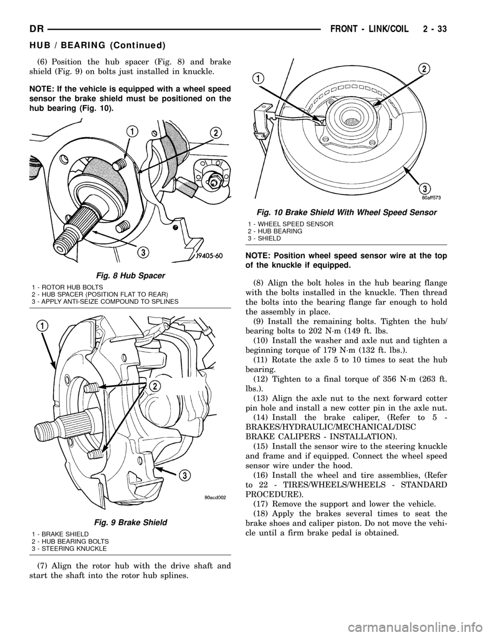
(6) Position the hub spacer (Fig. 8) and brake
shield (Fig. 9) on bolts just installed in knuckle.
NOTE: If the vehicle is equipped with a wheel speed
sensor the brake shield must be positioned on the
hub bearing (Fig. 10).
(7) Align the rotor hub with the drive shaft and
start the shaft into the rotor hub splines.NOTE: Position wheel speed sensor wire at the top
of the knuckle if equipped.
(8) Align the bolt holes in the hub bearing flange
with the bolts installed in the knuckle. Then thread
the bolts into the bearing flange far enough to hold
the assembly in place.
(9) Install the remaining bolts. Tighten the hub/
bearing bolts to 202 N´m (149 ft. lbs.
(10) Install the washer and axle nut and tighten a
beginning torque of 179 N´m (132 ft. lbs.).
(11) Rotate the axle 5 to 10 times to seat the hub
bearing.
(12) Tighten to a final torque of 356 N´m (263 ft.
lbs.).
(13) Align the axle nut to the next forward cotter
pin hole and install a new cotter pin in the axle nut.
(14) Install the brake caliper, (Refer to 5 -
BRAKES/HYDRAULIC/MECHANICAL/DISC
BRAKE CALIPERS - INSTALLATION).
(15) Install the sensor wire to the steering knuckle
and frame and if equipped. Connect the wheel speed
sensor wire under the hood.
(16) Install the wheel and tire assemblies, (Refer
to 22 - TIRES/WHEELS/WHEELS - STANDARD
PROCEDURE).
(17) Remove the support and lower the vehicle.
(18) Apply the brakes several times to seat the
brake shoes and caliper piston. Do not move the vehi-
cle until a firm brake pedal is obtained.
Fig. 8 Hub Spacer
1 - ROTOR HUB BOLTS
2 - HUB SPACER (POSITION FLAT TO REAR)
3 - APPLY ANTI-SEIZE COMPOUND TO SPLINES
Fig. 9 Brake Shield
1 - BRAKE SHIELD
2 - HUB BEARING BOLTS
3 - STEERING KNUCKLE
Fig. 10 Brake Shield With Wheel Speed Sensor
1 - WHEEL SPEED SENSOR
2 - HUB BEARING
3 - SHIELD
DRFRONT - LINK/COIL 2 - 33
HUB / BEARING (Continued)
Page 72 of 2627
KNUCKLE
REMOVAL
(1) Remove the hub bearing (Refer to 2 - SUSPEN-
SION/FRONT/HUB / BEARING - REMOVAL).
(2) Remove tie-rod or drag link end from the steer-
ing knuckle arm.
(3) Remove the ABS sensor wire and bracket from
knuckle. Refer to Brakes, for proper procedures.
(4) Remove the cotter pin from the upper ball stud
nut. Remove the upper and lower ball stud nuts.
(5) Strike the steering knuckle with a brass ham-
mer to loosen.
(6) Remove knuckle from axle tube yokes.
INSTALLATION
(1) Position the steering knuckle on the ball studs.
(2) Install and tighten lower ball stud nut to 47
N´m (35 ft. lbs.) torque. Do not install cotter pin at
this time.
(3) Install and tighten upper ball stud nut to 94
N´m (70 ft. lbs.) torque. Advance nut to next slot to
line up hole and install new cotter pin.
(4) Retorque lower ball stud nut to 190±217 N´m
(140±160 ft. lbs.) torque. Advance nut to next slot to
line up hole and install new cotter pin.
(5) Install the hub bearing (Refer to 2 - SUSPEN-
SION/FRONT/HUB / BEARING - INSTALLATION).
(6) Install tie-rod or drag link end onto the steer-
ing knuckle arm.
(7) Install the ABS sensor wire and bracket to the
knuckle. Refer to Brakes, for proper procedure.
UPPER SUSPENSION ARM
REMOVAL
REMOVAL - LEFT
(1) Raise and support the vehicle.
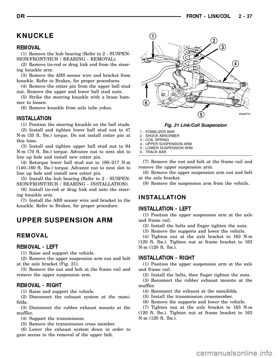
(2) Remove the upper suspension arm nut and bolt
at the axle bracket (Fig. 21).
(3) Remove the nut and bolt at the frame rail and
remove the upper suspension arm.
REMOVAL - RIGHT
(1) Raise and support the vehicle.
(2) Disconnect the exhaust system at the mani-
folds.
(3) Disconnect the rubber exhaust mounts at the
muffler.
(4) Support the transmission.
(5) Remove the transmission cross member.
(6) Lower the exhaust system down in order to
gain access to the removal of the upper bolt.(7) Remove the nut and bolt at the frame rail and
remove the upper suspension arm.
(8) Remove the upper suspension arm nut and bolt
at the axle bracket.
(9) Remove the suspension arm from the vehicle.
INSTALLATION
INSTALLATION - LEFT
(1) Position the upper suspension arm at the axle
and frame rail.
(2) Install the bolts and finger tighten the nuts.
(3) Remove the supports and lower the vehicle.
(4) Tighten nut at the axle bracket to 163 N´m
(120 ft. lbs.). Tighten nut at frame bracket to 163
N´m (120 ft. lbs.).
INSTALLATION - RIGHT
(1) Position the upper suspension arm at the axle
and frame rail.
(2) Install the bolts, then finger tighten the nuts.
(3) Reconnect the rubber exhaust mounts at the
muffler.
(4) Reconnect the exhaust at the manifolds.
(5) Install the transmission crossmember.
(6) Remove the supports and lower the vehicle.
(7) Tighten nut at the axle bracket to 163 N´m
(120 ft. lbs.). Tighten nut at frame bracket to 163
N´m (120 ft. lbs.).
Fig. 21 Link/Coil Suspension
1 - STABILIZER BAR
2 - SHOCK ABSORBER
3 - COIL SPRING
4 - UPPER SUSPENSION ARM
5 - LOWER SUSPENSION ARM
6 - TRACK BAR
DRFRONT - LINK/COIL 2 - 37
Page 138 of 2627
Condition Possible Causes Correction
Gear Teeth Broke 1. Overloading. 1. Replace gears. Examine other
gears and bearings for possible
damage.
2. Erratic clutch operation. 2. Replace gears and examine the
remaining parts for damage. Avoid
erratic clutch operation.
3. Ice-spotted pavement. 3. Replace gears and examine
remaining parts for damage.
4. Improper adjustments. 4. Replace gears and examine
remaining parts for damage. Ensure
ring gear backlash is correct.
Axle Noise 1. Insufficient lubricant. 1. Fill differential with the correct
fluid type and quantity.
2. Improper ring gear and pinion
adjustment.2. Check ring gear and pinion
contact pattern.
3. Unmatched ring gear and pinion. 3. Replace gears with a matched
ring gear and pinion.
4. Worn teeth on ring gear and/or
pinion.4. Replace ring gear and pinion.
5. Loose pinion bearings. 5. Adjust pinion bearing pre-load.
6. Loose differential bearings. 6. Adjust differential bearing
pre-load.
7. Mis-aligned or sprung ring gear. 7. Measure ring gear run-out.
Replace components as necessary.
8. Loose differential bearing cap
bolts.8. Inspect differential components
and replace as necessary. Ensure
that the bearing caps are torqued
tot he proper specification.
9. Housing not machined properly. 9. Replace housing.
REMOVAL
(1) With vehicle in neutral, position vehicle on
hoist.
(2) Remove brake calipers and rotors.
(3) Disconnect ABS wheel speed sensors.
(4) Disconnect axle vent hose.
(5) Remove front propeller shaft.
(6) Remove stabilizer bar links at the axle brack-
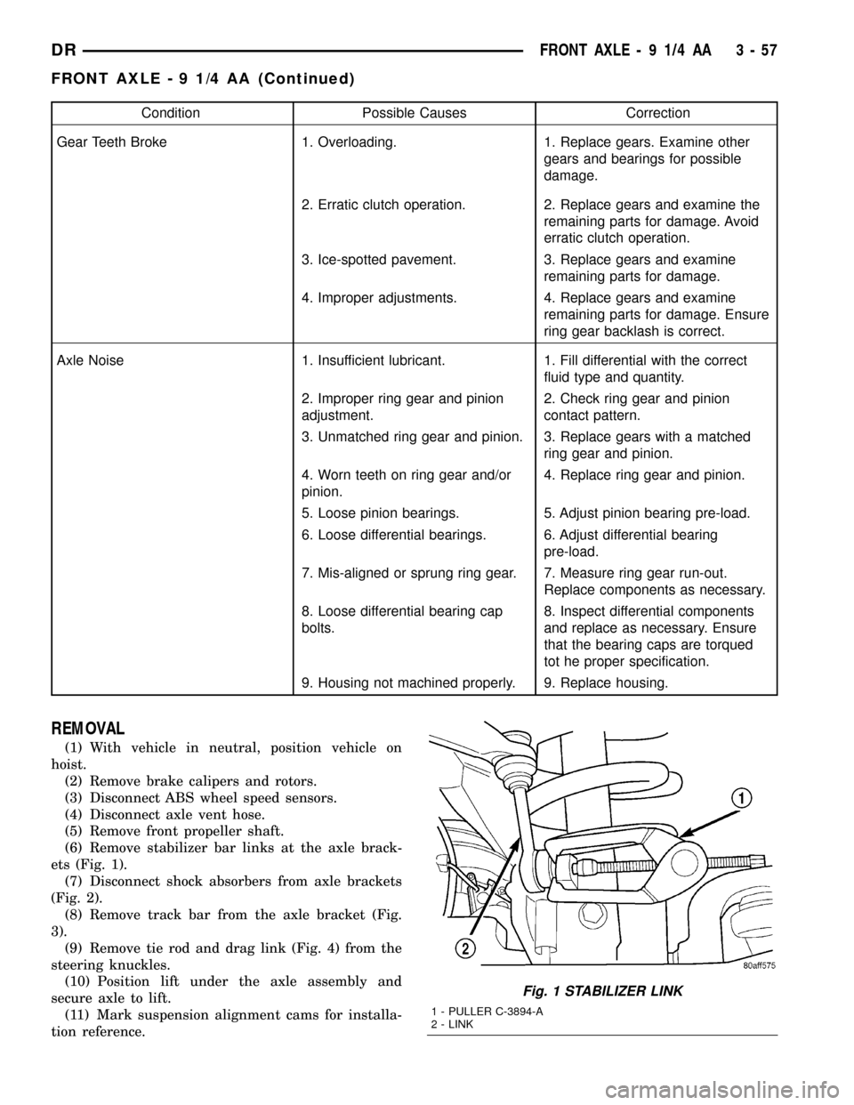
ets (Fig. 1).
(7) Disconnect shock absorbers from axle brackets
(Fig. 2).
(8) Remove track bar from the axle bracket (Fig.
3).
(9) Remove tie rod and drag link (Fig. 4) from the
steering knuckles.
(10) Position lift under the axle assembly and
secure axle to lift.
(11) Mark suspension alignment cams for installa-
tion reference.
Fig. 1 STABILIZER LINK
1 - PULLER C-3894-A
2 - LINK
DRFRONT AXLE - 9 1/4 AA 3 - 57
FRONT AXLE - 9 1/4 AA (Continued)
Page 140 of 2627
(7) Connect track bar to the axle bracket and
install the bolt. Do not tighten at this time.
(8) Install shock absorber and tighten bolts to 121
N´m (89 ft. lbs.).
(9) Install stabilizer bar link to the axle bracket.
Tighten the nut to 68 N´m (50 ft. lbs.).
(10) Install drag link and tie rod to the steering
knuckles and tighten the nuts to 108 N´m (80 ft.
lbs.).
(11) Install ABS wheel speed sensors.
(12) Install rotors and brake calipers.
(13) Connect the axle vent hose.
(14) Install front propeller shaft.
(15) With vehicle on the ground, tighten upper
suspension arm nuts at axle to 149 N´m (110 ft. lbs.).
Tighten upper suspension arm nuts at frame to 149
N´m (110 ft. lbs.).
(16) With vehicle on the ground, tighten lower sus-
pension arm nuts at axle to 190 N´m (140 ft. lbs.).
Tighten the lower suspension arm nuts at frame to
190 N´m (140 ft. lbs.).
(17) Tighten track bar bolt at the axle bracket to
176 N´m (130 ft. lbs.).
(18) Check front wheel alignment.
ADJUSTMENTS
Ring and pinion gears are supplied as matched
sets. Compensation for pinion depth variance is
achieved with a select shim. located between the rear
pinion bearing and pinion gear head.
PINION DEPTH MEASUREMENT AND ADJUSTMENT
Measurements are taken with pinion bearing cups
and pinion bearings installed in the housing. Take
measurements with Pinion Gauge Set and Dial Indi-
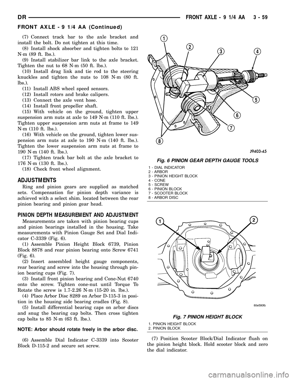
cator C-3339 (Fig. 6).
(1) Assemble Pinion Height Block 6739, Pinion
Block 8878 and rear pinion bearing onto Screw 6741
(Fig. 6).
(2) Insert assembled height gauge components,
rear bearing and screw into the housing through pin-
ion bearing cups (Fig. 7).
(3) Install front pinion bearing and Cone-Nut 6740
onto the screw. Tighten cone-nut until Torque To
Rotate the screw is 1.7-2.26 N´m (15-20 in. lbs.).
(4) Place Arbor Disc 8289 on Arbor D-115-3 in posi-
tion in the housing side bearing cradles (Fig. 8).
(5) Install differential bearing caps on arbor discs
and snug the bearing cap bolts. Then cross tighten
cap bolts to 85 N´m (63 ft. lbs.).
NOTE: Arbor should rotate freely in the arbor disc.
(6) Assemble Dial Indicator C-3339 into Scooter
Block D-115-2 and secure set screw.(7) Position Scooter Block/Dial Indicator flush on
the pinion height block. Hold scooter block and zero
the dial indicator.
Fig. 6 PINION GEAR DEPTH GAUGE TOOLS
1 - DIAL INDICATOR
2 - ARBOR
3 - PINION HEIGHT BLOCK
4 - CONE
5 - SCREW
6 - PINION BLOCK
7 - SCOOTER BLOCK
8 - ARBOR DISC
Fig. 7 PINION HEIGHT BLOCK
1. PINION HEIGHT BLOCK
2. PINION BLOCK
DRFRONT AXLE - 9 1/4 AA 3 - 59
FRONT AXLE - 9 1/4 AA (Continued)
Page 148 of 2627
AXLE SHAFTS
REMOVAL
(1) With the vehicle in neutral, position vehicle on
hoist.
(2) Remove brake caliper, rotor and ABS wheel
speed sensor if equipped.
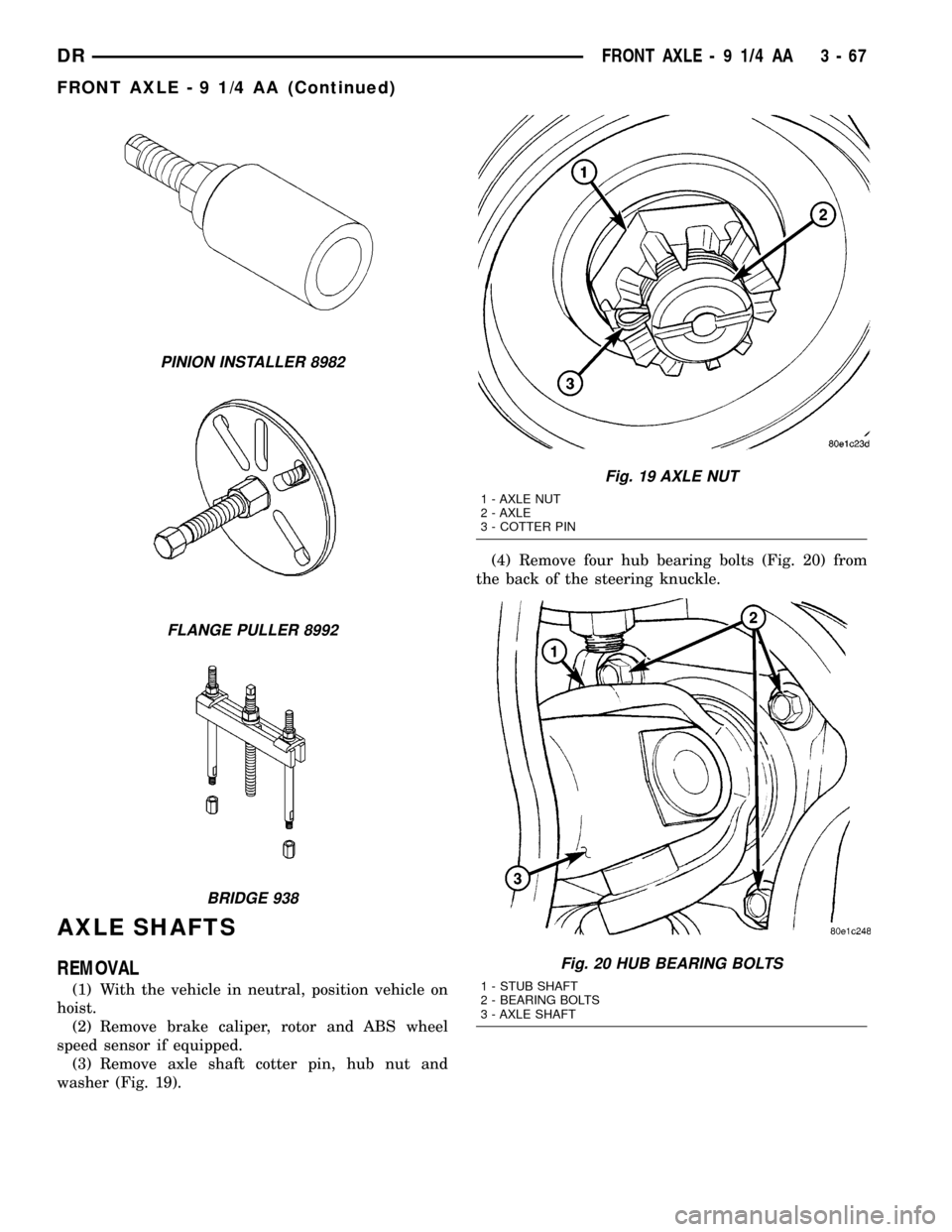
(3) Remove axle shaft cotter pin, hub nut and
washer (Fig. 19).(4) Remove four hub bearing bolts (Fig. 20) from
the back of the steering knuckle.
PINION INSTALLER 8982
FLANGE PULLER 8992
BRIDGE 938
Fig. 19 AXLE NUT
1 - AXLE NUT
2 - AXLE
3 - COTTER PIN
Fig. 20 HUB BEARING BOLTS
1 - STUB SHAFT
2 - BEARING BOLTS
3 - AXLE SHAFT
DRFRONT AXLE - 9 1/4 AA 3 - 67
FRONT AXLE - 9 1/4 AA (Continued)
Page 150 of 2627
ASSEMBLY
(1) Pack the bearing caps 1/3 full of wheel bearing
lubricant. Apply extreme pressure (EP), lithium-base
lubricant to aid in installation.
(2) Position the spider in the yoke. Insert the seals
and bearings. Tap the bearing caps into the yoke
bores far enough to hold the spider in position.
(3) Place the socket (driver) against one bearing
cap. Position the yoke with the socket in a vise.
(4) Tighten the vise to force the bearing caps into
the yoke. Force the caps enough to install the retain-
ing clips.
(5) Install the bearing cap retaining clips.
(6) Install axle shaft.
INSTALLATION
(1) Clean axle shaft and apply a thin film of
Mopar Wheel Bearing Grease to the shaft splines
and hub bore.
(2) Install axle shaft through the steering knuckle
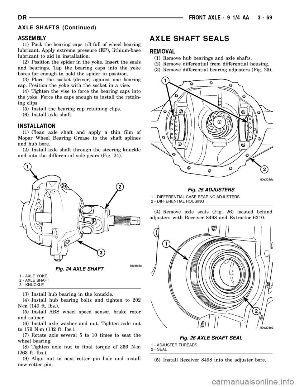
and into the differential side gears (Fig. 24).
(3) Install hub bearing in the knuckle.
(4) Install hub bearing bolts and tighten to 202
N´m (149 ft. lbs.).
(5) Install ABS wheel speed sensor, brake rotor
and caliper.
(6) Install axle washer and nut. Tighten axle nut
to 179 N´m (132 ft. lbs.).
(7) Rotate axle several 5 to 10 times to seat the
wheel bearing.
(8) Tighten axle nut to final torque of 356 N´m
(263 ft. lbs.).
(9) Align nut to next cotter pin hole and install
new cotter pin.
AXLE SHAFT SEALS
REMOVAL
(1) Remove hub bearings and axle shafts.
(2) Remove differential from differential housing.
(3) Remove differential bearing adjusters (Fig. 25).
(4) Remove axle seals (Fig. 26) located behind
adjusters with Receiver 8498 and Extractor 6310.
(5) Install Receiver 8498 into the adjuster bore.
Fig. 24 AXLE SHAFT
1 - AXLE YOKE
2 - AXLE SHAFT
3 - KNUCKLE
Fig. 25 ADJUSTERS
1 - DIFFERENTIAL CASE BEARING ADJUSTERS
2 - DIFFERENTIAL HOUSING
Fig. 26 AXLE SHAFT SEAL
1 - ADJUSTER THREADS
2 - SEAL
DRFRONT AXLE - 9 1/4 AA 3 - 69
AXLE SHAFTS (Continued)
Page 178 of 2627
(10) If rotating torque is low, use Holder 6719 to
hold the companion flange and tighten pinion nut in
6.8 N´m (5 ft. lbs.) increments until proper rotating
torque is achieved.
NOTE: The bearing rotating torque should be con-
stant during a complete revolution of the pinion. If
the rotating torque varies, this indicates a binding
condition.
NOTE: The seal replacement is unacceptable if the
final pinion nut torque is less than 285 N´m (210 ft.
lbs.).
(11) Install propeller shaft with the installation
reference marks aligned.
(12) Tighten the companion flange bolts to 108
N´m (80 ft. lbs.).
(13) Install brake rotors.
(14) Check the differential lubricant level.
DIFFERENTIAL COVER
REMOVAL
(1) With vehicle in neutral, position vehicle on
hoist.
(2) Remove drain plug.
(3) Remove cover bolts.
(4) Remove cover and drain lubricant.
INSTALLATION
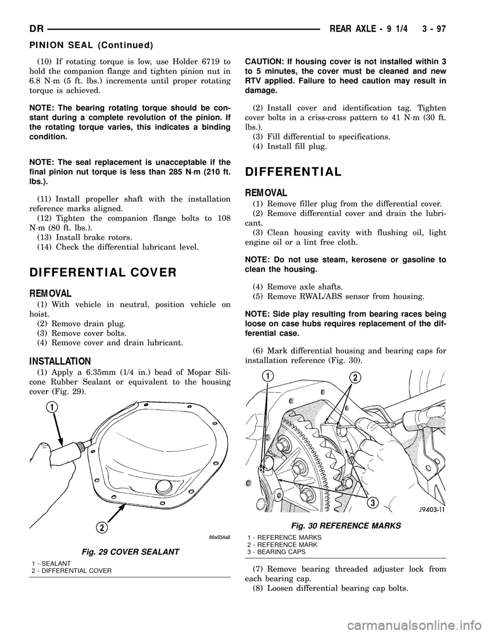
(1) Apply a 6.35mm (1/4 in.) bead of Mopar Sili-
cone Rubber Sealant or equivalent to the housing
cover (Fig. 29).CAUTION: If housing cover is not installed within 3
to 5 minutes, the cover must be cleaned and new
RTV applied. Failure to heed caution may result in
damage.
(2) Install cover and identification tag. Tighten
cover bolts in a criss-cross pattern to 41 N´m (30 ft.
lbs.).
(3) Fill differential to specifications.
(4) Install fill plug.
DIFFERENTIAL
REMOVAL
(1) Remove filler plug from the differential cover.
(2) Remove differential cover and drain the lubri-
cant.
(3) Clean housing cavity with flushing oil, light
engine oil or a lint free cloth.
NOTE: Do not use steam, kerosene or gasoline to
clean the housing.
(4) Remove axle shafts.
(5) Remove RWAL/ABS sensor from housing.
NOTE: Side play resulting from bearing races being
loose on case hubs requires replacement of the dif-
ferential case.
(6) Mark differential housing and bearing caps for
installation reference (Fig. 30).
(7) Remove bearing threaded adjuster lock from
each bearing cap.
(8) Loosen differential bearing cap bolts.
Fig. 29 COVER SEALANT
1 - SEALANT
2 - DIFFERENTIAL COVER
Fig. 30 REFERENCE MARKS
1 - REFERENCE MARKS
2 - REFERENCE MARK
3 - BEARING CAPS
DRREAR AXLE - 9 1/4 3 - 97
PINION SEAL (Continued)
Page 261 of 2627
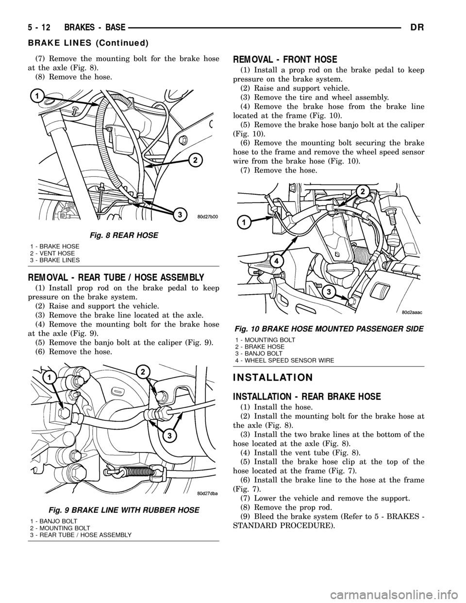
(7) Remove the mounting bolt for the brake hose
at the axle (Fig. 8).
(8) Remove the hose.
REMOVAL - REAR TUBE / HOSE ASSEMBLY
(1) Install prop rod on the brake pedal to keep
pressure on the brake system.
(2) Raise and support the vehicle.
(3) Remove the brake line located at the axle.
(4) Remove the mounting bolt for the brake hose
at the axle (Fig. 9).
(5) Remove the banjo bolt at the caliper (Fig. 9).
(6) Remove the hose.
REMOVAL - FRONT HOSE
(1) Install a prop rod on the brake pedal to keep
pressure on the brake system.
(2) Raise and support vehicle.
(3) Remove the tire and wheel assembly.
(4) Remove the brake hose from the brake line
located at the frame (Fig. 10).
(5) Remove the brake hose banjo bolt at the caliper
(Fig. 10).
(6) Remove the mounting bolt securing the brake
hose to the frame and remove the wheel speed sensor
wire from the brake hose (Fig. 10).
(7) Remove the hose.
INSTALLATION
INSTALLATION - REAR BRAKE HOSE
(1) Install the hose.
(2) Install the mounting bolt for the brake hose at
the axle (Fig. 8).
(3) Install the two brake lines at the bottom of the
hose located at the axle (Fig. 8).
(4) Install the vent tube (Fig. 8).
(5) Install the brake hose clip at the top of the
hose located at the frame (Fig. 7).
(6) Install the brake line to the hose at the frame
(Fig. 7).
(7) Lower the vehicle and remove the support.
(8) Remove the prop rod.
(9) Bleed the brake system (Refer to 5 - BRAKES -
STANDARD PROCEDURE).
Fig. 8 REAR HOSE
1 - BRAKE HOSE
2 - VENT HOSE
3 - BRAKE LINES
Fig. 9 BRAKE LINE WITH RUBBER HOSE
1 - BANJO BOLT
2 - MOUNTING BOLT
3 - REAR TUBE / HOSE ASSEMBLY
Fig. 10 BRAKE HOSE MOUNTED PASSENGER SIDE
1 - MOUNTING BOLT
2 - BRAKE HOSE
3 - BANJO BOLT
4 - WHEEL SPEED SENSOR WIRE
5 - 12 BRAKES - BASEDR
BRAKE LINES (Continued)