transmission oil DODGE RAM 1500 1998 2.G User Guide
[x] Cancel search | Manufacturer: DODGE, Model Year: 1998, Model line: RAM 1500, Model: DODGE RAM 1500 1998 2.GPages: 2627
Page 33 of 2627
CAUTION: Do not crank starter motor on disabled
vehicle for more than 15 seconds, starter will over-
heat and could fail.
(7) Allow battery in disabled vehicle to charge to
at least 12.4 volts (75% charge) before attempting to
start engine. If engine does not start within 15 sec-
onds, stop cranking engine and allow starter to cool
(15 min.), before cranking again.
DISCONNECT CABLE CLAMPS AS FOLLOWS:
²Disconnect BLACK cable clamp from engine
ground on disabled vehicle.
²When using a Booster vehicle, disconnect
BLACK cable clamp from battery negative terminal.
Disconnect RED cable clamp from battery positive
terminal.
²Disconnect RED cable clamp from battery posi-
tive terminal on disabled vehicle.
HOISTING
STANDARD PROCEDURE - HOISTING
Refer to the Owner's Manual for emergency vehicle
lifting procedures.
WARNING: THE HOISTING AND JACK LIFTING
POINTS PROVIDED ARE FOR A COMPLETE VEHI-
CLE. WHEN A CHASSIS OR DRIVETRAIN COMPO-
NENT IS REMOVED FROM A VEHICLE, THE
CENTER OF GRAVITY IS ALTERED MAKING SOME
HOISTING CONDITIONS UNSTABLE. PROPERLY
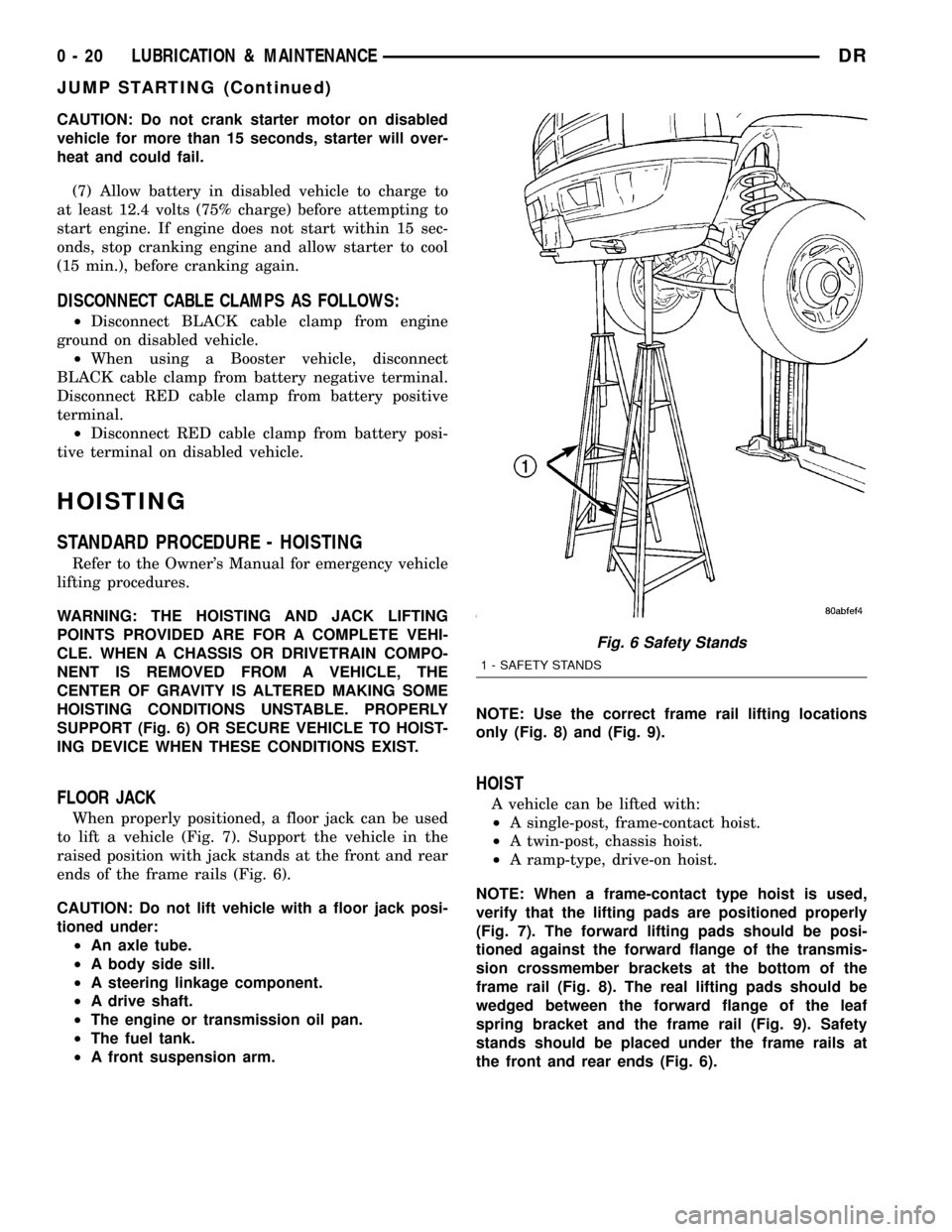
SUPPORT (Fig. 6) OR SECURE VEHICLE TO HOIST-
ING DEVICE WHEN THESE CONDITIONS EXIST.
FLOOR JACK
When properly positioned, a floor jack can be used
to lift a vehicle (Fig. 7). Support the vehicle in the
raised position with jack stands at the front and rear
ends of the frame rails (Fig. 6).
CAUTION: Do not lift vehicle with a floor jack posi-
tioned under:
²An axle tube.
²A body side sill.
²A steering linkage component.
²A drive shaft.
²The engine or transmission oil pan.
²The fuel tank.
²A front suspension arm.NOTE: Use the correct frame rail lifting locations
only (Fig. 8) and (Fig. 9).
HOIST
A vehicle can be lifted with:
²A single-post, frame-contact hoist.
²A twin-post, chassis hoist.
²A ramp-type, drive-on hoist.
NOTE: When a frame-contact type hoist is used,
verify that the lifting pads are positioned properly
(Fig. 7). The forward lifting pads should be posi-
tioned against the forward flange of the transmis-
sion crossmember brackets at the bottom of the
frame rail (Fig. 8). The real lifting pads should be
wedged between the forward flange of the leaf
spring bracket and the frame rail (Fig. 9). Safety
stands should be placed under the frame rails at
the front and rear ends (Fig. 6).
Fig. 6 Safety Stands
1 - SAFETY STANDS
0 - 20 LUBRICATION & MAINTENANCEDR
JUMP STARTING (Continued)
Page 35 of 2627
A wooden crossbeam may be required for proper
connection when using the sling-type, front-end tow-
ing method.
SAFETY PRECAUTIONS
CAUTION: The following safety precautions must be
observed when towing a vehicle:
²Secure loose and protruding parts.
²Always use a safety chain system that is inde-
pendent of the lifting and towing equipment.
²Do not allow towing equipment to contact the
disabled vehicle's fuel tank.
²Do not allow anyone under the disabled vehicle
while it is lifted by the towing device.
²Do not allow passengers to ride in a vehicle
being towed.
²Always observe state and local laws regarding
towing regulations.
²Do not tow a vehicle in a manner that could
jeopardize the safety of the operator, pedestrians or
other motorists.
²Do not attach tow chains, T-hooks, J-hooks, or a
tow sling to a bumper, steering linkage, drive shafts
or a non-reinforced frame hole.
²Do not tow a heavily loaded vehicle. Damage to
the cab, cargo box or frame may result. Use a flatbed
device to transport a loaded vehicle.
GROUND CLEARANCE
CAUTION: If vehicle is towed with wheels removed,
install lug nuts to retain brake drums or rotors.
A towed vehicle should be raised until lifted wheels
are a minimum 100 mm (4 in) from the ground. Be
sure there is adequate ground clearance at the oppo-
site end of the vehicle, especially when towing over
rough terrain or steep rises in the road. If necessary,remove the wheels from the lifted end of the vehicle
and lower the vehicle closer to the ground, to
increase the ground clearance at the opposite end of
the vehicle. Install lug nuts on wheel attaching studs
to retain brake drums or rotors.
RAMP ANGLE
If a vehicle with flat-bed towing equipment is used,
the approach ramp angle should not exceed 15
degrees.
TOWING WHEN KEYS ARE NOT AVAILABLE
When the vehicle is locked and keys are not avail-
able, use a flat bed hauler. A Wheel-lift or Sling-type
device can be used on 4WD vehicles providedall the
wheels are lifted off the ground using tow dol-
lies.
FOUR-WHEEL-DRIVE VEHICLE TOWING
Chrysler Corporation recommends that a vehicle be
transported on a flat-bed device. A Wheel-lift or
Sling-type device can be used providedall the
wheels are lifted off the ground using tow dol-
lies.
WARNING: WHEN TOWING A DISABLED VEHICLE
AND THE DRIVE WHEELS ARE SECURED IN A
WHEEL LIFT OR TOW DOLLIES, ENSURE THE
TRANSMISSION IS IN THE PARK POSITION (AUTO-
MATIC TRANSMISSION) OR A FORWARD DRIVE
GEAR (MANUAL TRANSMISSION).
CAUTION: Many vehicles are equipped with air
dams, spoilers, and/or ground effect panels. To
avoid component damage, a wheel-lift towing vehi-
cle or a flat-bed hauling vehicle is recommended.
0 - 22 LUBRICATION & MAINTENANCEDR
TOWING (Continued)
Page 72 of 2627
KNUCKLE
REMOVAL
(1) Remove the hub bearing (Refer to 2 - SUSPEN-
SION/FRONT/HUB / BEARING - REMOVAL).
(2) Remove tie-rod or drag link end from the steer-
ing knuckle arm.
(3) Remove the ABS sensor wire and bracket from
knuckle. Refer to Brakes, for proper procedures.
(4) Remove the cotter pin from the upper ball stud
nut. Remove the upper and lower ball stud nuts.
(5) Strike the steering knuckle with a brass ham-
mer to loosen.
(6) Remove knuckle from axle tube yokes.
INSTALLATION
(1) Position the steering knuckle on the ball studs.
(2) Install and tighten lower ball stud nut to 47
N´m (35 ft. lbs.) torque. Do not install cotter pin at
this time.
(3) Install and tighten upper ball stud nut to 94
N´m (70 ft. lbs.) torque. Advance nut to next slot to
line up hole and install new cotter pin.
(4) Retorque lower ball stud nut to 190±217 N´m
(140±160 ft. lbs.) torque. Advance nut to next slot to
line up hole and install new cotter pin.
(5) Install the hub bearing (Refer to 2 - SUSPEN-
SION/FRONT/HUB / BEARING - INSTALLATION).
(6) Install tie-rod or drag link end onto the steer-
ing knuckle arm.
(7) Install the ABS sensor wire and bracket to the
knuckle. Refer to Brakes, for proper procedure.
UPPER SUSPENSION ARM
REMOVAL
REMOVAL - LEFT
(1) Raise and support the vehicle.
(2) Remove the upper suspension arm nut and bolt
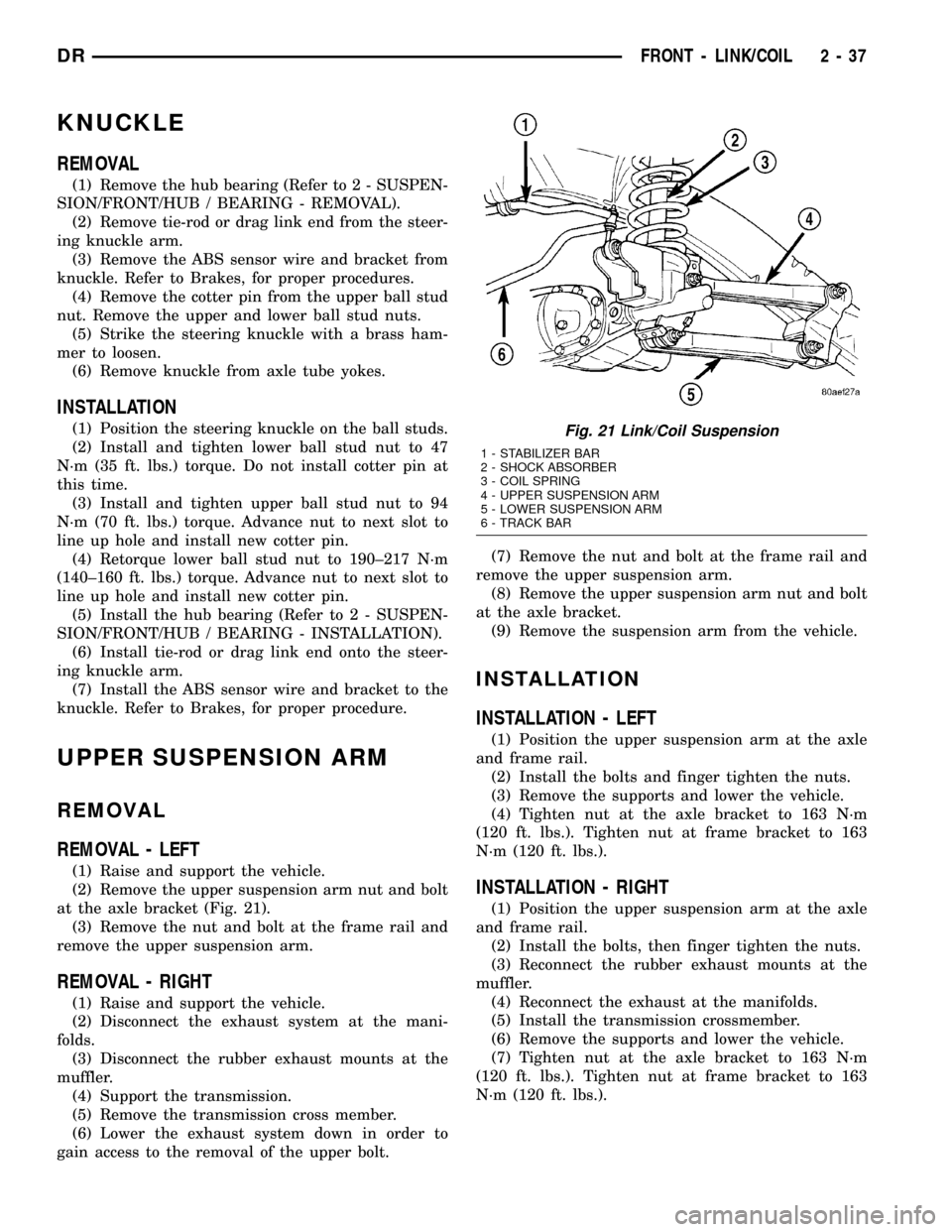
at the axle bracket (Fig. 21).
(3) Remove the nut and bolt at the frame rail and
remove the upper suspension arm.
REMOVAL - RIGHT
(1) Raise and support the vehicle.
(2) Disconnect the exhaust system at the mani-
folds.
(3) Disconnect the rubber exhaust mounts at the
muffler.
(4) Support the transmission.
(5) Remove the transmission cross member.
(6) Lower the exhaust system down in order to
gain access to the removal of the upper bolt.(7) Remove the nut and bolt at the frame rail and
remove the upper suspension arm.
(8) Remove the upper suspension arm nut and bolt
at the axle bracket.
(9) Remove the suspension arm from the vehicle.
INSTALLATION
INSTALLATION - LEFT
(1) Position the upper suspension arm at the axle
and frame rail.
(2) Install the bolts and finger tighten the nuts.
(3) Remove the supports and lower the vehicle.
(4) Tighten nut at the axle bracket to 163 N´m
(120 ft. lbs.). Tighten nut at frame bracket to 163
N´m (120 ft. lbs.).
INSTALLATION - RIGHT
(1) Position the upper suspension arm at the axle
and frame rail.
(2) Install the bolts, then finger tighten the nuts.
(3) Reconnect the rubber exhaust mounts at the
muffler.
(4) Reconnect the exhaust at the manifolds.
(5) Install the transmission crossmember.
(6) Remove the supports and lower the vehicle.
(7) Tighten nut at the axle bracket to 163 N´m
(120 ft. lbs.). Tighten nut at frame bracket to 163
N´m (120 ft. lbs.).
Fig. 21 Link/Coil Suspension
1 - STABILIZER BAR
2 - SHOCK ABSORBER
3 - COIL SPRING
4 - UPPER SUSPENSION ARM
5 - LOWER SUSPENSION ARM
6 - TRACK BAR
DRFRONT - LINK/COIL 2 - 37
Page 272 of 2627
(3) Install parking brake cable in the brake lever.
(4) Install the park brake shoes (Refer to 5 -
BRAKES/PARKING BRAKE/SHOES - INSTALLA-
TION). (Fig. 66).
(5) Install axle shaft, (Refer to 3 - DIFFEREN-
TIAL & DRIVELINE/REAR AXLE - 9 1/4/AXLE
SHAFTS - INSTALLATION).
(6) Adjust brake shoes to drum with brake gauge
(Refer to 5 - BRAKES/PARKING BRAKE/SHOES -
ADJUSTMENTS).
(7) Install the rotor (Refer to 5 - BRAKES/HY-
DRAULIC/MECHANICAL/ROTORS - INSTALLA-
TION).
(8) Install the caliper adapter (Refer to 5 -
BRAKES/HYDRAULIC/MECHANICAL/DISC
BRAKE CALIPER ADAPTER - INSTALLATION).
(9) Install the caliper (Refer to 5 - BRAKES/HY-
DRAULIC/MECHANICAL/DISC BRAKE CALIPERS
- INSTALLATION).
(10) Install wheel and tire assembly.
FLUID
DIAGNOSIS AND TESTING - BRAKE FLUID
CONTAMINATION
Indications of fluid contamination are swollen or
deteriorated rubber parts.
Swollen rubber parts indicate the presence of
petroleum in the brake fluid.
To test for contamination, put a small amount of
drained brake fluid in clear glass jar. If fluid sepa-
rates into layers, there is mineral oil or other fluid
contamination of the brake fluid.
If brake fluid is contaminated, drain and thor-
oughly flush system. Replace master cylinder, propor-
tioning valve, caliper seals, wheel cylinder seals,
Antilock Brakes hydraulic unit and all hydraulic
fluid hoses.
STANDARD PROCEDURE - BRAKE FLUID
LEVEL
Always clean the master cylinder reservoir and
caps before checking fluid level. If not cleaned, dirt
could enter the fluid.
The fluid fill level is indicated on the side of the
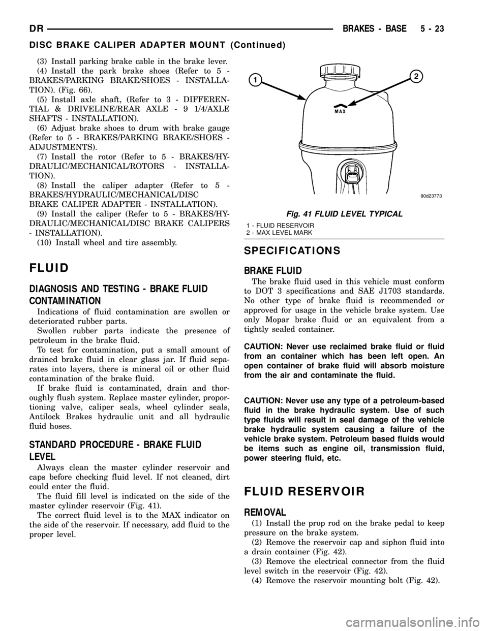
master cylinder reservoir (Fig. 41).
The correct fluid level is to the MAX indicator on
the side of the reservoir. If necessary, add fluid to the
proper level.
SPECIFICATIONS
BRAKE FLUID
The brake fluid used in this vehicle must conform
to DOT 3 specifications and SAE J1703 standards.
No other type of brake fluid is recommended or
approved for usage in the vehicle brake system. Use
only Mopar brake fluid or an equivalent from a
tightly sealed container.
CAUTION: Never use reclaimed brake fluid or fluid
from an container which has been left open. An
open container of brake fluid will absorb moisture
from the air and contaminate the fluid.
CAUTION: Never use any type of a petroleum-based
fluid in the brake hydraulic system. Use of such
type fluids will result in seal damage of the vehicle
brake hydraulic system causing a failure of the
vehicle brake system. Petroleum based fluids would
be items such as engine oil, transmission fluid,
power steering fluid, etc.
FLUID RESERVOIR
REMOVAL
(1) Install the prop rod on the brake pedal to keep
pressure on the brake system.
(2) Remove the reservoir cap and siphon fluid into
a drain container (Fig. 42).
(3) Remove the electrical connector from the fluid
level switch in the reservoir (Fig. 42).
(4) Remove the reservoir mounting bolt (Fig. 42).
Fig. 41 FLUID LEVEL TYPICAL
1 - FLUID RESERVOIR
2 - MAX LEVEL MARK
DRBRAKES - BASE 5 - 23
DISC BRAKE CALIPER ADAPTER MOUNT (Continued)
Page 302 of 2627
CLUTCH
TABLE OF CONTENTS
page page
CLUTCH
WARNING.............................1
DIAGNOSIS AND TESTING................1
SPECIFICATIONS........................5
CLUTCH DISC
REMOVAL.............................5
INSTALLATION..........................5
CLUTCH HOUSING
DIAGNOSIS AND TESTING................7
REMOVAL.............................9
INSTALLATION..........................9
CLUTCH RELEASE BEARING
REMOVAL.............................9
INSTALLATION.........................10
FLYWHEEL
DIAGNOSIS AND TESTING................10REMOVAL.............................11
DISASSEMBLY.........................11
ASSEMBLY............................11
INSTALLATION.........................11
PILOT BEARING
REMOVAL.............................11
INSTALLATION.........................12
LINKAGE
REMOVAL.............................12
INSTALLATION.........................12
CLUTCH PEDAL POSITION SWITCH
DESCRIPTION.........................13
OPERATION...........................13
DIAGNOSIS AND TESTING................13
CLUTCH
WARNING
WARNING: Exercise care when servicing clutch
components. Factory installed clutch discs do not
contain asbestos fibers. Dust and dirt on clutch
parts may contain asbestos fibers from aftermarket
components. Breathing excessive concentrations of
these fibers can cause serious bodily harm. Wear a
respirator during service and never clean clutch
components with compressed air or with a dry
brush. Either clean the components with water
dampened rags or use a vacuum cleaner specifi-
cally designed to remove asbestos fibers and dust.
Do not create dust by sanding a clutch discs.
Replace the disc if the friction material is damaged.
Dispose of all dust and dirt containing asbestos
fibers in sealed bags or containers. This will mini-
mize exposure to yourself and to others. Follow all
recommended safety practices prescribed by the
occupational safety and health administration
(OSHA) and the environmental safety agency (EPA),
for the handling and disposal of products contain-
ing asbestos. Failure to follow these instructions
may result in personal injury or death
DIAGNOSIS AND TESTING
Road test and inspect components to determine a
clutch problem. Road test the vehicle at normalspeeds. Shift the transmission through all gear
ranges and observe clutch action. If clutch chatters,
grabs, slips or does not release properly, remove and
inspect clutch components. If problem is noise or
hard shifting, further diagnosis may be needed to the
transmission and driveline component.
CLUTCH CONTAMINATION
Contamination is a frequent cause of clutch mal-
functions. Oil, water or clutch fluid on the clutch disc
and pressure plate surfaces will cause chatter, slip
and grab. Oil contamination indicates a leak at
either the rear main seal or transmission input shaft.
Clutch fluid leaks are usually from damaged slave
cylinder push rod seals. Heat buildup caused by slip-
page between the pressure plate, disc and flywheel
can bake the oil residue onto the components. The
glaze-like residue ranges in color from amber to
black.
Road splash contamination is dirt/water entering
the clutch housing due to loose bolts, housing cracks.
Driving through deep water puddles can force water/
road splash into the housing through such openings.
IMPROPER RELEASE OR CLUTCH ENGAGEMENT
Clutch release or engagement problems can be
caused by worn or damage clutch components.
Release problems can cause hard shifting and
noise. Look for leaks at clutch cylinders, connecting
line and loose slave cylinder bolts. Also worn/loose
release fork, pivot stud, clutch disc, pressure plate or
release bearing.
DRCLUTCH 6 - 1
Page 304 of 2627
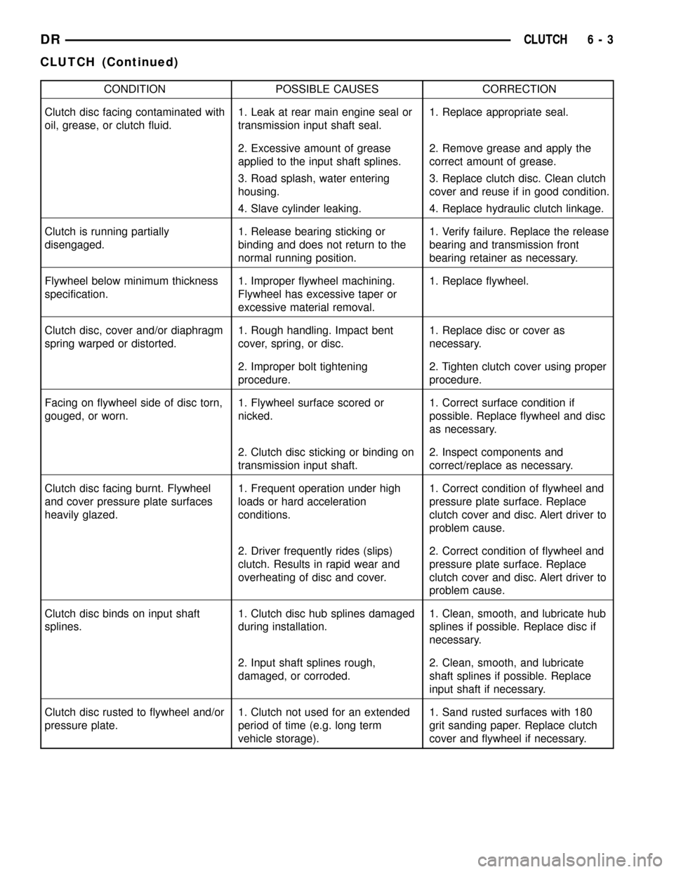
CONDITION POSSIBLE CAUSES CORRECTION
Clutch disc facing contaminated with
oil, grease, or clutch fluid.1. Leak at rear main engine seal or
transmission input shaft seal.1. Replace appropriate seal.
2. Excessive amount of grease
applied to the input shaft splines.2. Remove grease and apply the
correct amount of grease.
3. Road splash, water entering
housing.3. Replace clutch disc. Clean clutch
cover and reuse if in good condition.
4. Slave cylinder leaking. 4. Replace hydraulic clutch linkage.
Clutch is running partially
disengaged.1. Release bearing sticking or
binding and does not return to the
normal running position.1. Verify failure. Replace the release
bearing and transmission front
bearing retainer as necessary.
Flywheel below minimum thickness
specification.1. Improper flywheel machining.
Flywheel has excessive taper or
excessive material removal.1. Replace flywheel.
Clutch disc, cover and/or diaphragm
spring warped or distorted.1. Rough handling. Impact bent
cover, spring, or disc.1. Replace disc or cover as
necessary.
2. Improper bolt tightening
procedure.2. Tighten clutch cover using proper
procedure.
Facing on flywheel side of disc torn,
gouged, or worn.1. Flywheel surface scored or
nicked.1. Correct surface condition if
possible. Replace flywheel and disc
as necessary.
2. Clutch disc sticking or binding on
transmission input shaft.2. Inspect components and
correct/replace as necessary.
Clutch disc facing burnt. Flywheel
and cover pressure plate surfaces
heavily glazed.1. Frequent operation under high
loads or hard acceleration
conditions.1. Correct condition of flywheel and
pressure plate surface. Replace
clutch cover and disc. Alert driver to
problem cause.
2. Driver frequently rides (slips)
clutch. Results in rapid wear and
overheating of disc and cover.2. Correct condition of flywheel and
pressure plate surface. Replace
clutch cover and disc. Alert driver to
problem cause.
Clutch disc binds on input shaft
splines.1. Clutch disc hub splines damaged
during installation.1. Clean, smooth, and lubricate hub
splines if possible. Replace disc if
necessary.
2. Input shaft splines rough,
damaged, or corroded.2. Clean, smooth, and lubricate
shaft splines if possible. Replace
input shaft if necessary.
Clutch disc rusted to flywheel and/or
pressure plate.1. Clutch not used for an extended
period of time (e.g. long term
vehicle storage).1. Sand rusted surfaces with 180
grit sanding paper. Replace clutch
cover and flywheel if necessary.
DRCLUTCH 6 - 3
CLUTCH (Continued)
Page 318 of 2627
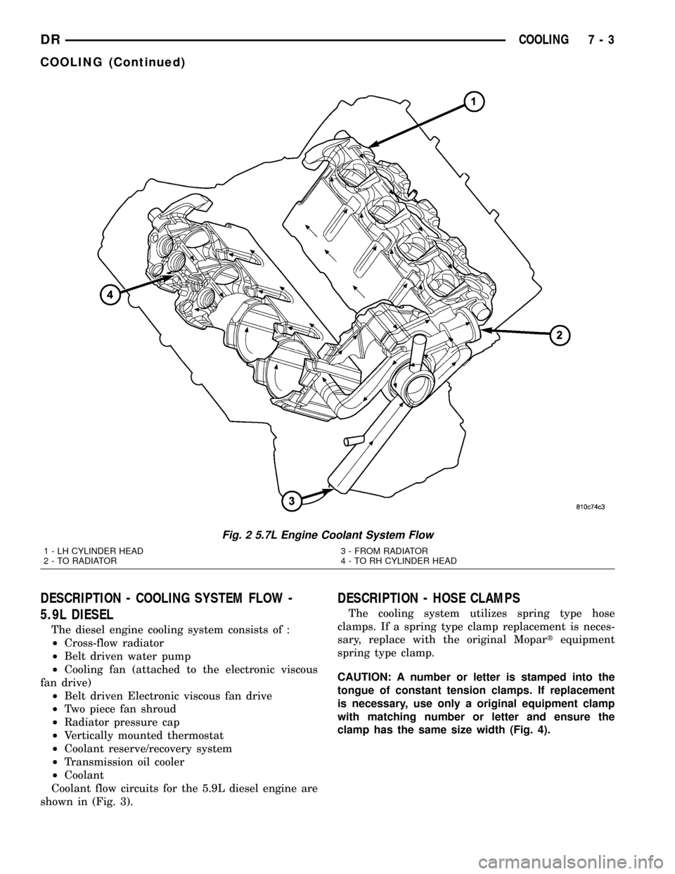
DESCRIPTION - COOLING SYSTEM FLOW -
5.9L DIESEL
The diesel engine cooling system consists of :
²Cross-flow radiator
²Belt driven water pump
²Cooling fan (attached to the electronic viscous
fan drive)
²Belt driven Electronic viscous fan drive
²Two piece fan shroud
²Radiator pressure cap
²Vertically mounted thermostat
²Coolant reserve/recovery system
²Transmission oil cooler
²Coolant
Coolant flow circuits for the 5.9L diesel engine are
shown in (Fig. 3).
DESCRIPTION - HOSE CLAMPS
The cooling system utilizes spring type hose
clamps. If a spring type clamp replacement is neces-
sary, replace with the original Mopartequipment
spring type clamp.
CAUTION: A number or letter is stamped into the
tongue of constant tension clamps. If replacement
is necessary, use only a original equipment clamp
with matching number or letter and ensure the
clamp has the same size width (Fig. 4).
Fig. 2 5.7L Engine Coolant System Flow
1 - LH CYLINDER HEAD
2 - TO RADIATOR3 - FROM RADIATOR
4 - TO RH CYLINDER HEAD
DRCOOLING 7 - 3
COOLING (Continued)
Page 321 of 2627
PRESSURE TESTER METHOD
The engine should be at normal operating temper-
ature. Recheck the system cold if the cause of coolant
loss is not located during the warm engine examina-
tion.
WARNING: HOT, PRESSURIZED COOLANT CAN
CAUSE INJURY BY SCALDING.
Carefully remove the radiator pressure cap from
the filler neck and check the coolant level. Push
down on the cap to disengage it from the stop tabs.
Wipe the inside of the filler neck and examine the
lower inside sealing seat for nicks, cracks, paint, dirt
and solder residue. Inspect the radiator-to- reserve/
overflow tank hose for internal obstructions. Insert a
wire through the hose to be sure it is not obstructed.
Inspect the cams on the outside of the filler neck.
If the cams are damaged, seating of the pressure cap
valve and tester seal will be affected.
Attach pressure tester (7700 or an equivalent) to
radiator filler neck.
Operate the tester pump to apply 103.4 kPa (15
psi) pressure to the system. If the hoses enlarge
excessively or bulges while testing, replace as neces-
sary. Observe the gauge pointer and determine the
condition of the cooling system according to following
criteria:
Holds Steady:If the pointer remains steady for
two minutes, serious coolant leaks are not present in
system. However, there could be an internal leakthat does not appear with normal system test pres-
sure. If it is certain that coolant is being lost and
leaks cannot be detected, inspect for interior leakage
or perform Internal Leakage Test. Refer to INTER-
NAL LEAKAGE INSPECTION.
Drops Slowly:Indicates a small leak or seepage
is occurring. Examine all of the connections for seep-
age or slight leakage with a flashlight. Inspect the
radiator, hoses, gasket edges and heater. Seal the
small leak holes with a Sealer Lubricant (or equiva-
lent). Repair the leak holes and inspect the system
again with pressure applied.
Drops Quickly:Indicates that serious leakage is
occurring. Examine the system for external leakage.
If leaks are not visible, inspect for internal leakage.
Large radiator leak holes should be repaired by a
reputable radiator repair shop.
INTERNAL LEAKAGE INSPECTION
Remove the engine oil pan drain plug and drain a
small amount of engine oil. If coolant is present in
the pan, it will drain first because it is heavier than
oil. An alternative method is to operate engine for a
short period to churn the oil. After this is done,
remove the engine dipstick and inspect for water
globules. Also inspect the transmission dipstick for
water globules and transmission fluid cooler for leak-
age.
WARNING: WITH RADIATOR PRESSURE TESTER
TOOL INSTALLED ON RADIATOR, DO NOT ALLOW
PRESSURE TO EXCEED 145 kPa (21 PSI). PRES-
SURE WILL BUILD UP QUICKLY IF A COMBUSTION
LEAK IS PRESENT. TO RELEASE PRESSURE,
ROCK TESTER FROM SIDE TO SIDE. WHEN
REMOVING TESTER, DO NOT TURN TESTER MORE
THAN 1/2 TURN IF SYSTEM IS UNDER PRESSURE.
Operate the engine without the pressure cap on
the radiator until the thermostat opens. Attach a
Pressure Tester to the filler neck. If pressure builds
up quickly it indicates a combustion leak exists. This
is usually the result of a cylinder head gasket leak or
crack in engine. Repair as necessary.
If there is not an immediate pressure increase,
pump the Pressure Tester. Do this until indicated
pressure is within system range of 110 kPa (16 psi).
Fluctuation of the gauge pointer indicates compres-
sion or combustion leakage into cooling system.
Because the vehicle is equipped with a catalytic
converter,do notshort out cylinders to isolate com-
pression leak.
If the needle on dial of the pressure tester does not
fluctuate, race engine a few times to check for an
abnormal amount of coolant or steam. This would be
emitting from exhaust pipe. Coolant or steam from
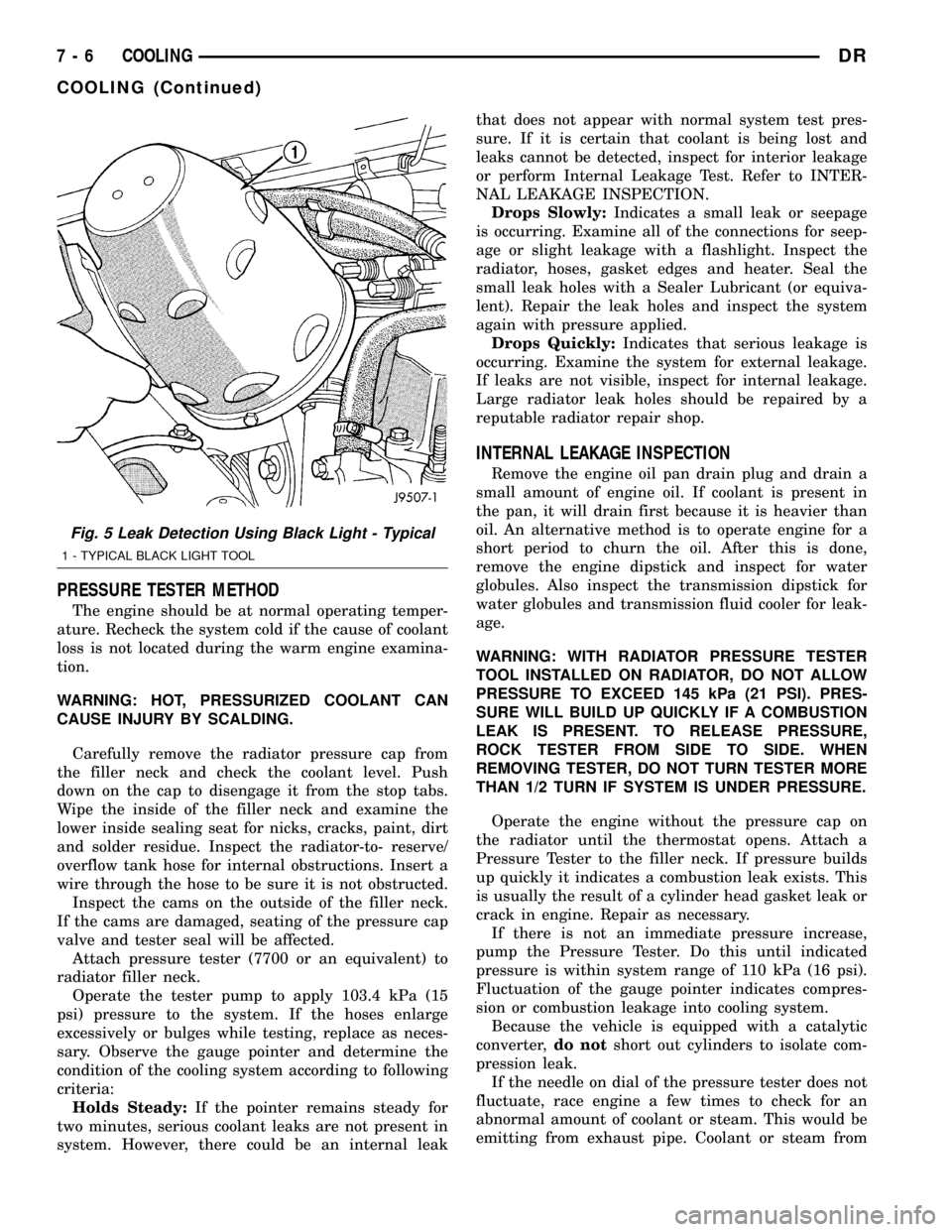
Fig. 5 Leak Detection Using Black Light - Typical
1 - TYPICAL BLACK LIGHT TOOL
7 - 6 COOLINGDR
COOLING (Continued)
Page 334 of 2627
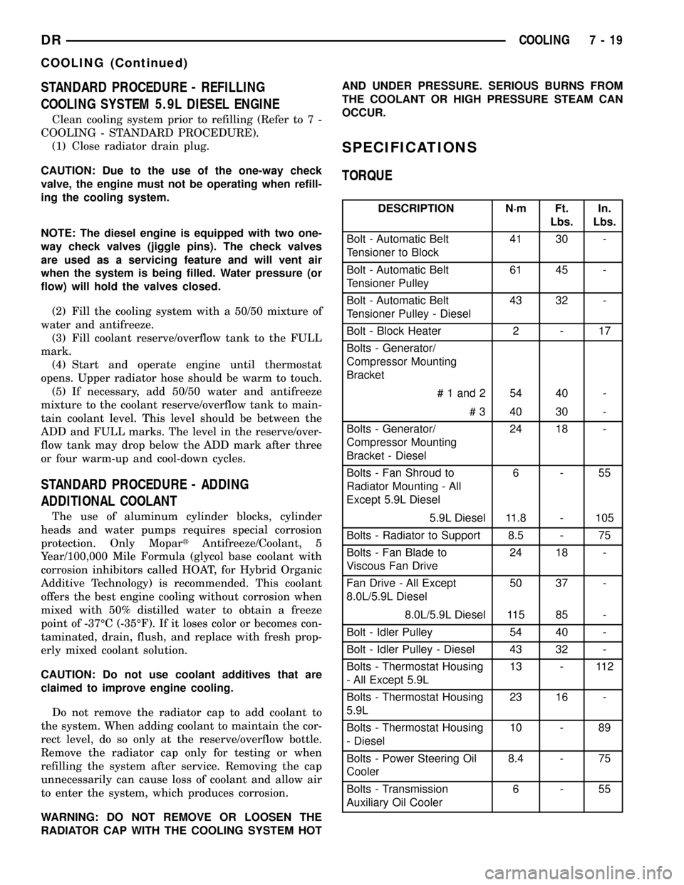
STANDARD PROCEDURE - REFILLING
COOLING SYSTEM 5.9L DIESEL ENGINE
Clean cooling system prior to refilling (Refer to 7 -
COOLING - STANDARD PROCEDURE).
(1) Close radiator drain plug.
CAUTION: Due to the use of the one-way check
valve, the engine must not be operating when refill-
ing the cooling system.
NOTE: The diesel engine is equipped with two one-
way check valves (jiggle pins). The check valves
are used as a servicing feature and will vent air
when the system is being filled. Water pressure (or
flow) will hold the valves closed.
(2) Fill the cooling system with a 50/50 mixture of
water and antifreeze.
(3) Fill coolant reserve/overflow tank to the FULL
mark.
(4) Start and operate engine until thermostat
opens. Upper radiator hose should be warm to touch.
(5) If necessary, add 50/50 water and antifreeze
mixture to the coolant reserve/overflow tank to main-
tain coolant level. This level should be between the
ADD and FULL marks. The level in the reserve/over-
flow tank may drop below the ADD mark after three
or four warm-up and cool-down cycles.
STANDARD PROCEDURE - ADDING
ADDITIONAL COOLANT
The use of aluminum cylinder blocks, cylinder
heads and water pumps requires special corrosion
protection. Only MopartAntifreeze/Coolant, 5
Year/100,000 Mile Formula (glycol base coolant with
corrosion inhibitors called HOAT, for Hybrid Organic
Additive Technology) is recommended. This coolant
offers the best engine cooling without corrosion when
mixed with 50% distilled water to obtain a freeze
point of -37ÉC (-35ÉF). If it loses color or becomes con-
taminated, drain, flush, and replace with fresh prop-
erly mixed coolant solution.
CAUTION: Do not use coolant additives that are
claimed to improve engine cooling.
Do not remove the radiator cap to add coolant to
the system. When adding coolant to maintain the cor-
rect level, do so only at the reserve/overflow bottle.
Remove the radiator cap only for testing or when
refilling the system after service. Removing the cap
unnecessarily can cause loss of coolant and allow air
to enter the system, which produces corrosion.
WARNING: DO NOT REMOVE OR LOOSEN THE
RADIATOR CAP WITH THE COOLING SYSTEM HOTAND UNDER PRESSURE. SERIOUS BURNS FROM
THE COOLANT OR HIGH PRESSURE STEAM CAN
OCCUR.
SPECIFICATIONS
TORQUE
DESCRIPTION N´m Ft.
Lbs.In.
Lbs.
Bolt - Automatic Belt
Tensioner to Block41 30 -
Bolt - Automatic Belt
Tensioner Pulley61 45 -
Bolt - Automatic Belt
Tensioner Pulley - Diesel43 32 -
Bolt - Block Heater 2 - 17
Bolts - Generator/
Compressor Mounting
Bracket
# 1 and 2 54 40 -
# 3 40 30 -
Bolts - Generator/
Compressor Mounting
Bracket - Diesel24 18 -
Bolts - Fan Shroud to
Radiator Mounting - All
Except 5.9L Diesel6-55
5.9L Diesel 11.8 - 105
Bolts - Radiator to Support 8.5 - 75
Bolts - Fan Blade to
Viscous Fan Drive24 18 -
Fan Drive - All Except
8.0L/5.9L Diesel50 37 -
8.0L/5.9L Diesel 115 85 -
Bolt - Idler Pulley 54 40 -
Bolt - Idler Pulley - Diesel 43 32 -
Bolts - Thermostat Housing
- All Except 5.9L13 - 112
Bolts - Thermostat Housing
5.9L23 16 -
Bolts - Thermostat Housing
- Diesel10 - 89
Bolts - Power Steering Oil
Cooler8.4 - 75
Bolts - Transmission
Auxiliary Oil Cooler6-55
DRCOOLING 7 - 19
COOLING (Continued)
Page 335 of 2627
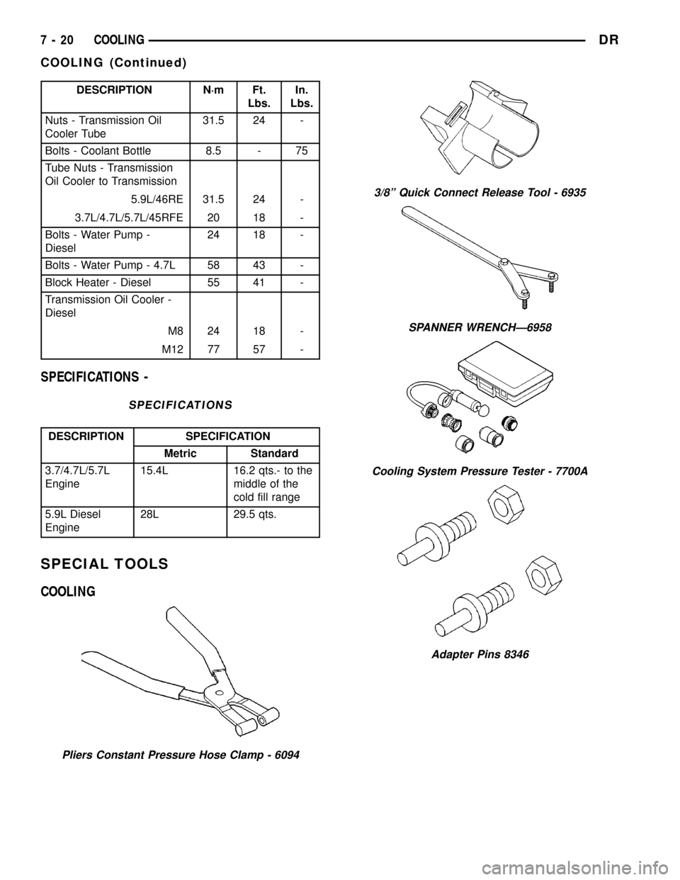
DESCRIPTION N´m Ft.
Lbs.In.
Lbs.
Nuts - Transmission Oil
Cooler Tube31.5 24 -
Bolts - Coolant Bottle 8.5 - 75
Tube Nuts - Transmission
Oil Cooler to Transmission
5.9L/46RE 31.5 24 -
3.7L/4.7L/5.7L/45RFE 20 18 -
Bolts - Water Pump -
Diesel24 18 -
Bolts - Water Pump - 4.7L 58 43 -
Block Heater - Diesel 55 41 -
Transmission Oil Cooler -
Diesel
M8 24 18 -
M12 77 57 -
SPECIFICATIONS -
SPECIFICATIONS
DESCRIPTION SPECIFICATION
Metric Standard
3.7/4.7L/5.7L
Engine15.4L 16.2 qts.- to the
middle of the
cold fill range
5.9L Diesel
Engine28L 29.5 qts.
SPECIAL TOOLS
COOLING
Pliers Constant Pressure Hose Clamp - 6094
3/8º Quick Connect Release Tool - 6935
SPANNER WRENCHÐ6958
Cooling System Pressure Tester - 7700A
Adapter Pins 8346
7 - 20 COOLINGDR
COOLING (Continued)